
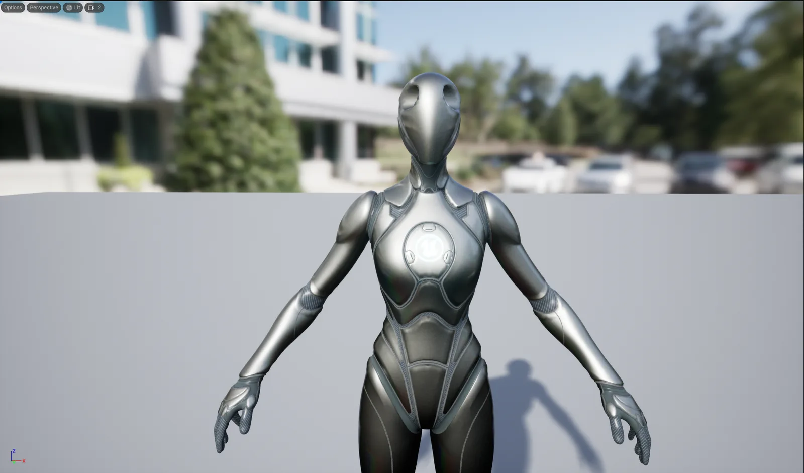
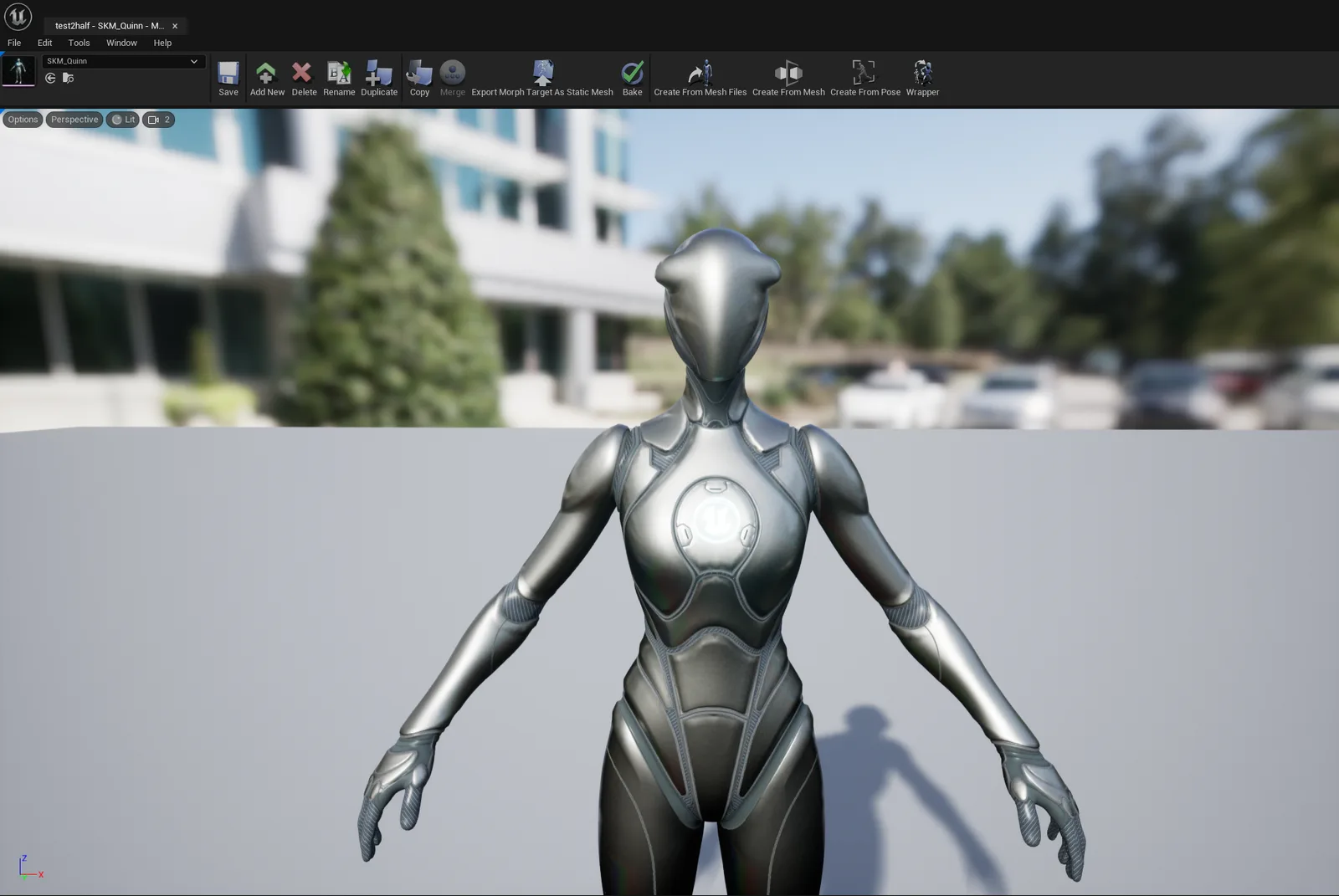
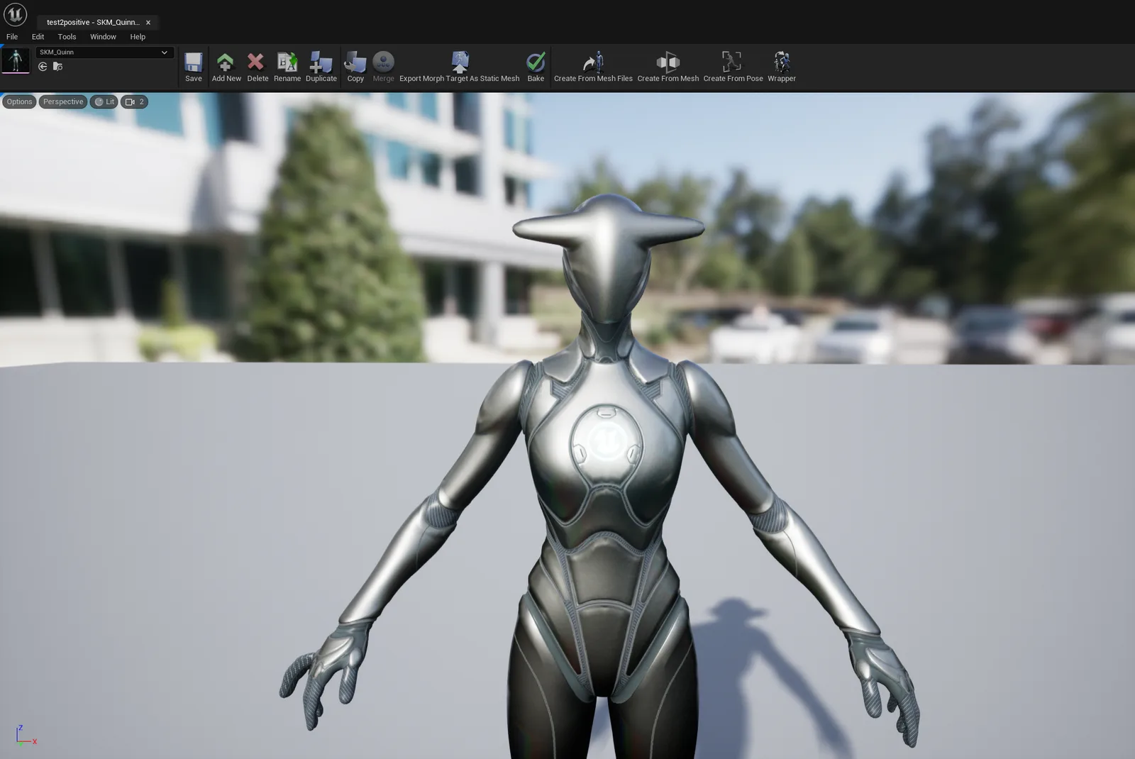
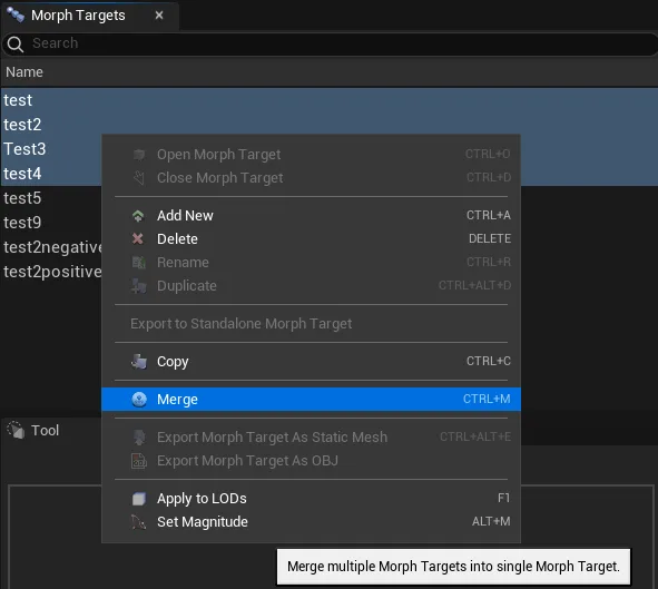
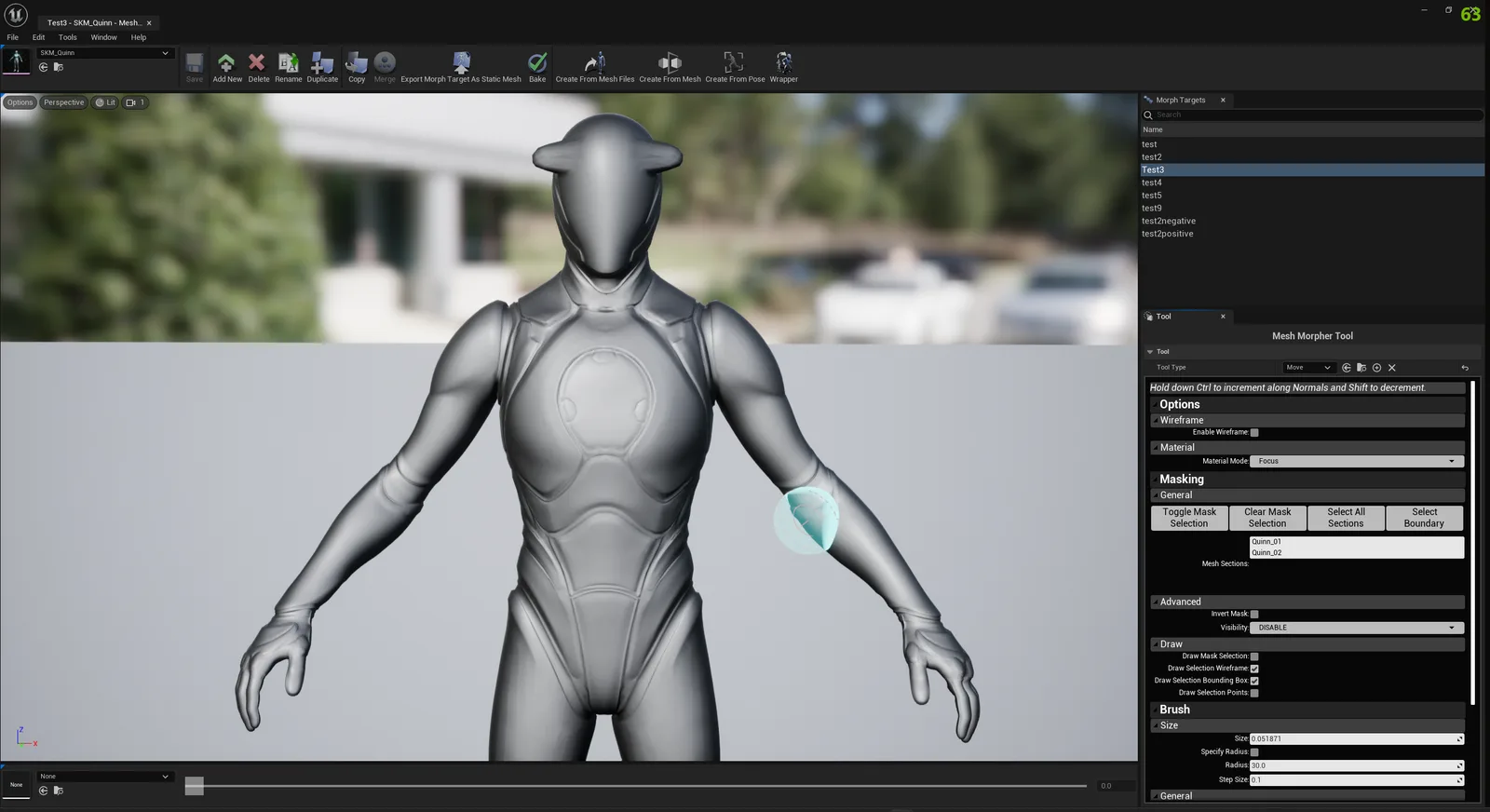
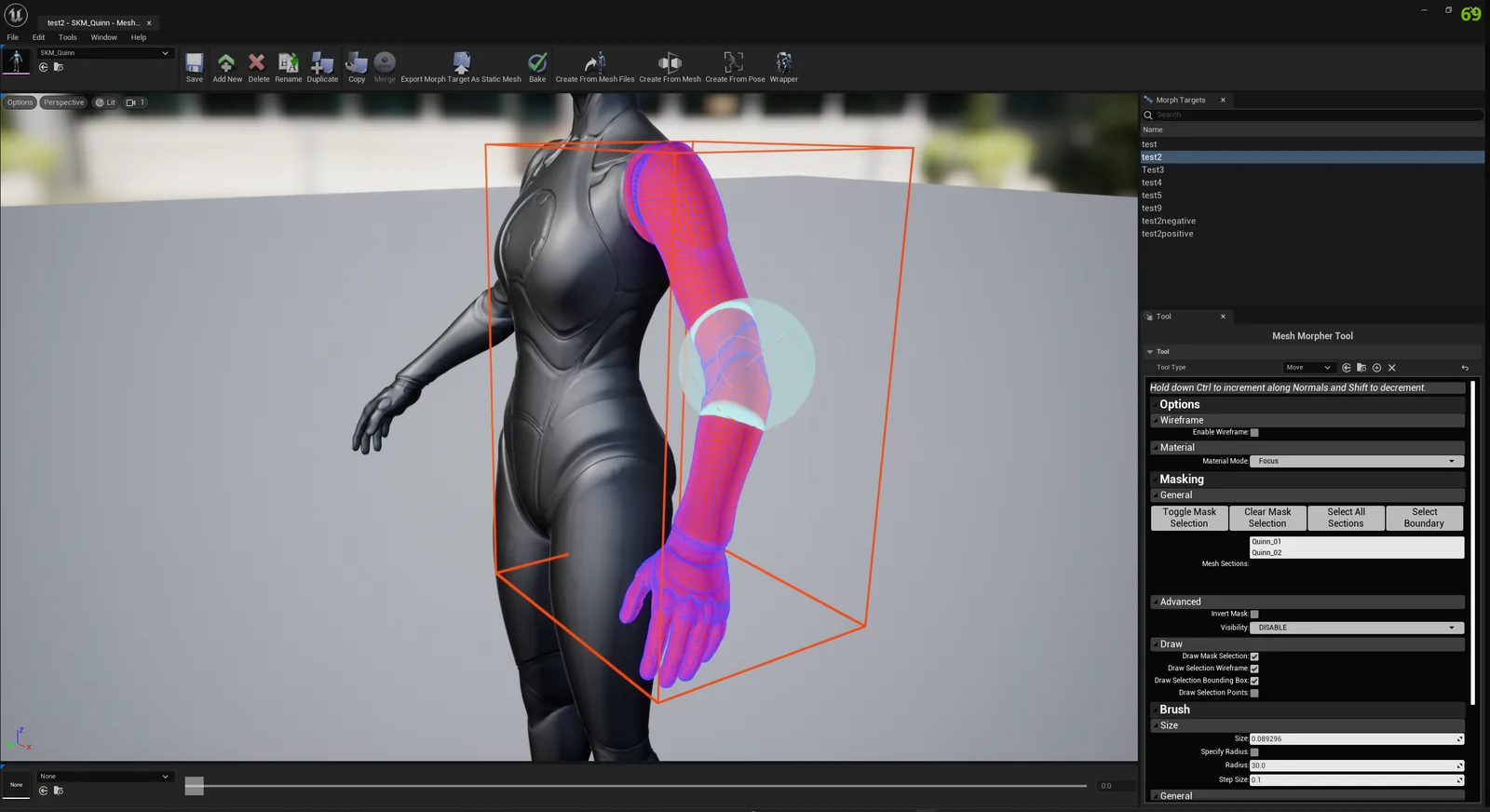
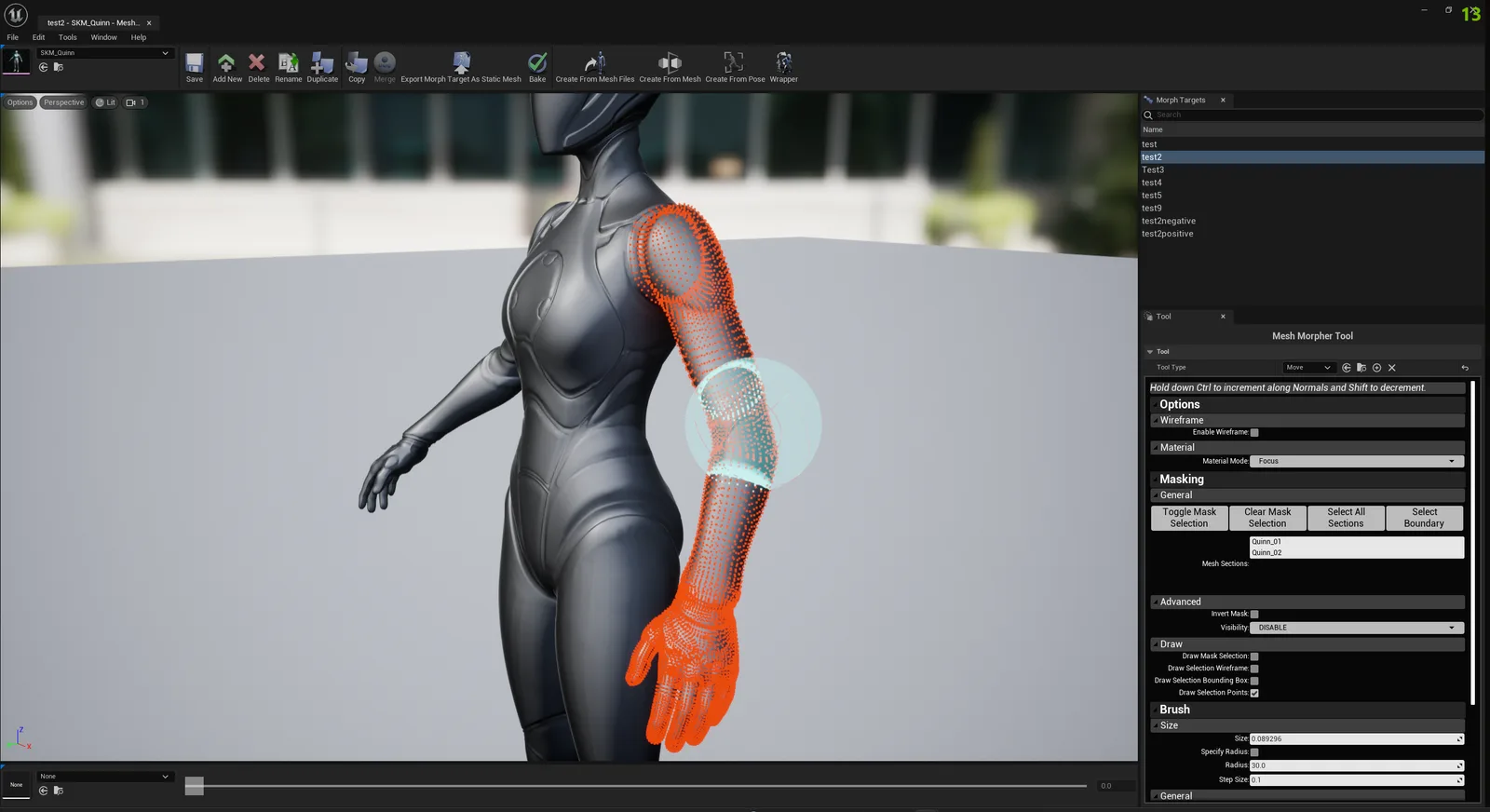













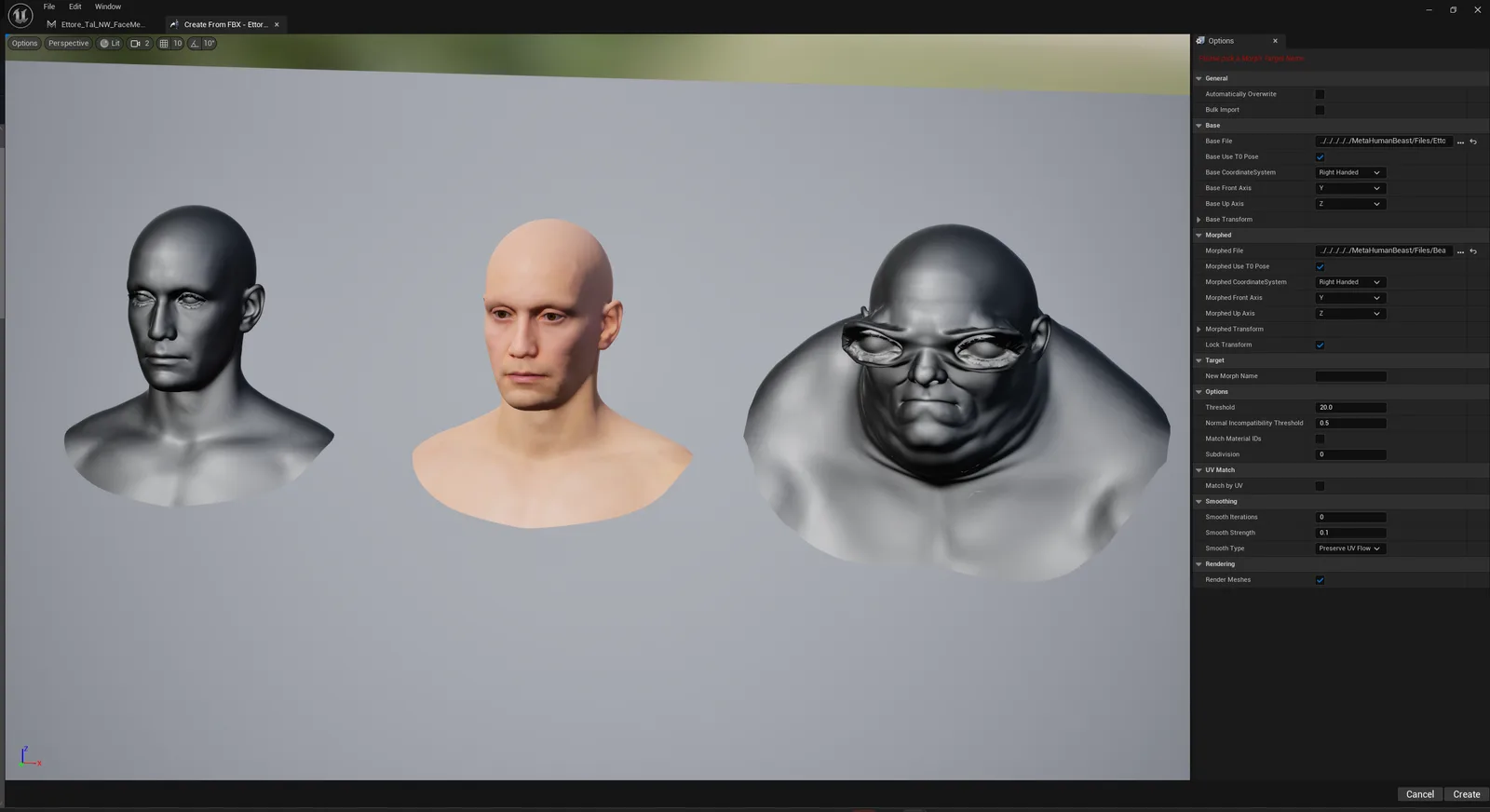
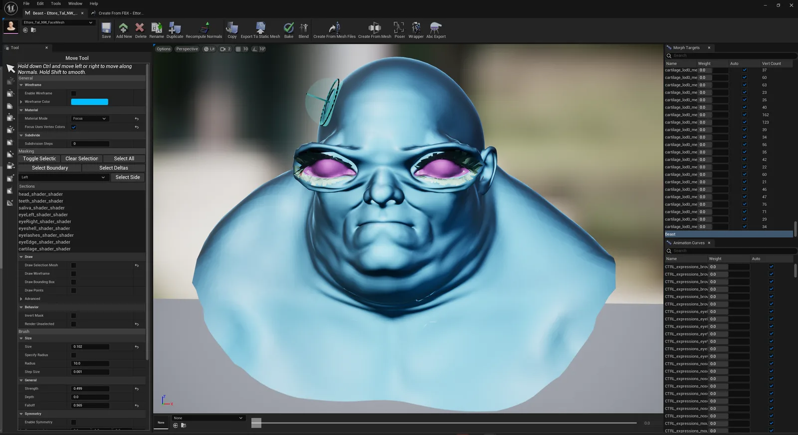
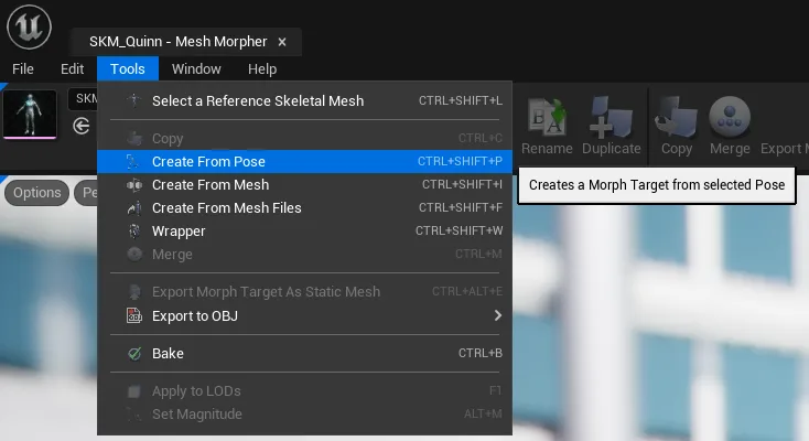
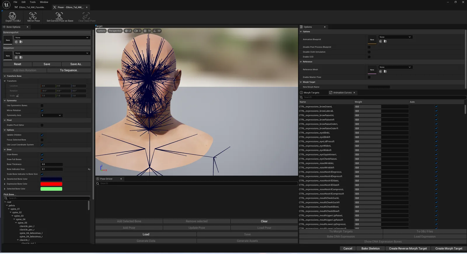
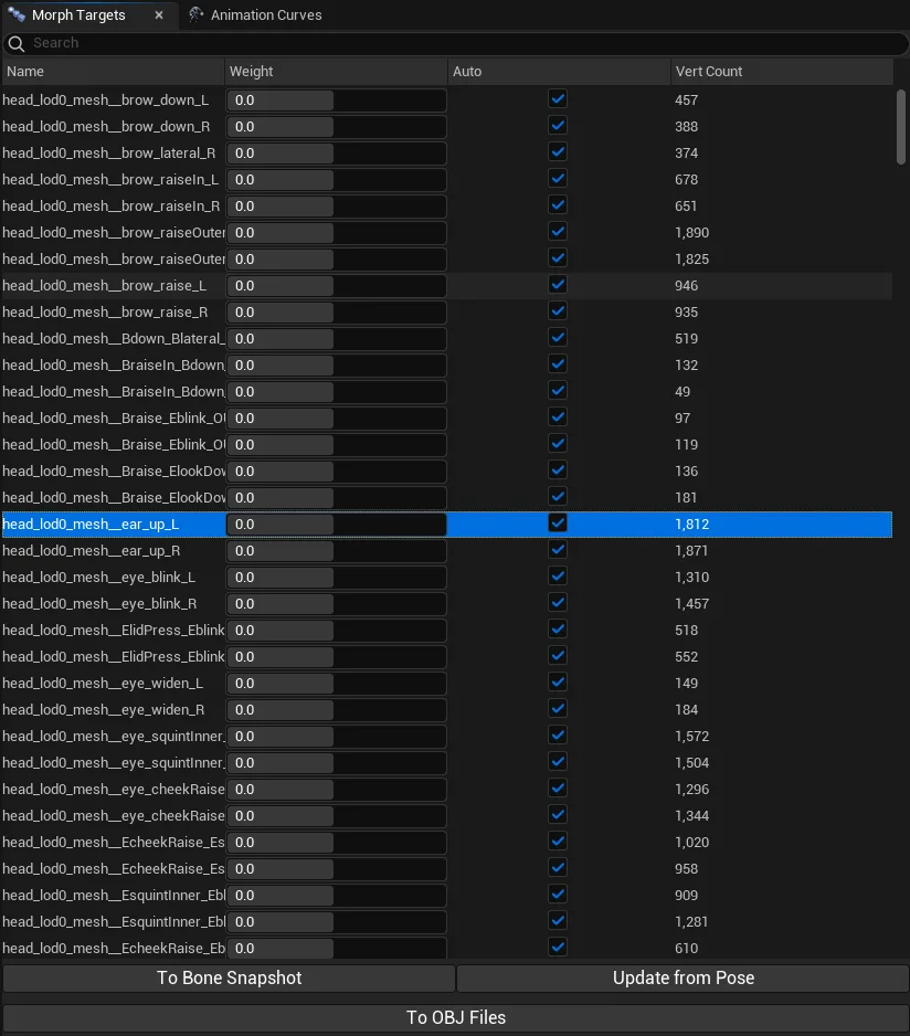
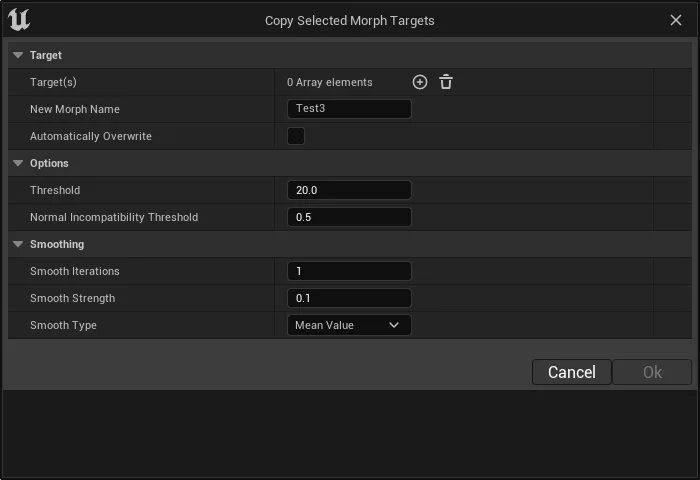
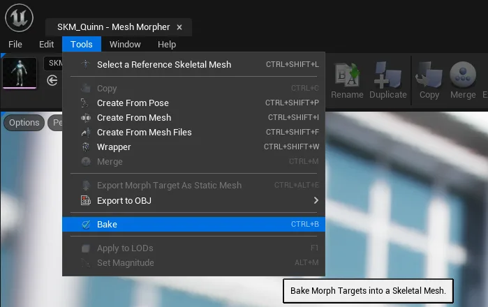
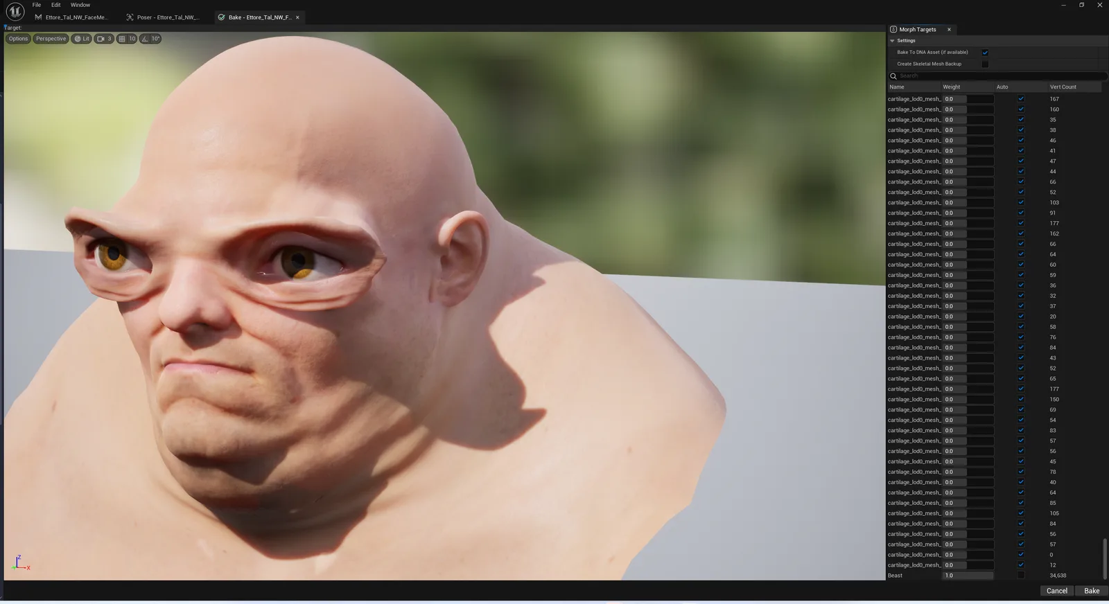
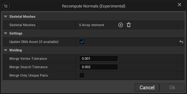
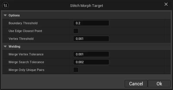
Mesh Morpher allows you to create/remove/modify, copy, import and export morph targets easily from within Unreal Engine Editor.
Mesh Morpher allows you to create/remove/modify, copy, import and export morph targets easily from within Unreal Engine Editor. Mesh Morpher version 2.0 and above is only available for UE5.0 and later. Mesh Morpher doesn't use any third party libraries outside the engine.
A Morph Target is a snapshot of vertex locations for a specific mesh that have been deformed in some way. For instance, you can take a character model, reshape their face to create a facial expression, and then save that edited version as a Morph Target.
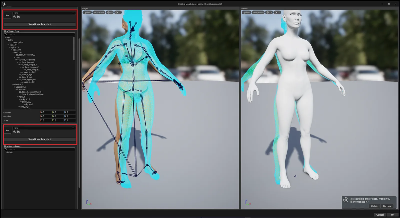
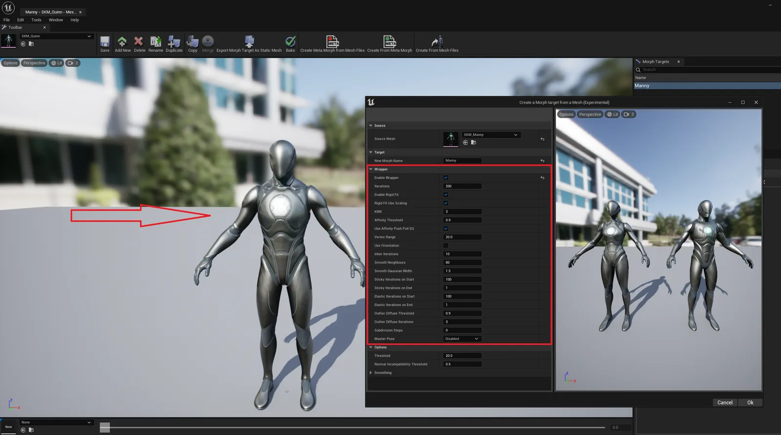
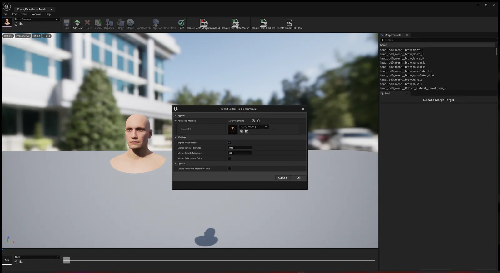
Mesh Morpher allows users to create Morph Targets using various tools, from sculpting, importing from FBX/OBJ files to Wrapping to other Skeletal Meshes.
Mesh Morpher was awarded a Mega Grant by Epic Games which helped with the development in its initial stage.
[MM-1276] Fixed a bug in 5.8 where Mesh Morpher would use legacy dna wrongfully
Mesh Morpher 5.2.3 is Live! (06/17/2026)
[MM-1274] Cleaned shaders and changed threadgroup to 256
Mesh Morpher 5.2.2.1 is Live! (04/07/2026)
[MM-1273] Fixed the progress bar in nonrigid fit
Mesh Morpher 5.2.2 is Live! (04/01/2026)
[MM-1272] Greatly improved non-rigid algorithm
Mesh Morpher 5.2.1.1 is Live! (02/27/2026)
[MM-1271] Fixed a bug with UV mapping in Control Points where mapping would correctly place control points when the mesh had multiple UDIMS
Mesh Morpher 5.2.1 is Live! (02/26/2026)
[MM-1268] Wrapper now supports static meshes both as source and target
[MM-1269] Elastic Conformer now supports static meshes both as source and target
[MM-1270] Control Points in Wrapper now support UV mapping.
Mesh Morpher 5.2.0 is Live! (02/22/2026)
[MM-1267] Fixed a bug where the corrective morph targets wouldn't get highlighted when a DNA expression is selected.
Mesh Morpher 5.1.9 is Live! (02/20/2026)
[MM-1264] Fixed a bug in Geometry Cache sculpting where UVs wouldn't be properly loaded
[MM-1265] Fixed a bug in Animation Sequence sculpting where materials wouldn't be properly loaded.
[MM-1266] Fixed a bug with Static Mesh sculpting where sculpting with "only connected" enabled wouldn't work.
Mesh Morpher 5.1.8 is Live! (02/20/2026)
[MM-1258] Geometry Cache and animation sequence sculpting settings are now persistent.
[MM-1259] Geometry Cache sculpting now work in with welded meshes to avoid gaps at UV seams.
[MM-1260] Geometry Cache sculpting now supports non-constant topology
[MM-1261] Improved delta rotation in Geometry Cache sculpting.
[MM-1262] Fixed a bug in geometry cache and animation sculpting where the materials wouldn't load
[MM-1263] Fixed a bug in geometry cache sculpting where sculpting with "only connected" enabled wouldn't work.
Mesh Morpher 5.1.7.1 is Live! (02/15/2026)
[MM-1257] Implemented parallelization in geometry cache sculpting and animation sequence sculpting.
Mesh Morpher 5.1.7 is Live! (02/15/2026)
[MM-1256] Sculpting Geometry caches and animation sequences now correctly apply delta rotation when sculpting frame ranges.
Mesh Morpher 5.1.6 is Live! (02/13/2026)
[MM-1255] Fixed a possible LOD bug in Alembic Export, Delta Mush animation correction and Graph toolkit.
Mesh Morpher 5.1.5 is Live! (02/13/2026)
[MM-1242] Implemented Delta Mush Tool
[MM-1243] Implemented Delta Mush for Animation Sequences
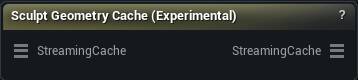
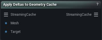
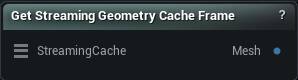
[MM-1244] Implemented the ability to sculpt geometry caches
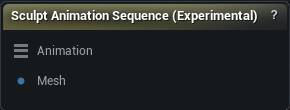
[MM-1245] Implemented the ability to sculpt animation sequences
[MM-1246] Implemented the ability to sculpt static meshes
[MM-1247] Fixed GPU Solver in Non-Rigid Fit
[MM-1248] Wrapper/Elastic Conformer have persistent settings
[MM-1249] Alembic Exporter default transformation now correctly matches Blender
[MM-1250] Implemented Frame Range widget in Alembic Exporter
[MM-1251] Alembic Exporter can now export frame ranges
[MM-1252] Various code clean-ups and optimizations
[MM-1253] Fixed toolkit tab name bug in Classic
[MM-1254] Fixed a bug in Mesh Morpher Classic where we incorrectly forward declare FAnimInstanceProxy
Mesh Morpher 5.1.4 is Live! (02/09/2026)
[MM-1238] Implemented the ability to change light angle in all viewports.
[MM-1239] Implemented the ability to display Content Browser in mesh morpher with ctrl + spacebar.
[MM-1240] Implemented GPU solver in Mesh Morpher
[MM-1241] Fixed a bug where the chlomod dlls wouldn't properly load when the plugin was installed in the engine directory.
Mesh Morpher 5.1.3 is Live! (02/05/2026)
[MM-1237] Fixed a bug where mesh morpher would crash the engine due to registering itself in persona windows without morph target tabs
Mesh Morpher 5.1.2 is Live! (01/26/2026)
[MM-1234] Implemented Import Organization Data
[MM-1235] Implemented Export Organization Data
[MM-1236] Fixed various performance bugs in Organization Data
Mesh Morpher 5.1.1 is Live! (01/25/2026)
[MM-1227] Implemented Meta data for Morph Target and Animation curve lists
[MM-1228] Rename Morph Target now supports regex
[MM-1229] Rename Morph Target now supports bulk rename
[MM-1230] Implemented custom Morph Target viewer in Persona
[MM-1231] Improved Non Rigid Fit
[MM-1232] Improved Rigid Fit
[MM-1233] Fixed Toolkit focus.
Mesh Morpher 5.1.0 is Live! (01/02/2026)
[MM-1225] Improved PoseDeltas to work correctly with inverse quaternions when bone rotations are involved.
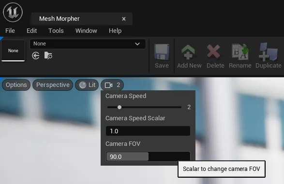
[MM-1226] Viewport saves/loads camera settings
Mesh Morpher 5.0.9 is Live! (12/28/2025)
[MM-1223] Added new Non Rigid Fit algorithm
[MM-1224] Old NonRigidFit algorithm is renamed to Elastic Conformer.
Mesh Morpher 5.0.8 is Live! (12/07/2025)
[MM-1220] Fixed a possible crash in Mesh Morpher Mesh Component where FindingNearestTriangles might return invalid triangle ids and crash
[MM-1221] Alembic Exporter now writes FaceSets
[MM-1222] Alembic Exporter now computes Normals
Mesh Morpher 5.0.7.2 is Live! (12/04/2025)
[MM-1219] Fixed symmetry with Connected vertices ROI in sculpt tools.
Mesh Morpher 5.0.7.1 is Live! (12/04/2025)
[MM-1217] Fixed the ability to switch symmetry in sculpting tools
[MM-1218] Symmetry default value changed to X axis in sculpting tools
Mesh Morpher 5.0.7 is Live! (12/04/2025)
[MM-1214] Greatly Improved Alembic Exporter
[MM-1215] Transform Tool now updated mesh bounds so it renders properly
[MM-1216] Fixed symmetry in sculpting tools
Mesh Morpher 5.0.6 is Live! (12/03/2025)
[MM-1213] Fixed Symmetry in Mesh Morpher Mesh Component
Mesh Morpher 5.0.5 is Live! (12/02/2025)
[MM-1212] Greatly improved Alembic Exporter
Mesh Morpher 5.0.4 is Live! (11/29/2025)
[MM-1206] Alembic export now uses import data
[MM-1207] Alembic export now holds some additional meta data
[MM-1208] Implemented Geometry Cache Validation functionality which aims to match the Geometry Cache track names with material names.
[MM-1209] Alembic export now preserve the animation sequence frame rate
[MM-1210] Fixed a bug where last frame in the alembic export would be skipped
[MM-1211] Fixed some UV issues across Mesh Morpher
[MM-1212] Fixed a bug in Alembic Preview where seeking backwards would crash
Mesh Morpher 5.0.3 is Live! (11/14/2025)
[MM-1203] Runtime Projector now works the same as In-Editor.
[MM-1204] Fixed a bug with Runtime Projector where applying deltas to higher LODs wouldn't correctly work
[MM-1205] Fixed Camera Speed for 5.7 and above
Mesh Morpher 5.0.2 is Live! (11/05/2025)
[MM-1202] Implemented Unpack RigLogic functionality in poser (5.6 and above)
Mesh Morpher 5.0.1 is Live! (10/30/2025)
[MM-1201] Improved Project Tool
Mesh Morpher 5.0.0 is Live! (10/29/2025)
[MM-1197] Improved performance of all sculpting tools
[MM-1198] Implemented throttling for handle based tools
[MM-1199] Implemented Transparent Material Mode for sculpting tools.
[MM-1200] Fixed a bug with handle based tools that would cause a silent crash when toggling selection mode or when switching to other tool
Mesh Morpher 4.9.9 is Live! (10/15/2025)
[MM-1196] Implemented Post-Processing in Wrapper which solves intersections with the Source
Mesh Morpher 4.9.8 is Live! (10/13/2025)
[MM-1195] Implemented the ability to remove RBF data in Transfer DNA.
Mesh Morpher 4.9.7 is Live! (10/08/2025)
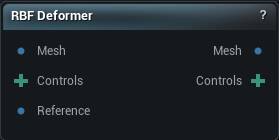
[MM-1194] Improved RBF deformer
Mesh Morpher 4.9.6 is Live! (10/06/2025)
[MM-1191] Improved Mirror Tool
[MM-1192] Fixed getting Normals in MM Mesh Component
[MM-1193] Greatly Improved Project Tool
Mesh Morpher 4.9.5 is Live! (10/03/2025)
[MM-1188] Improved Wrapper and landmark system in Wrapper drastically
[MM-1189] Improved the speed of FBX importer
[MM-1190] Fixed Mesh Import for runtime
Mesh Morpher 4.9.4 is Live! (09/29/2025)
[MM-1187] Implemented the ability to re-create DNA expression animation curves
Mesh Morpher 4.9.3 is Live! (09/25/2025)
[MM-1182] Removed Ray Tracing option
[MM-1183] Fixed a possible bug in Mesh Streaming was sending a 1-byte heartbeat that could make the client disconnect
[MM-1184] Improved Non_rigid fitting
[MM-1185] Non-Rigid fit speed has been improved by a lot
[MM-1186] Simplified Non-Rigid fitting options.
Mesh Morpher 4.9.2 is Live! (09/22/2025)
[MM-1173] Fixed a bug in Scene Proxy for Mesh Component
[MM-1174] Fixed a bug in Mesh Component when recomputing Normals
[MM-1175] Fixed a bug in OBJ exporter where unused empty UVs and Normals where added
[MM-1176] Vectorized Wrapper Rigid and Non-Rigid fit functionality
[MM-1177] Improved Regular smoothing in Non-Rigid Fit
[MM-1178] Implemented Point-To-Plane projection in Wrapper
[MM-1179] Implemented Displacement clamping in Non-Rigid fit which aims to reduce irrelevant correspondences.
[MM-1180] Improved the overall speed of Non-Rigid Fit algorithm
[MM-1181] Updated Mesh Stream icon
Mesh Morpher 4.9.1 is Live! (09/18/2025)
[MM-1172] Implemented Guide Morph Target in Copy Morph Targets
Mesh Morpher 4.9.0 is Live! (09/15/2025)
[MM-1171] Fixed FBX Importer to load only LOD0 for meshes exported by blender
Mesh Morpher 4.8.9 is Live! (09/15/2025)
[MM-1167] Fixed OBJ exporter. Now it correctly exports UV and Normal Layouts and not causing issues anymore with welded meshes.
[MM-1168] Greatly Improved FBX/OBJ importer
[MM-1169] Added parallelism in FBX importer
[MM-1170] Improved DNA export to OBJ to respect UV and Normal layouts
Mesh Morpher 4.8.8 is Live! (09/12/2025)
[MM-1164] Copy Morph Target now has the ability to auto-scale transferred morph targets
[MM-1165] Greatly improve Copy Morph Targets
[MM-1166] Implemented Copy Delta Method. Additive and Replace ('Replace' is more robust, while 'Additive' is faster but assumes similar base meshes.)
Mesh Morpher 4.8.7 is Live! (09/07/2025)
[MM-1163] Fixed a bug that would apply the deformation coming from Mesh Stream twice, making the process slow.
Mesh Morpher 4.8.6 is Live! (09/07/2025)
[MM-1161] Implemented Mesh Streaming Tool
[MM-1162] Fixed a bug where loading an RBF Controls asset would crash if canceled.
Mesh Morpher 4.8.5 is Live! (08/23/2025)
[MM-1160] Fixed a bug where DNA blendshapes wouldn't be correctly saved
Mesh Morpher 4.8.4 is Live! (07/23/2025)
[MM-1154] Implemented the ability to switch LODs
[MM-1155] Implemented the ability to Sculpt LODs
[MM-1156] Implemented the ability to overwrite LODs with Create from Mesh Files
[MM-1157] Implemented the ability to export mesh LODs and Animation Curves applied to LODs
[MM-1158] Implemented the ability to export texture masks for LODs
[MM-1159] Improved Lock Camera in Wrapper
Mesh Morpher 4.8.3 is Live! (07/18/2025)
[MM-1147] Implemented feature aware correspondence finder in Wrapper.
[MM-1148] Implemented density aware correspondence finder in Wrapper.
[MM-1149] Implemented subdivision in Wrapper.
[MM-1150] Removed sampling from Wrapper.
[MM-1151] Implemented Anisotropic smoothing in Wrapper.
[MM-1152] GREATLY improved performance and quality in Wrapper.
[MM-1153] Simplified options in Wrapper. Now settings are more user-friendly.
Mesh Morpher 4.8.2 is Live! (07/11/2025)
[MM-1146] Handle body DNA correctly in 5.6
Mesh Morpher 4.8.1 is Live! (06/04/2025)
[MM-1145] DNA Compatibility with 5.6
Mesh Morpher 4.8.0 is Live! (05/26/2025)
[MM-1142] Fixed a possible bug with Inlier Finder in Wrapper
[MM-1143] Implemented the ability to load only rotations from bonesnapshots in Poser
Mesh Morpher 4.7.9 is Live! (05/25/2025)
[MM-1140] Changed the default Landmark Weight in Wrapper to 100
[MM-1141] Implemented Convert DNA expressions in Poser which allows us to convert expressions from one skeleton hierarchy to another.
[MM-1142] Fixed KNN in Wrapper`s Affine Transformation
Mesh Morpher 4.7.8 is Live! (05/24/2025)
[MM-1137] Wrapper has greatly improved rigid fitting
[MM-1138] Wrapper has greatly improved non-rigid fitting
[MM-1139] Landmark system in Wrapper has been greatly improved
Mesh Morpher 4.7.7 is Live! (05/19/2025)
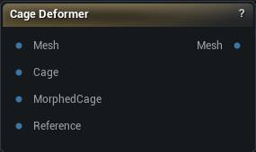
[MM-1136] Implemented Cage Deformer Tool
Mesh Morpher 4.7.6 is Live! (05/16/2025)
[MM-1135] Fixed a possible bug in RBF Deformer Tool that would crash the engine due to NaN transformation in certain cases.
Mesh Morpher 4.7.5 is Live! (05/16/2025)
[MM-1134] RBF Deformer Tool Transform gizmo now updates every frame instead of the end of transformation.
Mesh Morpher 4.7.4 is Live! (05/16/2025)
[MM-1133] RBF Deformer tool now supports full transformations. location, rotation, scale.
Mesh Morpher 4.7.3 is Live! (05/15/2025)
[MM-1127] Implemented Symmetry in RBF Deformer tool
[MM-1128] Implemented the ability to load/save RBF Control Points
[MM-1129] Implemented the ability to save pose as RBF Control Points asset
[MM-1130] RBF Deformer now has the ability to work with vertex selection
[MM-1131] RBF Deformer now has the ability to ignore boundary vertices
[MM-1132] Improve undo/redo system in RBF Deformer Tool
Mesh Morpher 4.7.2 is Live! (05/09/2025)
[MM-1126] Implemented new Skeleton Fitting algorithm that handles scaled down deformations much better.
Mesh Morpher 4.7.1 is Live! (05/01/2025)
[MM-1124] Mirroring Tool now has the ability to average the selected neighbors amount to the mirrored position. This allows for non-symmetric topologies to be mirrored at the cost of losing a little bit of detail due to averaging.
[MM-1125] Gaussian Kernel in RBF Deformer is now Local Kernel, as intended.
Mesh Morpher 4.7.0 is Live! (04/28/2025)
[MM-1123] Fixed Control Point creation in RBF Deformer in UE 5.5
Mesh Morpher 4.6.9 is Live! (04/28/2025)
[MM-1119] Implemented RBF Deformer sculpting tool
[MM-1120] Implemented rotation in Lattice deformer
[MM-1121] Wrapper has different vertex range variable for non-rigid and rigid fit
[MM-1122] bUpdateDNAAssetBlendshapes is enabled by default
Mesh Morpher 4.6.8 is Live! (04/20/2025)
[MM-1115] Improved Control Points(Landmarks) in Wrapper
[MM-1116] Improved Wrapper algorithm
[MM-1117] Implemented IDW in Wrapper to propagate deformation to different resolution mesh
[MM-1118] Implemented the ability to find correspondences in non-rigid algorithm in wrapper based on the Source mesh Surface.
Mesh Morpher 4.6.7 is Live! (04/17/2025)
[MM-1114] Fixed a bug with Transform Tool where Mesh Morpher would crash if the tool was open with a selection
Mesh Morpher 4.6.6 is Live! (04/14/2025)
[MM-1110] Bone widget now displays index as well
[MM-1111] Improved Transform Tool
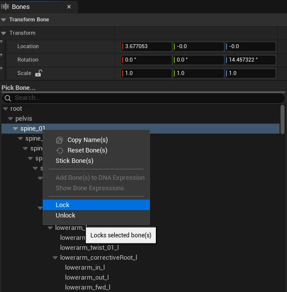
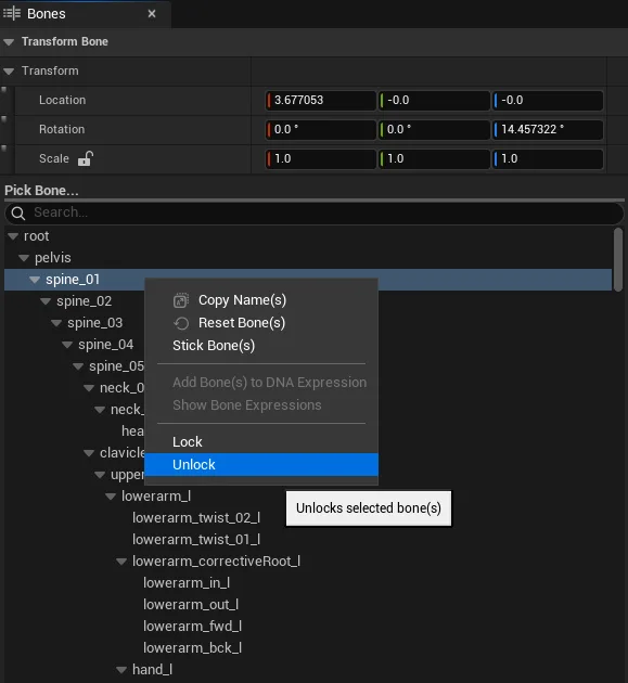
[MM-1112] Implemented the ability to Lock/Unlock bones in poser
[MM-1113] Creating new Morph Target shortcut(Ctrl + A) has been changed to Ctrl + Alt + A
Mesh Morpher 4.6.5 is Live! (04/08/2025)
[MM-1107] Improved creating DNA Expressions from Morph Targets
[MM-1108] Added the ability in Poser to disable re-inserting missing rotation attributes when Baking Expressions
[MM-1109] Having a Morph Target and Expression Curve selected when opening Create DNA Expression will not attempt to automatically match all other expressions
Mesh Morpher 4.6.4 is Live! (04/05/2025)
[MM-1106] Implemented the ability to Preserve Location in Blend Tool
Mesh Morpher 4.6.3 is Live! (04/04/2025)
[MM-1100] Removed Invert Masking Boolean
[MM-1101] Implemented Invert Selection
[MM-1102] Implemented Smoothing Outskirts in Restore Side and Manual Restore (Not Relative restore)
[MM-1103] Implemented Smoothing Outskirts in Transform Tool
[MM-1104] Implemented Smoothing Outskirts in Blend Tool
[MM-1105] Improved Undo/Redo in Transform Tool
Mesh Morpher 4.6.2 is Live! (03/25/2025)
[MM-1098] Fixed a possible crash when trying to save a morph target on a mesh with corrupted import data
[MM-1099] Implemented Inverse Skinning in wrapper
Mesh Morpher 4.6.1 is Live! (03/14/2025)
[MM-1096] Implemented Map asset for Create DNA Expression from Morph Target
[MM-1097] Create DNA Expression from Morph Target now first search for matching Morph Targets
Mesh Morpher 4.6.0 is Live! (03/13/2025)
[MM-1089] Implemented the ability to add DNA Bones to Expressions
[MM-1090] Implemented the ability to view all expressions associated with DNA Bones
[MM-1091] Fixed a possible DNA bug where adding rotations to certain bones and expressions wouldn't work due to DNA pruning
[MM-1092] Show DNA Expressions Bones now displays the bones in Bone List in Poser
[MM-1093] Implemented the ability to bulk Create DNA expressions
[MM-1094] Added Toolbar button and icon for Create DNA Expression from Morph Target
[MM-1095] Added asset icons and thumbnail for Bonesnapshot, Standalone Morph Target and Standalone Mask Selection
Mesh Morpher 4.5.9 is Live! (03/02/2025)
[MM-1088] Create DNA Expressions now has the ability to automatically bake the DNA expression
Mesh Morpher 4.5.8 is Live! (02/26/2025)
[MM-1082] Added an UV sampler as a secondary failover on UV Matching across Mesh Morpher
[MM-1083] Fixed a bug with material in Append Mesh
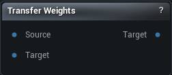
[MM-1084] Transfer Weights now allows to transfer weights to meshes based on Closest Point and UV Matching
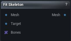
[MM-1085] Transfer Weights now allows to fit skeleton based on the new weights
[MM-1086] Transfer Weights now also transfers DNA asset, post process blueprint and default animation rig
[MM-1087] Transfer Weights now has persistent settings.
Mesh Morpher 4.5.7 is Live! (02/24/2025)
[MM-1079] Implemented Transfer Weights by UV Match in Append Mesh
[MM-1080] Baking grooms now checks for decimation settings in Groom Asset. If decimation values are not 1.0 then baking gets skipped
[MM-1081] Improved Matching By UV across Mesh Morpher. Vertices with no exact UV match are now UV projected to find their correspondence
Mesh Morpher 4.5.6 is Live! (02/18/2025)
[MM-1077] Implemented undo/redo for irreversible functions
[MM-1078] Implemented the ability to manually check for updates
Mesh Morpher 4.5.5 is Live! (02/16/2025)
[MM-1074] Fixed a bug with delete Morph target
[MM-1075] Fixed a bug with rename Morph target
[MM-1076] Added undo/redo for Morph Target operations
Mesh Morpher 4.5.4 is Live! (02/13/2025)
[MM-1072] Fixed a possible issue with Rename Morph Targets
[MM-1073] Fixed possible crashes across Mesh Morpher
Mesh Morpher 4.5.3 is Live! (02/13/2025)
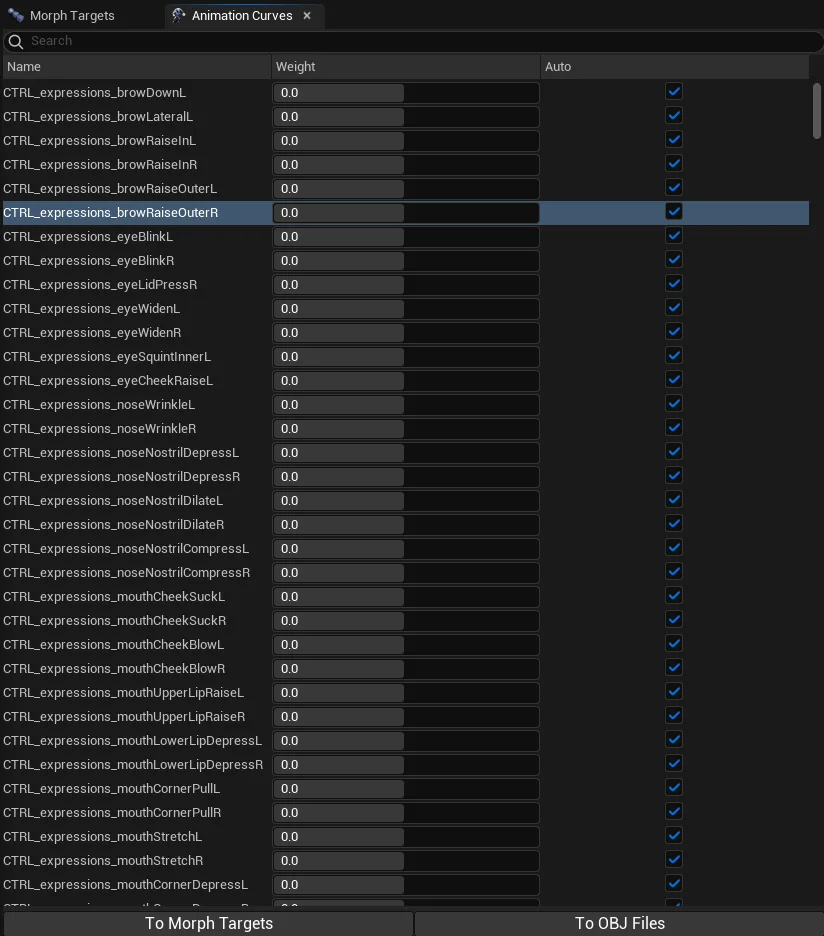
[MM-1070] Implemented the ability to add animation curves
[MM-1071] Implemented the ability to remove selected animation curves
[MM-1002] Create from FBX now fully works with Corrective Morph Targets
[MM-1003] Capturing Skeletal Mesh Components now fully works with Corrective Morph Targets
[MM-1004] Implemented the option to load Morph Target in or without pose.
Mesh Morpher 4.2.9 is Live! (12/14/2024)
[MM-995] Improved Copy Morph Target algorithm
[MM-996] Copy Morph Target now allows target selections assets.
[MM-997] Fixed a bug in To Mesh Deformer where Mesh Morpher would crash due to wrong vertex indices passed
[MM-998] Implemented the ability to create a Morph Target from current render state on selected component in sequencer/levelviewport
[MM-999] Create a Deformer Graph that can be assigned to skeletal meshes to apply deformations post skinning
Mesh Morpher 4.2.8 is Live! (12/11/2024)
[MM-988] Implemented the ability to bake to Skeleton Asset
[MM-989] Implemented the ability to not load driven bones when loading Pose Drivers from Anim BP
[MM-990] Implemented the ability to move Up and Down Pose drivers in the list
[MM-991] Implemented the ability to write Morph Targets to Pose Drivers
[MM-992] Load Pose Drivers from Anim BP has new dialog window
[MM-993] Save Pose Drivers to Anim BP has new dialog window
[MM-994] Fixed a bug where selecting a bone from the viewport wouldn't automatically scroll to it in the bone list.
Mesh Morpher 4.2.7 is Live! (12/07/2024)
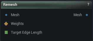
[MM-987] Fixed Remesh to Target Edge Length
Mesh Morpher 4.2.6 is Live! (12/05/2024)
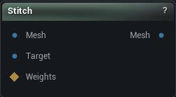
[MM-986] Implemented the ability to stitch meshes and morph targets by Bone Weights. This assumes the boundary vertices of the meshes already have the correct topology and bone weights and that at some point they were playing nice together. This new functionality has been tested with Meta Humans only and it doesn't work with different body types. It's intended to repair meta humans and not extend them to automatically stitch head to different body types or vice versa.
Mesh Morpher 4.2.5 is Live! (12/01/2024)
[MM-985] Fixed a bug in Create Morph Target from Mesh.
Mesh Morpher 4.2.4 is Live! (11/24/2024)
[MM-983] Exporting to OBJ from Poser now exports render data.
[MM-984] Fixed a bug with Copy Morph Target that would crash Mesh Morpher in certain cases.
Mesh Morpher 4.2.3 is Live! (11/12/2024)
[MM-981] Bone List in Poser now has its own Tab. This allows for better access and interaction with skeletons.
[MM-982] Sculpt Tools now display specific properties in a separate movable widget.
Mesh Morpher 4.2.2 is Live! (11/07/2024)
[MM-979] Fixed a bug where selecting a DNA expression wouldn't mark it's correspondent Morph Target if the Morph Target was empty
[MM-980] Fixed a bug where saving an empty Morph Target wouldn't go through.
Mesh Morpher 4.2.1 is Live! (10/31/2024)
[MM-974] Implemented the ability to set Magnitude to DNA expressions
[MM-975] Fixed a possible crash in Remove Mesh Data
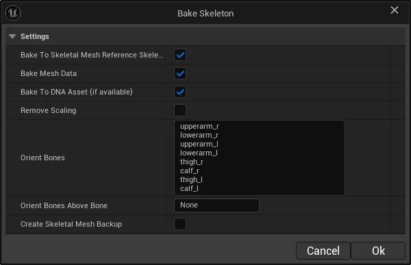
[MM-976] Bake Skeleton in Poser has been renamed to Bake
[MM-977] Bake Morph Target has been removed. Poser can be used to Bake Morph Targets
[MM-978] Fixed an issue where Mesh Morpher would crash when saving morph targets for meshes that have vertices with no triangles
Mesh Morpher 4.2.0 is Live! (10/29/2024)
[MM-971] Fixed a bug Bake Skeletal Mesh where baking would sometimes offset the mesh
[MM-972] Fixed a bug Bake Skeleton in Poser where baking would sometimes offset the mesh
[MM-973] Implemented the ability to load Post Process animation blueprint with rotation only
Mesh Morpher 4.1.9 is Live! (10/23/2024)
[MM-970] Morph Target to Bonesnapshot is using again Render Data due to the fact that some skeletal meshes(meta human bodies as well) can have corrupted import data.
Mesh Morpher 4.1.8.3 is Live! (10/20/2024)
[MM-968] Fixed a possible bug where subdividing a mask selection with boundary edges would crash Mesh Morpher
[MM-969] Fixed a bug where exporting a Morph Target with no deltas with export an empty file instead of the neutral mesh.
Mesh Morpher 4.1.8.2 is Live! (10/19/2024)
[MM-967] Fixed a possible bug that would crash Mesh Morpher when loading skeletal meshes with corrupted triangle data.
Mesh Morpher 4.1.8.1 is Live! (10/18/2024)
[MM-965] Fixed a bug in 5.5 Preview 1 that prevented settings to be saved.
[MM-966] Fixed various small bugs across Mesh Morpher
Mesh Morpher 4.1.8 is Live! (10/18/2024)
[MM-962] Fixed a bug in Append Meshes where when multiple meshes were appended at once the weights would be transferred only to the first one.
[MM-963] Loading Pose Drivers from Anim BP now loads the neutral pose from skeletal mesh.
[MM-964] Saving Pose Drivers now makes sure no duplicate curve names are generated.
Mesh Morpher 4.1.7.1 is Live! (10/09/2024)
[MM-961] Loading Pose Drivers from Anim BP now correctly adds rotation to the source bone even when the pose drivers assets don't match the skeletal mesh.
Mesh Morpher 4.1.7 is Live! (10/08/2024)
[MM-957] Implemented the ability to update neutral poses in pose drivers for selected post process anim bp
[MM-958] Implemented the ability to load in Poser pose drivers from selected post process anim bp
[MM-959] Improved the saving of pose drivers to animation blueprints
[MM-960] Morph Target to Bonesnapshot now uses import data
Mesh Morpher 4.1.6.1 is Live! (10/07/2024)
[MM-956] Fixed a bug with alembic support in UE 5.4 and above
Mesh Morpher 4.1.6 is Live! (10/06/2024)
[MM-955] Internally Mesh Morpher now uses import data and on export render data
Mesh Morpher 4.1.5 is Live! (10/05/2024)
[MM-952] Fixed a bug with Remove from Mesh where bone weights wouldn't be correctly Removed.
[MM-953] Standalone Selection now works correctly in Remove From Mesh and Remesher.
[MM-954] Fixed a newly introduced bug that prevented saving setting and patch notifications.
Mesh Morpher 4.1.4 is Live! (10/04/2024)
[MM-948] Huge Refactoring on the underlying morph target and baking functionality in UE 5.4 and above. This refactoring should ease up further development.
[MM-949] Fixed a bug that would crash Mesh Morpher when generating a bonesnapshot from a morph target and the skeleton would contain virtual bones.
[MM-950] Implemented the ability to generate an Animation Sequence with random poses for ML Deformer
[MM-951] Morph Target LOD projection now uses only Closest Neighbor
UE 5.2 and 5.3 are now in Legacy support.
Mesh Morpher 4.1.3 is Live! (09/30/2024)
[MM-946] Implemented the ability to mark and focus associated corrective morph targets for Meta Human expressions
[MM-947] In poser, enabling an animation curve will not reset the Morph Targets
Mesh Morpher 4.1.2 is Live! (09/27/2024)
[MM-944] Implemented the ability to re-orient bones on Bake Skeleton in Poser
[MM-945] Implemented the ability to stick bones to the closest bone segment in Poser
Mesh Morpher 4.1.1 is Live! (09/23/2024)
[MM-941] Append Mesh now has a preview
[MM-942] Implemented the ability in Append Mesh to transform appended meshes
[MM-943] Improved Bone Orientation in Morph Target to Bonesnapshot
Mesh Morpher 4.1.0 is Live! (09/19/2024)
[MM-938] Remove Section is now called Remove Mesh Data
[MM-939] Implemented the ability to remove standalone selection in Remove Mesh Data
[MM-940] Implemented the ability to preview in Remove Mesh Data
Mesh Morpher 4.0.9 is Live! (09/14/2024)
[MM-936] Implemented the ability to recalculate bone orientation in Morph Target to Bonesnapshot
[MM-937] Implemented the ability to set a bone where recalculating orientation stops in Morph Target to Bonesnapshot
Mesh Morpher 4.0.8 is Live! (09/09/2024)
[MM-932] Implemented the ability to load Bonesnapshots in Bone space.
[MM-933] Fixed a bug with frame number text input in main window which didn't allow to correctly scroll through frames.
[MM-934] Implemented a slider in Poser which allows to navigate through animation sequences directly.
[MM-935] Implemented the ability to update a frame in an animation sequence.
Mesh Morpher 4.0.7 is Live! (09/04/2024)
[MM-926] Subdivision now has Preview
[MM-927] Greatly improved subdivision algorithm
[MM-928] Implemented Remesher
[MM-929] Smooth Tool now can automatically ignore boundary vertices
[MM-930] Projecting Morph Targets has been slightly improved
[MM-931] Fixed some possible crashes with Mesh Morpher Mesh Component
Mesh Morpher 4.0.6 is Live! (08/20/2024)
[MM-925] Implemented the ability to Hide sections in Sculpting Tools.
Mesh Morpher 4.0.5 is Live! (07/27/2024)
[MM-921] Implemented Grab Sculpt Tool


[MM-922] Implemented Scale Sculpt Tool

[MM-923] Implemented Twist Sculpt Tool
[MM-924] Implemented Sculpt tool falloff types
Mesh Morpher 4.0.4 is Live! (07/26/2024)
[MM-919] Implemented the ability to load a bonesnapshot with Pivot Editor enabled
[MM-920] Slightly improved Spike Smoother in Laplacian Smooth Tool
Mesh Morpher 4.0.3 is Live! (07/16/2024)
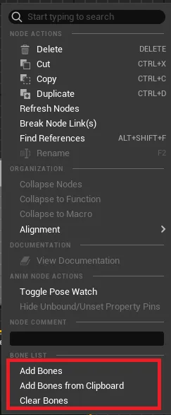
[MM-916] Added menu to RigLogicNoBones node
[MM-917] Implemented the ability to paste bones from clipboard in RigLogicNoBone node
[MM-918] Implemented the ability to clear selected bones in RigLogicNoBone node
Mesh Morpher 4.0.2 is Live! (07/15/2024)
[MM-915] Added the ability in RigLogic anim node to select bones to ignore
Mesh Morpher 4.0.1 is Live! (07/14/2024)
[MM-911] Blend Sculpt tool now has 3 Blend Types: Replace, Append and Subtract
[MM-912] Move Tool now correctly moves along the Normals
[MM-913] Fixed a bug with export animation curves with bone movement to morph targets or obj files where the export in certain cases wouldn't be completely accurate.
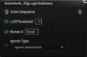
[MM-914] Implemented a new animation node Anim Node Rig Logic No Bones which is a variant of the engine's Rig Logic node but without any bone movement.
Mesh Morpher 4.0.0 is Live! (07/12/2024)
[MM-904] Fixed a bug that would crash the engine on close when Mesh Morpher was opened with additional viewport windows(Poser etc)
[MM-905] Implemented the ability to transform bone selection in Poser.
[MM-906] Set Pivot from Selected Section now supports multiple bone selection
[MM-907] Add axis rotation now supports multiple bone selection
[MM-908] Adding Selected Bones to Pose Driver now supports multiple bone selection
[MM-909] Fixed a bug that wouldn't close the child Windows on Skeletal Mesh change
[MM-910] Transform Widget in Poser now supports Local and World Transforms
Mesh Morpher 3.9.9 is Live! (07/10/2024)
[MM-901] Implemented MoveCurvesToSkeleton
[MM-902] Implemented MoveCurvesToMesh
[MM-903] Fixed a newly introduced bug in 5.2 that wouldn't open the sculpting tools when a morph target was selected
Mesh Morpher 3.9.8.1 is Live! (07/09/2024)
[MM-900] Fixed a bug where windows with viewports wouldn't be properly cleaned up resulting in gpu memory getting filled
Mesh Morpher 3.9.8 is Live! (07/09/2024)
[MM-898] Reset in Poser now correctly reset bones
[MM-899] Fixed a bug where the meta human dna would cache only morph targets containing deltas.
Mesh Morpher 3.9.7 is Live! (07/05/2024)
[MM-895] Fixed a bug where baking DNA Mesh data wouldn't write correct normals
[MM-896] DNA To OBJ now exports section names
[MM-897] Implemented the ability to set scale and color on DNA to OBJ export
Updater.exe has been compiled now for x64 allowing bigger downloads. (Requires package download from website)
Mesh Morpher 3.9.6 is Live! (07/05/2024)
[MM-894] Implemented the ability to export DNA asset to OBJ
Mesh Morpher 3.9.5 is Live! (07/02/2024)
[MM-889] Implemented Blend Sculpt Tool
[MM-890] Baking DNA Bone Expression attempts to rebuild the mesh
[MM-891] Implemented the ability to Reset bone selection
[MM-892] Fixed a bug where Control Points and Ruler Points would not be rendered correctly with DPI Scale
[MM-893] Slightly improved the speed of wrapper
Mesh Morpher 3.9.4 is Live! (06/25/2024)
[MM-887] Greatly improved Wrapping algorithm
[MM-888] Fixed a newly introduced bug with Copy Morph Targets
Mesh Morpher 3.9.3 is Live! (06/24/2024)
[MM-882] Expression Bones are now color coded in the Bone List as well
[MM-883] Baking Meta Human Heads now automatically attempts to fix eye pivot bones. This can be Disabled in Bake Skeleton window.
[MM-884] Enabling an Animation curves now refreshes and resets enabled Morph Targets.
[MM-885] Add Morph Target now allows multiple row input enabling multiple morph target creation at once.
[MM-886] Fixed a bug on Mac where selecting a file in Create from Mesh File would hang the engine
Mesh Morpher 3.9.2 is Live! (06/14/2024)
[MM-878] Bone Transform Widget in Poser now allows copy and paste
[MM-879] Fixed a bug that would crash the engine when Bone Options Tab was hidden and then shown again in Poser
[MM-880] Advanced Fitting settings are now persistent
[MM-881] Implemented a Toolbar in Poser
Mesh Morpher 3.9.1 is Live! (06/13/2024)
[MM-876] Fixed a bug with Flatten Tool
[MM-877] Fixed a bug with Plane Tool
Mesh Morpher 3.9.0 is Live! (06/12/2024)
[MM-875] Implemented Advanced Bone Fitting for DNA Bone Expressions
Mesh Morpher 3.8.9 is Live! (06/12/2024)
[MM-873] Improved Mirroring Morph Targets
[MM-874] Fixed a possible crash in 5.4.2
Mesh Morpher 3.8.8 is Live! (06/10/2024)
[MM-869] Updated icon colors
[MM-870] Selected DNA bone expression now have their affected bones color coded
[MM-871] Fixed a bug in Remove Section where changing the LOD index wouldn't always refresh the list with the LOD sections
[MM-872] Bake DNA Expression now asks for confirmation
Mesh Morpher 3.8.7 is Live! (06/08/2024)
[MM-867] Greatly improved Meta Human DNA Bone Expressions Baking
[MM-868] Implemented the ability to move a bone without affecting its children
Mesh Morpher 3.8.6 is Live! (06/07/2024)
[MM-862] Fixed a bug that would crash the Engine on shutdown after Mesh Morpher was opened (UE 5.4.2).
[MM-863] Ability to write to dna file the bone expression changes.
[MM-864] Implemented the ability to Load Expression which loads from a bonesnapshots only the bones associated with the expression.
[MM-865] Implemented the ability to update DNA bone expression from a bonesnapshot
[MM-866] Updated UI theme (Thanks to Yassine Rahal)
Mesh Morpher 3.8.5.2 is Live! (06/06/2024)
[MM-861] Fixed a bug where DNA Bone expression changes wouldn`t be correctly calculated.
Mesh Morpher 3.8.5.1 is Live! (06/05/2024)
[MM-860] DNA Bone Expression changes can be exported to dna file
Mesh Morpher 3.8.5 is Live! (06/05/2024)
[MM-858] Implemented the ability to modify and bake DNA expressions (bone expressions)
[MM-859] Implemented the ability to display bones affected by DNA expression
Mesh Morpher 3.8.4 is Live! (06/03/2024)
[MM-852] Implemented the ability to Mirror Morph Targets
[MM-853] Implemented the ability to Mirror Poses
[MM-854] Implemented the ability to set End Bone on Bonesnapshot save
[MM-855] Implemented the ability to Remove Sections(experimental)
[MM-856] Alembic exporter now captures cloth simulation
[MM-857] Alembic exporter now captures physics simulation
Mesh Morpher 3.8.3 is Live! (05/23/2024)
[MM-849] Implemented Fix Spikes in Laplacian Smooth tool
[MM-850] Alembic exporter now captures curves from animation sequence.
[MM-851] Mesh Morpher now displays animation curves from skeletal meshes as well instead of only from skeleton
Mesh Morpher 3.8.2 is Live! (05/16/2024)
[MM-846] Implemented another layer of poses to be loaded. Users can now load Bonesnapshots and Sequences simultaneously. This should allow for extra possibilities when creating correctives for more complex poses.
[MM-847] Alembic Exporter now evaluates animation sequence completely.
[MM-848] Changing Pose or Reference Mesh now asks if the current opened Morph Target(if any) should be saved.
Mesh Morpher 3.8.1 is Live! (05/07/2024)
[MM-845] Fixed a bug with stitching
Mesh Morpher 3.8.0 is Live! (05/07/2024)
[MM-844] Modal windows now automatically scale based on resolution
Mesh Morpher 3.7.9 is Live! (05/05/2024)
[MM-842] Improved OBJ exporter
[MM-843] Improved OBJ importer
Mesh Morpher 3.7.8 is Live! (05/01/2024)
[MM-841] Fixed a possible bug with Recompute Normals where applying new normals would crash in certain cases after a mesh was appended.
Mesh Morpher 3.7.7 is Live! (05/01/2024)
[MM-838] Implemented a workaround for 5.4 bug with Persona that doesn't clear correctly its binding when the Persona window is closed. This resulted in a crash on mesh rebuild.
[MM-839] There is a new MaxKNN option in Edit->Settings that attempts to speed up the projection in certain operations. Higher values would mean more time to project.
[MM-840] Fixed a bug in Append Mesh where each LOD iteration would attempt to rebuild the mesh.
Mesh Morpher 3.7.6 is Live! (04/30/2024)
[MM-836] Improved Append Mesh
[MM-837] Fixed Transform tool bug where it wouldn't work correctly while scaling and rotating with preserve pivot point enabled.
Mesh Morpher 3.7.5 is Live! (04/30/2024)
[MM-834] Subdivision and Mesh Append now preserve correctly all attributes.
[MM-835] Implemented a possible fix for engine crash when mesh gets rebuild while opened in Persona
Mesh Morpher 3.7.4 is Live! (04/29/2024)
[MM-831] Implemented the ability to export Quad OBJs
[MM-832] Fixed a bug with Lattice Deformer Tool where the normals and spatial data wouldn't be regenerated on undo/redo
[MM-833] Fixed a bug with Transform Tool where the normals and spatial data wouldn't be regenerated on undo/redo
Mesh Morpher 3.7.3.1 is Live! (04/26/2024)
[MM-830] Fixed a bug with stitching where stitching wouldn't correctly work with enabled morph targets on reference mesh and when the delta vertices moved the boundary vertices away from their location..
Mesh Morpher 3.7.3 is Live! (04/25/2024)
[MM-824] Stitching now correctly recomputes normals
[MM-825] Stitching now preserves settings
[MM-826] Append mesh now preserves settings
[MM-827] Recompute Normals now preserves settings
[MM-828] Subdivide now preserves settings
[MM-829] Laplacian Smoothing now preserves settings
Mesh Morpher 3.7.2 is Live! (04/23/2024)
[MM-816] Improved Subdivision
[MM-817] Implemented Laplacian and Corrective Smoothing
[MM-818] Implemented the ability to subdivide selected sections
[MM-819] Improved the speed of ICP algorithm for certain operations
[MM-820] Improved Stitch Morph Target algorithm
[MM-821] Stitch Morph Target can now position on the closest edge. Useful for meshes with different vertex density.
[MM-822] Implemented the ability to merge skeletons
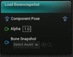
[MM-823] Load Bonesnapshot node is now available in Control Rig as well (only 5.4 and as experimental as it gets)
Mesh Morpher 3.7.1 is Live! (04/13/2024)
[MM-812] Fixed a newly introduced bug that would prevent getting correct correspondent from skeletal to welded mesh
[MM-813] OBJ export now exports per section color if selected
[MM-814] Fixed a bug that would prevent correct bulk animation curve export
[MM-815] Mesh Morpher can now be packaged in 5.4
Mesh Morpher 3.7.0 is Live! (04/12/2024)
[MM-810] Fixed a bug where Displace Tool would not correctly load Platform Data for certain texture formats.
[MM-811] Changed the Transfer Weight defaults on Subdivide Mesh to generate more accurate bone weight data.
Mesh Morpher 3.6.9 is Live! (04/10/2024)
[MM-806] Implemented the ability to subdivide meshes (5.4 and above)
[MM-807] Implemented Displace Tool
[MM-808] Implemented the ability to not apply Morph Targets to LODs.
[MM-809] Greatly improved the speed at which the resulted morph targets from sculpt tools are applied to the mesh. This should help working with high density meshes.
Mesh Morpher 3.6.8 is Live! (04/08/2024)
[MM-801] Implemented the ability to append meshes and transfer bone weights to new mesh data
[MM-802] Implemented the ability to transfer weights to another compatible skeletal mesh
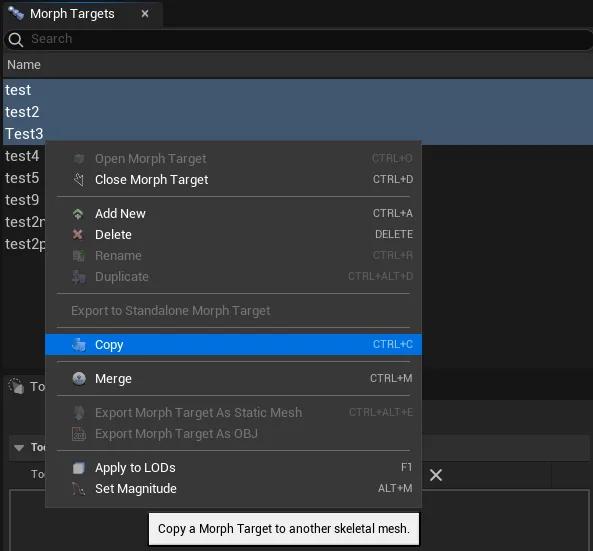
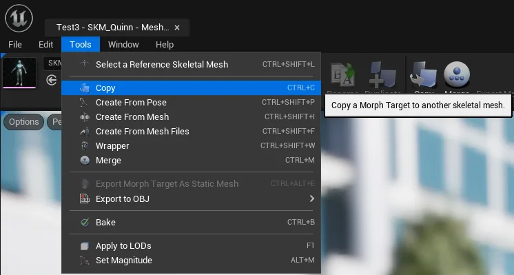
[MM-803] Implemented the ability to copy morph targets from source with post process enabled or disabled
[MM-804] Fixed a possible bug with OBj export that might give unexpected results when subdivision steps higher than 0
[MM-805] Fixed a possible bug that would crash Mesh Morpher if opening Recompute Normals once the window was already open
Mesh Morpher 3.6.7.1 is Live! (03/31/2024)
[MM-800] Fixed a bug with Projection tool where projection wouldn't correctly work in certain cases.
Mesh Morpher 3.6.7 is Live! (03/29/2024)
[MM-797] Fixed a bug where commiting an animation curve value would reset it back to the original value
[MM-798] Added extra refining option to Morph Target to Bonesnapshot functionality
[MM-799] Morph Target to Bonesnapshot now has persistent settings
Mesh Morpher 3.6.6.1 is Live! (03/28/2024)
[MM-796] Improved bone fitting
Mesh Morpher 3.6.6 is Live! (03/28/2024)
[MM-795] Implementing the ability to create a Bonesnapshot for skeletal and reference skeletal mesh in Poser. The morph target has to have the same name on both meshes.
Mesh Morpher 3.6.5 is Live! (03/22/2024)
[MM-787] Requires re-entering license key. License information can be found in Saved\Config\WindowsEditor\MeshMorpher.ini file now (remove it from there if sharing the project)
[MM-788] Cleaned up the code
[MM-789] Implemented UObject smart pointers
[MM-790] Greatly improved skeleton fitting
[MM-791] Skeleton fitting allows fitting based on bone weights
[MM-792] Skeleton fitting allows fitting based on surface bones
[MM-793] Removed baking to skeleton asset
[MM-794] Fixed a possible issue that could crash when writing to dna asset with no geometry
Mesh Morpher 3.6.4 is Live! (03/20/2024)
[MM-786] Fixed a problem that could occur with Alembic Export.
Mesh Morpher 3.6.3 is Live! (03/20/2024)
[MM-785] Fixed a possible bug that could prevent bone updating in alembic export
Mesh Morpher 3.6.2 is Live! (03/18/2024)
[MM-783] Fixed a bug where exporting animation curves and morph targets by right clicking on the curve list, would export an obj with deltas from post process enabled mesh and default mesh
[MM-784] Implemented the ability to quickly disable post process in main toolkit
Mesh Morpher 3.6.1 is Live! (03/17/2024)
[MM-778] Dynamic Skeletal Mesh Component now have Set Bone Delta and Get Bone Delta functionality
[MM-779] Implemented the ability to create Texture Masks from Selection
[MM-780] Implemented the ability to bake Pivot editor to reference mesh in Poser
[MM-781] Implemented the ability to create Bonesnapshot from Reference Mesh in Poser
[MM-782] Fixed a potential memory leak in Create from Mesh Files
Mesh Morpher 3.6.0 is Live! (03/12/2024)
[MM-777] Fixed baking with removed scale
Mesh Morpher 3.5.9 is Live! (03/11/2024)
[MM-772] Loading Bonesnapshot now resets existing deltas
[MM-773] Fixed a bug where bone transforms would append post process changes
[MM-774] Fixed a bug where pivot editor bone transforms would append post process changes
[MM-775] Creating Bonesnapshots from Morph Target now allows a vertex sample to compute deltas
[MM-776] Saving Bonesnapshots now make sure post process is not part of the deltas.
Mesh Morpher 3.5.8.1 is Live! (03/09/2024)
[MM-771] Implemented the ability in Dynamic Skeletal Mesh Component in Load Bonesnapshot to skip deltas for bones that exists in leader pose components.
Mesh Morpher 3.5.8 is Live! (03/09/2024)
[MM-770] Implemented runtime DynamicSkeletalMeshComponent which enables bone transformation for blueprints at runtime for Skeletal Mesh Components.
Mesh Morpher 3.5.7.3 is Live! (03/07/2024)
[MM-768] Appended Meshes to OBJ Exports now have post process blueprints applied to them
[MM-769] Creating a Morph Target from an animation curve now doesn't contain any post process results
Mesh Morpher 3.5.7.2 is Live! (03/07/2024)
[MM-766] Fixed a newly introduced bug where loading Pose Driver Poses wouldn't work
[MM-767] Fixed a newly introduced bug where loading bone transformations in Deformer Graph wouldn't work.
Mesh Morpher 3.5.7.1 is Live! (03/06/2024)
[MM-765] On Bake reset bone deltas
Mesh Morpher 3.5.7 is Live! (03/06/2024)
[MM-764] Fixed possible issues and artifacts that could occur when Baking and Post Process blueprints would transform bones.
Mesh Morpher 3.5.6 is Live! (03/06/2024)
[MM-762] Improved how Mesh Morpher handles post process blueprints
[MM-763] Blend Morph Targets takes into account post process to avoid additional possible deltas.
Mesh Morpher 3.5.5 is Live! (03/05/2024)
[MM-754] Implemented subdivision for OBj exports
[MM-755] Improved save assets dialog.
[MM-756] Animation Sequences and Pose Assets can be overwritten.
[MM-757] Reference mesh in Poser can only be a skeletal mesh
[MM-758] Implemented the ability in Poser to set leader pose for reference skeletal mesh.
[MM-759] Animation Sequences and Pose Assets editors close automatically on save.
[MM-760] Implemented the ability to save pose drivers to pose assets only without writing to animation blueprint
[MM-761] Fixed a bug where Load Pose from Context menu in Pose Driver would instead Update the Pose.
Mesh Morpher 3.5.4 is Live! (03/01/2024)
[MM-752] Alembic Exporter now provides different transform options.
[MM-753] Alembic exporter now correctly export unmirrored mesh data
Mesh Morpher 3.5.3 is Live! (02/26/2024)
[MM-749] Fixed mesh component to work properly with post process allowing users to load poses in post process and work correctly with them in Mesh Morpher
[MM-750] Animation curves don't get automatically set to 0 on create/delete/modify morph target
[MM-751] Implemented the ability in Load Bonesnapshot to enable/disable applying bones to parent shared bones.
Mesh Morpher 3.5.2.1 is Live! (02/18/2024)
[MM-748] Fixed a newly introduced bug that wouldn't allow users to select vertices further from current selection.
Mesh Morpher 3.5.2 is Live! (02/18/2024)
[MM-747] Transform Tool can now preserve pivot point on rotation
Mesh Morpher 3.5.1 is Live! (02/17/2024)
[MM-740] Fixed a bug that crashed Mesh Morpher when baking skeleton with virtual bones added.
[MM-741] Implemented the ability to simulate physics in Poser. Simulation can be disabled from Edit->Settings->bDisablePhysics
[MM-742] Implemented the ability to enable/disable Cloth Simulation in Poser
[MM-743] Implemented the ability to enable/disable CCD for all bodies in Poser
[MM-744] Implemented the ability to send a posed mesh to Deformer Graph allowing to apply deformer graphs to it and save it as a Morph Target. (>= 5.3)
[MM-745] Implemented the ability to send from Poser to Deformer Graph (>= 5.3)
[MM-746] Fixed a bug with sculpting tools where HitTesting selection wouldn't correctly ignore unwanted triangles.
Mesh Morpher 3.5.0 is Live! (02/11/2024)
[MM-739] Implemented a new Load Bonesnapshot node that doesn't run in Component Space. The old node is still available and is marked as (Legacy)
Mesh Morpher 3.4.9 is Live! (02/09/2024)
[MM-736] Scaling with Transform Tool now preserve pivot point.
[MM-737] Transform Widget is synced with the Gizmo.
[MM-738] Fixed Camera Speed Scalar.
Mesh Morpher 3.4.8.1 is Live! (02/08/2024)
[MM-735] Fixed a newly occurring bug that prevented saving changes in morph targets.
Mesh Morpher 3.4.8 is Live! (02/07/2024)
[MM-728] Improved performance of sculpting tools
[MM-729] Removed refinement from sculpt tools
[MM-730] Enabled Mode overrides for Mesh Morpher Component
[MM-731] Implemented Ray Tracing in Mesh Morpher Component
[MM-732] Improved performance of Transaction system(undo/redo)
[MM-733] Implemented Pen Pressure in Sculpting Tools.
[MM-734] Implemented the ability to enable/disable ray tracing for sculpting from Editor->Settings (requires Mesh Morpher restart)
Mesh Morpher 3.4.7 is Live! (02/01/2024)
[MM-727] Implemented the ability to create corrective bonesnapshots
Mesh Morpher 3.4.6 is Live! (01/31/2024)
[MM-720] Improved wrapper control points system.
[MM-721] Fixed a bug where loading a morph target would reload the mesh in other related tools like wrapper and poser.
[MM-722] Simplified Wrappers options so it's much easier to configure it
[MM-723] Added additional options to Non rigid wrapping that allow selection of vertex range and orientation separately from rigid settings.
[MM-724] Fixed a bug where changing source mesh in wrapper would attempt to notify all mesh morpher windows.
[MM-725] Optimized and fixed non rigid registration in wrapper.
[MM-726] Implemented Scale to OBJ export
Mesh Morpher 3.4.5 is Live! (01/12/2024)
[MM-712] Implemented the ability to Bulk Import from OBJ/FBX
[MM-713] Fixed a bug with Morph Target to Bonesnapshot that prevented to correctly calculate the bones above ignore bones in the hierarchy
[MM-714] Wrapper Target mesh gets divided and refined. Increased the vertex threshold to 5.0
[MM-715] Update From Pose in Poser now allows to update Morph Targets with Base from other Morph Targets or Animation Curves
[MM-716] Exporting to Animation Sequence now exports Morph Targets and Animation Curves with selected Weights
[MM-717] Implemented the ability to reset Weight Values to curve selection in Curve Lists.
[MM-718] Fixed a Bug where Morphed Directory would be disabled by default even though bulk import was enabled on Load Settings in Create From Mesh Files.
[MM-719] Automatically Overwrite in Create from Mesh Files now works for single file import as well.
Mesh Morpher 3.4.4 is Live! (01/07/2024)
[MM-709] Fixed a bug where smoothing in Sculpt, Pinch and Inflate wouldn't get registered for undo/redo.
[MM-710] Improved Tool subdivision
[MM-711] Implemented new Material mode Tension which allows to visualize per vertex stretch and compression.
Mesh Morpher 3.4.3 is Live! (01/06/2024)
[MM-697] Transform Tool now places the gizmo in the center of selection automatically.
[MM-698] Added key shortcut (B) that allows to dynamically change brush size moving mouse left and right
[MM-699] Added key shortcut (N) that allows to dynamically change brush falloff moving mouse left and right
[MM-700] Added key shortcut (S) that allows to dynamically change brush strength moving mouse left and right
[MM-701] Added remesher for sculpt tool
[MM-702] Added remesher for inflate tool
[MM-703] Added remesher for pinch tool
[MM-704] Moving along the normals now requires holding CTRL and moving left and right
[MM-705] Fixed a bug where falloff was inverted in sculpting tools
[MM-706] Fixed a bug where grabbing vertex ROI in sculpting tools wouldn't use full brush radius
[MM-707] Moving vertices along the Normal doesn't use falloff anymore
[MM-708] Step Size has been set to 0.001 by default in Sculpting Tools
Mesh Morpher 3.4.2 is Live! (01/05/2024)
[MM-691] Fixed a bug where Exporting a selection to OBJ wouldn't properly append additional meshes.
[MM-692] Fixed a bug that prevented cached mesh data update when exporting animation curves to obj in main toolkit.
[MM-693] Exporting to OBJ now automatically creates new sections for additional meshes
[MM-694] Ruler doesn't get enabled automatically on tool shutdown
[MM-695] Greatly improved the animation curve system in main toolkit.
[MM-696] Greatly improved the morph target system in main toolkit.
Mesh Morpher 3.4.1 is Live! (01/04/2024)
[MM-685] Optimized Sculpting Tools
[MM-686] Fixed a bug that wouldn't properly render a mesh section if material was null
[MM-687] Implemented the Ability to render section colors in Sculpt Tools
[MM-688] Revamped the rendering of Mesh Morpher Mesh Component
[MM-689] Revamped selection in Mesh Morpher Mesh Component
[MM-690] Added the ability to project on selected target sections.
Mesh Morpher 3.4.0.2 is Live! (12/31/2023)
[MM-681] Applying Smoothing to selection now correctly stores the action for Undo/Redo
[MM-682] Implemented the ability to subdivide projection target
[MM-683] Implemented Projection iterations
[MM-684] Implemented Projection Smoothing
Mesh Morpher 3.4.0.1 is Live! (12/30/2023)
[MM-679] Fixed a bug with Project tool when failing to project would provide a NaN vector
[MM-680] Fixed a possible bug with Smoothing while attempting to preserve volume.
Mesh Morpher 3.4.0 is Live! (12/30/2023)
[MM-671] Implemented the ability to Apply Smoothing Tool to selection or full mesh
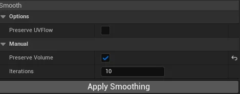
[MM-672] Implemented the ability to set smoothing iteration in Apply Smoothing(manual)
[MM-673] Implemented the ability to preserve volume in Apply Smoothing(manual)
[MM-674] Implemented Project Tool which allows users to project on Reference Skeletal Mesh
[MM-675] Implemented the ability to Apply Restore Tool to selection or full mesh
[MM-676] Implemented the ability to preserve location in Apply Restore(manual)
[MM-677] Subdividing on Copy Morph Target applies refinement to source subdivide mesh.
[MM-678] Stitching doesn't create a seam anymore. We just stitch boundary vertices.
Mesh Morpher 3.3.9 is Live! (12/27/2023)
[MM-669] Fixed a bug where removing an enabled Morph Target wouldn't recreate the dynamical meshes internally
[MM-670] Improved asset picker performance while loading assets in Poser and Toolkit
Mesh Morpher 3.3.8 is Live! (12/26/2023)
[MM-668] Fixed a bug with overwriting bonesnapshots, rulers, pose drivers and control points assets
Mesh Morpher 3.3.7 is Live! (12/24/2023)
[MM-664] Fixed a bug that prevented bone list refresh on source mesh selection in Wrapper
[MM-665] Improved wrapping algorithm by refining subdivided source mesh.
[MM-666] Implemented the ability to set Max Sticky and Elastic Iterations in Wrapper
[MM-667] Fixed a bug that didn't update selected morph target pointer when refreshing morph target list.
Mesh Morpher 3.3.6 is Live! (12/21/2023)
[MM-663] Fixed a bug that prevented Morph Target export when exporting selection from Morph Targets list
Mesh Morpher 3.3.5 is Live! (12/18/2023)
[MM-658] Implemented the ability to remove Driven Bones in Pose Driver Creator
[MM-659] Selecting sequence and bonesnapshots has been improved in Poser and Wrapper
[MM-660] Loaded sequences in Poser now use Frame Index rather than frame time to provide better precision and accuracy when navigating through the sequence.
[MM-661] Implemented the ability to enable/disable Ruler
[MM-662] Ruler is disabled by default
Mesh Morpher 3.3.4 is Live! (12/18/2023)
[MM-657] Implemented the ability to mirror Pose Driver bones in Poser.
Mesh Morpher 3.3.3 is Live! (12/17/2023)
[MM-655] Implemented the ability to switch Poser transform gizmo from world to local coordinate system.
[MM-656] Fixed a bug that would prevent Pose Driver nodes created procedurally by Mesh Morpher to display correctly debug data.
Mesh Morpher 3.3.2 is Live! (12/16/2023)
[MM-651] Fixed a bug that would crash Mesh Morpher when selecting reference mesh and setting the master pose type to reference.
[MM-652] Fixed a bug that would export inverted Alembic.
[MM-653] Implemented the ability to exported flattened Alembic
[MM-654] Implemented the ability to add a child component in ABC exporter. Child gets own abc file.
Mesh Morpher 3.3.1 is Live! (12/15/2023)
[MM-650] Added the ability to enable curves and morph targets in main toolkit window, thus allowing us to easily sculpt correctives.
Mesh Morpher 3.3.0 is Live! (12/11/2023)
[MM-643] Implemented Add Axis Rotation in Poser
[MM-644] Bonesnapshot menu works with pivot editor enabled
[MM-645] Loading Sequences and Bonesnapshots now disable each other. Can't have both simultaneously.
[MM-646] Implement the ability to pick assets and overwrite them
[MM-647] Fixed a possible bug with undo/redo bone transforms
[MM-648] Implemented the ability to create Pose Drivers with Poser
[MM-649] Implemented the ability to export a pose to a Sequence
Mesh Morpher 3.2.9 is Live! (12/08/2023)
[MM-640] Fixed a bug in LOD baking when Baking Skeleton
[MM-641] Implemented the ability to ignore weighted bones when creating Bonesnapshot from Morph Target
[MM-642] Implemented the ability to select multiple bones and copy names of the selection
Mesh Morpher 3.2.8.2 is Live! (12/07/2023)
[MM-639] Improved alembic exporter
Mesh Morpher 3.2.8.1 is Live! (12/07/2023)
[MM-638] Fixed a bug with alembic exporter where certain animations would be exported with wrong bone transformations
Mesh Morpher 3.2.8 is Live! (12/07/2023)
[MM-630] Improved Morph Target to Bonesnapshot algorithm
[MM-631] Implemented the ability to match bones by vertex weight(Useful for big meshes like bodies) in Morph Target to Bonesnapshot
[MM-632] Implemented the ability to ignore bones containing strings(can use multiple strings divided by ;) in Morph Target to Bonesnapshot
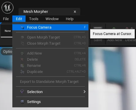
[MM-633] Improved Focus at Cursor.
[MM-634] Implemented Focus at Cursor in Sculpting Tools
[MM-635] Implemented Focus at Cursor in Wrapper
[MM-636] Implemented Focus at Cursor in Poser
[MM-637] Implemented Alembic Exporter(can export skeletal meshes and sequences to abc)
Mesh Morpher 3.2.7.1 is Live! (11/28/2023)
[MM-629] Fixed a bug that would crash when in Blend, Bake Morph Target and Select Reference Mesh and a curve was enabled
Mesh Morpher 3.2.7 is Live! (11/27/2023)
[MM-627] Implemented Rigid Fitting in Wrapper which allows us to match rotation and scale of the source
[MM-628] Greatly improved Wrapper algorithm
Mesh Morpher 3.2.6 is Live! (11/25/2023)
[MM-620] Implemented Ruler in Poser
[MM-621] Implemented Ruler in Sculpt Tools
[MM-622] Fixed a bug with Wrapper that would project distorted resulted deltas back to the initial mesh
[MM-623] Fixed a bug with Wrapper where Mesh Morpher would crash when initializing with Pivot Editor enabled
[MM-624] Load Save and Save As Bonesnapshot menu button are disabled when Pivot Editor is enabled.
[MM-625] Removed Inverse Matching from Wrapper
[MM-626] Standalone selection assets now store identical mesh indices
Mesh Morpher 3.2.5 is Live! (11/19/2023)
[MM-612] Implemented Pivot Editor in Poser
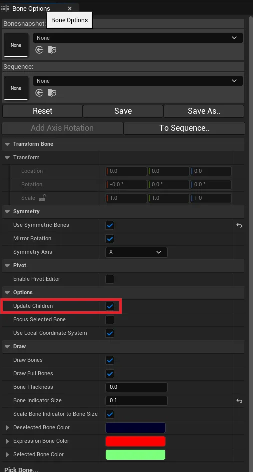
[MM-613] Implemented the ability to Update Children in Pivot Editor
[MM-614] Improved Bone Editor performance in Poser
[MM-615] Fixed a bug where selecting a bug in Poser while symmetry is enabled would automatically attempt to rotate the symmetric bone
[MM-616] Improved bone undo/redo in Poser
[MM-617] Fixed a bug with Set Pivot Bone from Section where the Mesh wouldn't correctly translate with new bone transforms.
[MM-618] Implemented the ability to enable/disable Update Children in Set Pivot Bone from Section
[MM-619] Set Pivot Bone menu entry has been renamed to Set Pivot Bone from Section
Mesh Morpher 3.2.4 is Live! (11/16/2023)
[MM-608] Fixed a bug where changing between Sculpt Tools wouldn't reselect the mesh sections in the section list if any selection was made.
[MM-609] Implemented the ability to Set Animation Curves in Toolkit Main window.
[MM-610] Implemented the ability to Set Morph Targets in Toolkit Main window.
[MM-611] Poser now doesn't use Main Toolkit pose as base pose. Instead it only uses the Base Pose set from the Poser.
Mesh Morpher 3.2.3.1 is Live! (11/12/2023)
[MM-606] Fixed a bug where DNA asset blendshapes updates wouldn't be correctly stored
[MM-607] Disabling Mesh Data Bake will not bake Mesh Data to DNA asset
Mesh Morpher 3.2.3 is Live! (11/11/2023)
[MM-603] Implemented the ability to modify Meta Human blendshapes and export them to DNA asset.
[MM-604] Exporting to DNA asset now exports spine_04 translation
[MM-605] Greatly improved the speed of baking in Poser and Bake Morph Targets.
Mesh Morpher 3.2.2 is Live! (11/10/2023)
[MM-602] Improved speed of bulk Morph Target copy.
Mesh Morpher 3.2.1 is Live! (11/09/2023)
[MM-600] Implemented Clipping fix for Restore Tool. This functionality tries to move the vertices over the closest triangle. Could provide better results in certain cases.
[MM-601] Implemented the Ability to set pivot bone to mesh section selection
Mesh Morpher 3.2.0 is Live! (11/02/2023)
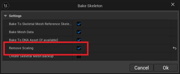
[MM-598] Implemented the ability to remove Scaling when Baking to Skeleton. This will preserve bones translation and rotation while setting the scale to (1,1,1)
[MM-599] Implemented the ability to preserve settings in Bake to Skeleton
Mesh Morpher 3.1.9 is Live! (10/28/2023)
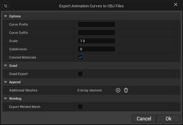
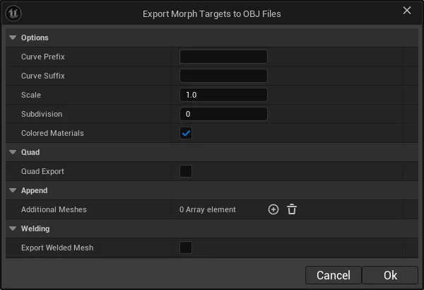
[MM-592] Implemented the ability to export Animation Curves (bulk) to OBJ Files (Poser and any weighted curve list)
[MM-593] Implemented the ability to export Morph Targets (bulk) to OBJ Files (Poser and any weighted curve list)
[MM-594] Implemented the ability to enable Connected Only for brushes which allows brushes to affect only connected triangles.
[MM-595] Fixed a bug with undo/redo which crashed Mesh Morpher when actions where triggered too fast.
[MM-596] Fixed a bug where bInvertMask option would be saved and transferred on tool change.
[MM-597] Fixed a bug where increasing/decreasing brush size with key shortcut wouldn't save and transfer the new brush size on tool change
Mesh Morpher 3.1.8 is Live! (10/25/2023)
[MM-588] Renamed Blend window to the correct name "Blend" instead of "Bake"
[MM-589] Implemented the ability to select and copy name of the selected Morph Target in Blend
[MM-590] Implemented the ability to select and copy name of the selected Morph Target in Bake
[MM-591] Fixed a bug with Morph Target list that appeared in certain cases when Auto was enabled and then disabled
Mesh Morpher 3.1.7 is Live! (10/24/2023)
[MM-582] Fixed a bug with Transaction(Undo/Redo) for Sculpt tools
[MM-586] Implemented the ability to temporarily subdivide the morph target in Sculpt tools. Use with caution as the sculpt performance decreases the more subdivision steps.
[MM-587] Improved performance of lattice deformer
Mesh Morpher 3.1.6 is Live! (10/22/2023)
[MM-579] Implemented Lattice Deformer Tool
[MM-580] Fixed a selection bug with Tools that prevented to display selection when navigating through tools
[MM-581] Fixed a selection bug with Tools that would always add full section selection vertices even though some vertices were removed by masking.
Mesh Morpher 3.1.5.1 is Live! (10/20/2023)
[MM-578] Fixed a bug in Sculpt tool when changing the tool would only select back the section selection if having section selection and additional selected masked vertices
Mesh Morpher 3.1.5 is Live! (10/20/2023)
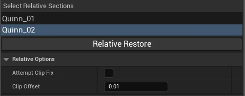
[MM-577] Implemented Relative Restore
Mesh Morpher 3.1.4 is Live! (10/19/2023)
[MM-557] Sculpt Tools now are listed as a side menu instead of a dropdown list.
[MM-558] Converted sculpt tools to C++
[MM-559] Implemented the ability to scale Modal Windows (In Edit->Settings.)
[MM-560] Moved Bone settings from Edit->Settings to Bone widget
[MM-561] Moved Control Points settings from Edit->Settings to Control Points widget
[MM-562] Moved Masking settings in Wrapper from Edit->Settings to Masking Widget
[MM-563] Implemented the ability to export selection and morph targets as welded/unwelded
[MM-564] Create from Mesh Files now preserves the settings
[MM-565] Export to OBJ now preserves the settings.
[MM-566] Implemented the ability to open a Current Pose from Poser in OBJ/FBX Importer
[MM-567] Implemented the ability to export a pose to OBJ file directly from Poser.
[MM-568] Added Tools menu to Poser
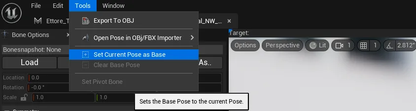
[MM-569] Implemented the ability to set or remove a Base Pose in Poser. A base pose is used when creating a corrective morph target which will contain the deltas between the Base Pose and the Current Pose.
[MM-570] Implemented the ability to open Base Pose from Poser to OBJ/FBX Importer
[MM-571] Copy Morph Target now preserve settings
[MM-572] Create From Mesh now preserve settings
[MM-573] Implemented confirmation message when overwriting bonesnapshots.
[MM-574] Transform Tool now supports Invert Mask
[MM-575] Added progress dialog to selection export
[MM-576] Implemented the ability to focus selected bone.
Mesh Morpher 3.1.3 is Live! (10/03/2023)
[MM-553] Implemented Progress Bar on Copy multiple Morph Targets
[MM-554] Implemented the ability to copy the name(s) of selected in Curve lists
[MM-555] Fixed a bug where sculpt tools would not correctly project morph targets to skeletal mesh in certain cases
[MM-556] Implemented the ability to enable PerSectionWeld
Mesh Morpher 3.1.2 is Live! (09/27/2023)
[MM-551] Implemented Rotation and Location grid snapping in all Viewports
[MM-552] Added bUsePrecompiled = true to build.cs files to prevent the plugin to be recompiled while using source builds and C++ projects
Mesh Morpher 3.1.1 is Live! (09/26/2023)
[MM-545] Implemented the ability to select delta vertices in Tools
[MM-546] Implemented the ability to set a static mesh as reference in Poser
[MM-547] Renamed Create from Pose menu entries to Poser
[MM-548] Fixed a bug with Transform tool where having the mask selection enabled and setting transform inputs or moving the gizmo would cause issues.
[MM-549] Moved the transform bone widget above the bone list
[MM-550] Added Buffer View Menu to all Mesh Morpher Viewports.
Mesh Morpher 3.1.0 is Live! (09/19/2023)
[MM-543] Improved Morph Target to Bonesnapshot algorithm
[MM-544] Improved Update Morph Target from Pose
Mesh Morpher 3.0.9 is Live! (09/18/2023)
[MM-541] Implemented the ability to update bone rotations when creating bonesnapshots from morph targets
[MM-542] Implemented the ability to use relative transforms when creating bonesnapshots from morph targets
Mesh Morpher 3.0.8 is Live! (09/17/2023)
[MM-539] Morph Target curves are now added to the skeleton instead of mesh
[MM-540] Fixed a bug where transform widget in Poser and Wrapper wouldn't process manual input for Location
Mesh Morpher 3.0.7 is Live! (09/16/2023)
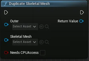
[MM-536] Implemented DuplicateSkeletalMesh at runtime
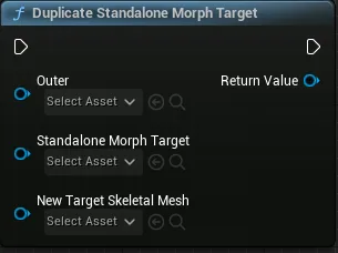
[MM-537] Implemented DuplicateStandaloneMorphTarget at runtime
[MM-538] Fixed a packaging issue with UE 5.3 (Windows)
Mesh Morpher 3.0.6 is Live! (09/14/2023)
[MM-534] Implemented the ability to enable/disable symmetry rotation
[MM-535] Implemented the ability to change symmetry axis
Mesh Morpher 3.0.5 is Live! (09/14/2023)
[MM-528] Improved Animation Curve list widget.
[MM-529] Implemented the ability to enable/disable Auto in Animation Curve/Morph Target list, which resets the weight to 0.
[MM-530] Animation Curves are now grabbed from the skeleton (and skeletal mesh in 5.3) instead of animation sequence.
[MM-531] Improved Bone Transform Widget in Poser and Wrapper.
[MM-532] Implemented Scale Lock in Bone Transform Widget in Poser and Wrapper
[MM-533] Improved and re-arranged Bone Widgets in Poser and Wrapper
Mesh Morpher 3.0.4 is Live! (09/12/2023)
[MM-524] Implemented bone symmetry in Poser and Wrapper.
[MM-525] Morph Target curves are properly created, renamed and removed in 5.3
[MM-526] Fixed a bug that could possibly crash Mesh Morpher when the versioning URL is not accessible
[MM-527] Improved Transform widget in Wrapper and Poser
Mesh Morpher 3.0.3 is Live! (09/09/2023)
[MM-522] Improved version update notification
[MM-523] Creating Morph Targets in UE 5.3 now explicitly creates a Curve for the Morph Target.
Mesh Morpher 3.0.2 is Live! (09/09/2023)
[MM-521] Load Bonesnapshot doesn`t modify bones that are also shared by a parent component (if any)
Mesh Morpher 3.0.1 is Live! (09/06/2023)
[MM-519] Implemented Subdivision in Create from Mesh Files
[MM-520] Implemented Match UV Iterations in Create from Mesh Files
Mesh Morpher 3.0.0 is Live! (08/30/2023)
[MM-500] Removed Sculpt Max Tool. Sculpt Tool now holds parameters for Max variant as well.
[MM-501] Smooth Tool now has a boolean that allows to preserve UV flow
[MM-502] Improved Flatten Tool performance with multi-threading
[MM-503] Improved Inflate Tool performance with multi-threading
[MM-504] Improved Move Tool performance with multi-threading
[MM-505] Improved Pinch Tool performance with multi-threading
[MM-506] Improved Plane Tool performance with multi-threading
[MM-507] Improved Sculpt Tool performance with multi-threading
[MM-508] Improved Smooth Tool performance with multi-threading
[MM-509] Improved Restore Tool performance with multi-threading
[MM-510] Improved Flatten Tool algorithm.
[MM-511] Improved Plane Tool algorithm.
[MM-512] Improved Sculpt Tool algorithm.
[MM-513] Improved Inflate Tool algorithm.
[MM-514] Removed Cotan, Mean Value and Legacy smooth types and they're been replaced by Preserve UV Flow and Delta smooth types
[MM-515] Implemented Subdivision in Copy Morph Target which allows to subdivide the source mesh. This most likely will provide better results when a subdivision level higher than 0 is used.
[MM-516] Changed default Smooth type to Preserve UV Flow
[MM-517] Fixed a bug in wrapper where setting a bonesnapshot wouldn't update the reference mesh
[MM-518] Improved Delta Projection algorithm in editor
Please remove the current Mesh Morpher files and replace them with the new ones.
Mesh Morpher 2.9.5 is Live! (08/26/2023)
Fixed a newly introduced bug with GetDynamicMeshDataPairs where the pairs were not correctly created between target and source
Mesh Morpher 2.9.4 is Live! (08/26/2023)
[MM-498] Improved control points behavior and how they function
[MM-499] Reorganized Wrapper Settings
Mesh Morpher 2.9.3 is Live! (08/23/2023)
[MM-495] Improved Control Points performance in Wrapper.
[MM-496] Control Points now can affect triangles facing the same direction as the control point
[MM-497] Wrapping can now be canceled.
Mesh Morpher 2.9.2 is Live! (08/22/2023)
[MM-484] Re-organized Wrapper settings structure
[MM-485] Wrapper can now be forced to attempt to preserve details
[MM-486] Creating Bonesnapshot for Morph Target now implements the ability to create automatically the Morph Target with deltas between the skeleton changes and the final form
[MM-487] Implemented the ability to update a Morph Target`s deltas with the current pose in Poser
[MM-488] Implemented Load Bonesnapshot widget
[MM-489] Implemented Save Bonesnapshot widget
[MM-490] Implemented the ability to create Reverse Morph Targets in Poser
[MM-491] Implemented the ability to select whether to load delta or absolute transforms from bonesnapshots
[MM-492] Implemented the ability to save bonesnapshots from a starting bone
[MM-493] Implemented the ability to removes bones in a bonesnaposhot from a bonesnapshot
[MM-494] Various other small fixes and UI changes
Mesh Morpher 2.9.1 is Live! (08/20/2023)
[MM-478] Implemented UV Matching in Copy Morph Targets
[MM-479] Creating from Mesh now has an advanced UV Matching functionality that allows multiple UV Matching iterations and smoothness
[MM-480] Removed Merge Morph Targets and it was replaced by Blend Morph Targets.
[MM-481] Wrapper no longer projects final result once more to the target mesh.
[MM-482] Wrapper now allows to bleed deltas from selection to nearby vertices, using Inverse Matching.
[MM-483] Fixed a bug that would crash the engine when changing skeletal meshes.
Mesh Morpher 2.9.0 is Live! (08/16/2023)
[MM-477] Improved speed of converting animation curves to morph targets.
Mesh Morpher 2.8.9 is Live! (08/11/2023)
[MM-473] Implemented the ability to Stitch a Morph Target back to the reference mesh
[MM-474] Improved UV Matching algorithm. Creating from Mesh files with UV matching disabled allows for inputs with different vertex count.
[MM-475] Implemented UV Matching in Create from Mesh Asset
[MM-476] Fixed a bug in UV Matching where if the morphed triangle count was lower than the base triangle count, the engine would crash.
Mesh Morpher 2.8.8 is Live! (08/06/2023)
[MM-470] Implemented the ability to match Base and Morphed files in Create From Mesh Files by UVs. This allows users to create Morph Targets from files with different vertex order if the UVs are intact in both files.
[MM-471] Implemented the ability to create a backup of skeletal mesh on bake.
[MM-472] Implemented the ability to select whether to bake Mesh Data on bake skeleton.
Mesh Morpher 2.8.7 is Live! (07/28/2023)
[MM-469] Fixed a newly introduced bug where the bonesnapshots wouldn't be correctly loaded in certain cases in animation blueprint
Mesh Morpher 2.8.6 is Live! (07/27/2023)
[MM-463] Fixed an issue with bonesnapshots where in Mesh Morpher the stored absolute transform wasn't used at all.
[MM-464] Bonesnapshots Deltas are now the bone transforms relative to their parents.
[MM-465] Add Support for UE 5.3 Preview 1
[MM-466] Implemented the ability to disable Post Process Animation Blueprints in Mesh Morpher by going to Edit->Settings
[MM-467] Implemented Morph Target Blender which allows to quickly select multiple values for Morph Targets and create a new one based on their blended results.
[MM-468] Runtime Nodes require activation when they are executed in Editor(PIE, Standalone). When packaged, the nodes don't require any activation. User have two new nodes: Is Activated and Activate available in blueprints.
Bonesnapshots format has been changed. Bonesnapshots created in previous versions are not working anymore and users have to recreate them.
Mesh Morpher 2.8.5 is Live! (07/02/2023)
[MM-460] Improved the side menu in Poser.
[MM-461] Moved authentication to cloud.
[MM-462] Improved Mac version.
Mesh Morpher 2.8.4 is Live! (06/22/2023)
[MM-458] Implemented the ability to match material IDs on copy morph target. This should provide better results when target and source meshes share same material layers count and order.
[MM-459] Checking for updates is now done only once per session.
Mesh Morpher 2.8.3 is Live! (06/21/2023)
[MM-455] Implemented Main Iterations in Wrapper which adds extra control on iterations. More iterations mean better quality. A Main Iteration of 1 is the default.
[MM-456] Fixed a bug in Wrapper where selecting a section in Target mesh would not correctly apply the resulted wrapping.
[MM-457] Runtime module refactoring which cleans and optimizes the code
This update on the backend is big. Don't hesitate to get in touch if you face any issues.
Mesh Morpher 2.8.2 is Live! (06/17/2023)
[MM-452] Implemented the ability to lock viewport camera in wrapper. This allows to automatically replicate viewport camera transformation from focused viewport to the other
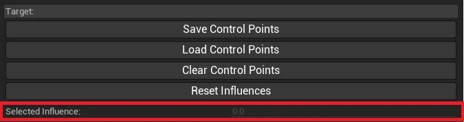
[MM-453] Implemented the ability to select different Control Point influence values in the same wrapping operation.
[MM-454] Implemented the ability to select a control point and modify its influence radius
Mesh Morpher 2.8.1 is Live! (06/12/2023)
[MM-451] Fixed a bug with Merging Morph Targets where the resulted Morph Target wouldn't be properly created
Mesh Morpher 2.8.0 is Live! (05/29/2023)
[MM-450] Fixed a bug where on Lost Focus of viewport in wrapper will cause symmetric control points to remain enabled even while shift key was released
Mesh Morpher 2.7.9 is Live! (05/21/2023)
[MM-444] Fixed an issue where baking skeleton or morph target in some cases the engine would change the vertex order. On bake now we reload the baked skeletal mesh.
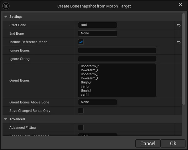
[MM-445] Creating a Bonesnapshot from Morph Target now opens a settings dialog which allows to configure how the bonesnapshot will be created.
[MM-446] Improved the layout of all modal dialogs
[MM-447] Bone Transform Widgets in Poser and Wrapper now work in local bone space.
[MM-448] Bake Skeleton in Poser now offers a set of option which allow to pick whether users want to bake to mesh skeleton reference, skeleton asset and DNA asset
[MM-449] Recompute Normals now has an improved output for selected meshes with different LOD count(eg. Meta Humans) for LOD indexes higher than 0
Mesh Morpher 2.7.8 is Live! (05/16/2023)
[MM-443] Implemented the ability to save only changed bones in bonesnapshots
Mesh Morpher 2.7.7 is Live! (05/16/2023)
[MM-442] Fixed a bug where transitioning through states between 0 and 1 using Anim Node Load Bonesnapshots wouldn't work perfectly
Mesh Morpher 2.7.6 is Live! (05/15/2023)
[MM-436] Fixed DNA export to file
[MM-437] Implemented Load Bonesnapshot animnode
[MM-438] Bonesnapshot now save both local deltas and world transforms
[MM-439] Implemented the ability to set a bonesnapshot as a pose in toolkit window
[MM-440] Implemented the ability to save bonesnapshots as.. in Poser
[MM-441] Implemented the ability to merge bonesnapshots in Poser
Bonesnapshots created prior to 2.7.6 need to be recreated as they will not function anymore
Mesh Morpher 2.7.5 is Live! (05/06/2023)
[MM-434] Default value for Smooth Iterations in Create from Mesh Files has been changed to 0
[MM-435] Improved authentication in Mesh Morpher. Now when there's no Mesh Morpher window open, there's no request for authentication.
Mesh Morpher 2.7.4 is Live! (05/02/2023)
[MM-433] Bone trees selection gets updated when bones are selected from Bone Proxies in viewports
Mesh Morpher 2.7.3 is Live! (04/27/2023)
[MM-430] Fixed viewport flickering (if it still flickers please send an email at support@meshmorpher.com)
[MM-431] Duplicate Morph Targets now pre-fills the morph name to the existing one
[MM-432] Fixed a bug with re-applying morph target to LODs.
Mesh Morpher 2.7.2 is Live! (04/14/2023)
[MM-428] Implemented the ability to select an Animation Blueprint in Poser, enabling Arkit and everything related to animation in Mesh Morpher
[MM-429] Selected Bone Transform Widget in Poser now follows animation bone position.
Mesh Morpher 2.7.1 is Live! (04/12/2023)
[MM-425] Restore Tool can now restore by side: Right, Left, Up, Down, Front, Back
[MM-426] Masking can now select by side: Right, Left, Up, Down, Front, Back
[MM-427] Fixed a bug where adding a new morph target with an existing name wouldn't overwrite the deltas.
Mesh Morpher 2.7.0 is Live! (04/06/2023)
[MM-223] All binaries files are now digitally signed
[MM-224] Implemented auto-updater in Mesh Morpher. Upcoming Mesh Morpher version can be fetched within the engine.
Mesh Morpher 2.6.9 is Live! (04/01/2023)
[MM-422] Fixed a bug where grabbing deltas from import data wouldn't work correctly in certain cases. Instead, we now grab deltas only from UMorphTarget objects.
Mesh Morpher 2.6.8 is Live! (03/31/2023)
[MM-418] Bonesnapshots have been changed. The bone transformation storage is completely changed and requires users to recreate them.
[MM-419] Renaming a Morph Target now pre-fills the text block with current Morph Target name
[MM-420] Wrapper control points index indicator are not render anymore if they're outside of viewport frustum
[MM-421] Fixed a bug where creating the bones gizmos would crash the engine
Mesh Morpher 2.6.7 is Live! (03/30/2023)
[MM-417] Bone Tree fits better in Poser side panel
Mesh Morpher 2.6.6 is Live! (03/28/2023)
[MM-416] Improved authentication in Mesh Morpher. This resets the current authentication token stored locally.
Mesh Morpher 2.6.5 is Live! (03/26/2023)
[MM-415] Implemented Recompute Normals
Mesh Morpher 2.6.4 is Live! (03/24/2023)
[MM-414] Fixed a bug where selecting a Reference Skeletal Mesh wouldn't display its Morph Targets
Mesh Morpher 2.6.3 is Live! (03/23/2023)
[MM-412] Implemented the ability to enable Animation Curves in Poser
[MM-413] Implemented the ability to Create Morph Targets from Animation Curves Selection
Mesh Morpher 2.6.2 is Live! (03/21/2023)
[MM-410] Added Symmetric Control Points
[MM-411] Updated default Wrapping settings
Mesh Morpher 2.6.1 is Live! (03/21/2023)
[MM-409] Improved the smoothing for non-rigid wrapping
Mesh Morpher 2.6.0 is Live! (03/20/2023)
[MM-407] Implemented the ability to chose fitting algorithm for control points.
[MM-408] Wrapping progress for Control Points now display the control point index instead of the nearest vertex index in the mesh
Mesh Morpher 2.5.9 is Live! (03/20/2023)
[MM-406] Vertices in Control Points influence radius can have multiple correspondence vertices
Mesh Morpher 2.5.8 is Live! (03/20/2023)
[MM-399] Control Points in Wrapper now just hint the non-rigid algorithm about their correspondence vertices in their influences radius instead of rigidly fitting.
[MM-400] Greatly improved the non-rigid algorithm in Wrapper
[MM-401] Implemented the ability to save/load control points.
[MM-402] Implemented the ability to clear control points.
[MM-403] Control Points now display their index in Wrapper viewport
[MM-404] Subdivision steps in Wrapper now subdivides the source mesh for the amount of steps at the beginning instead of going through each step with the non-rigid fitting.
[MM-405] Removed bFitToTarget from wrapper as this causes issues with non-manifold meshes
Mesh Morpher 2.5.7 is Live! (03/12/2023)
[MM-397] Added extra validations when writing to DNA asset.
[MM-398] Implemented the ability to turn off DNA asset update when baking skeleton or morph target. (Edit->Settings)
Mesh Morpher 2.5.6 is Live! (03/12/2023)
[MM-394] Applying Deltas from Welded(sculpted version) to Skeletal Mesh now matches material IDs, providing higher quality projection
[MM-395] Creating from Mesh Files now offers the ability to match material IDs
[MM-396] Creating from Mesh now offers the ability to match material IDs
Mesh Morpher 2.5.5 is Live! (03/02/2023)
[MM-393] Fixed and improved Regenerate Import Data and Model
Mesh Morpher 2.5.4 is Live! (02/26/2023) [Only on MeshMorpher.com]
[MM-388] Bonesnapshots are now saved with bone names included
[MM-389] Implemented the ability to create bonesnapshot assets using blueprints in editor (CreateBoneSnapshotAsset)
[MM-390] Implemented the ability in Poser to load bonesnapshots that are not skeleton compatible. Common bones with same names will be transferred
[MM-391] Baking Skeleton and Baking Morph Targets now write the joint and mesh data to DNA asset for Meta Humans
[MM-392] Implemented the ability to export the DNA asset(Meta Humans) to .dna file (experimental)
Mesh Morpher 2.5.3 is Live! (02/22/2023) [Only on MeshMorpher.com]
[MM-385] Create From FBX Files now uses the skeletal mesh from toolkit viewport(pose or master pose component applied)
[MM-386] Export Mesh to OBJ now uses the skeletal mesh from toolkit viewport(pose or master pose component applied)
[MM-387] Export Morph Target to OBJ now uses the skeletal mesh from toolkit viewport(pose or master pose component applied)
Mesh Morpher 2.5.2 is Live! (02/19/2023) [Only on MeshMorpher.com]
[MM-381] Fixed a bug with transform tool where closing and reopening the tool would wrongfully reposition the gizmo
[MM-382] Baking Bonesnapshots now notify all existing viewports that the mesh was changed
[MM-383] Baking Bonesnapshots now reinitializes render data and clears out much better.
[MM-384] Ok button in Poser has been renamed to Create Morph Target
Mesh Morpher 2.5.1 is Live! (02/16/2023) [Only on MeshMorpher.com]
[MM-380] Fixed a bug with Copy where the Morph Target wouldn't be properly projected on the target LODs > 0 and disabling UV Projection wouldn't work properly.
Mesh Morpher 2.5.0 is Live! (02/16/2023) [Only on MeshMorpher.com]
[MM-379] Implemented the ability to fit skeletons to Morph Targets
Mesh Morpher 2.4.9 is Live! (02/15/2023) [Only on MeshMorpher.com]
[MM-376] Implemented the ability to bake skeletons
[MM-377] Implemented the ability to draw simplified bones in Wrapper and Poser
[MM-378] Implemented the ability to scale bone indicators to bones in Wrapper and Poser
Mesh Morpher 2.4.8 is Live! (02/05/2023)
[MM-375] Fixed a bug with creating Morph Targets at runtime
Mesh Morpher 2.4.7 is Live! (01/30/2023)
[MM-372] Fixed a bug with Pinch Tool
[MM-373] Moved unnecessary components and libraries from Runtime module to Core. Only necessary stuff will now be packaged.
[MM-374] Fixed baking once and for all. (Special thanks to @kostenickj for helping out with this)
Mesh Morpher 2.4.6 is Live! (01/25/2023)
[MM-367] Fixed a bug with Mesh Morpher Debug Skeletal Mesh where assigning a different mesh after a mesh was previously assigned, would preserve the materials from the old mesh.
[MM-368] Fixed a bug where on save, Source bone snapshot was selecting the target mesh as skeletal mesh in Wrapper
[MM-369] Fixed a bug with Bone Snapshot assets where the Skeletal Mesh Property wouldn't preserve its value
[MM-370] Fixed a bug with Standalone Mask Selection assets where the Skeletal Mesh Property wouldn't preserve its value
[MM-371] Fixed a bug in Mesh Morpher Mesh Component where the Scene Proxy wasn't flushing rendering commands when the topology was changed potentially crashing
Mesh Morpher 2.4.5 is Live! (01/23/2023)
[MM-366] Fixed a possible bug with baking where in certain cases where import data is not consistent, the mesh becomes scrambled.
Mesh Morpher 2.4.4 is Live! (01/18/2023)
[MM-365] Fixed a bug in Mesh Morpher Mesh Component Scene Proxy where updating the mesh data could result in a crash
Mesh Morpher 2.4.3 is Live! (01/15/2023)
[MM-364] Bone Snapshot menu has been re-added to Poser. It went MIA during UI refactoring
Mesh Morpher 2.4.2 is Live! (01/11/2023)
[MM-361] Fixed a bug with baking where Mesh Morpher would fail to offset the existing Morph Targets
[MM-362] Baking performance has been greatly improved.
[MM-363] Fixed a bug with Symmetric Brush for Tools where the Symmetric Brush would be incorrectly positioned when Only Facing Camera was disabled
Mesh Morpher 2.4.1 is Live! (01/10/2023)
[MM-354] Windows with Viewports and Morph Targets Lists have been replaced with dockable tabs
[MM-355] Implemented an Entitlement Check which attempts to inform users if they don't own the product. Mesh Morpher as any other code plugin on the UE Marketplace is licensed per seat.
[MM-356] Implemented the ability to regenerate import data which is useful for some marketplace assets.
[MM-357] Code refactor for Editor and Core Modules
[MM-358] Fixed a bug where closing windows(now tabs) with viewports in 5.1 would result in a crash(sometimes)
[MM-359] Various optimizations to UI across the plugin
[MM-360] Fixed a bug with Fit to Target in Wrapper when sometimes could result in a crash. Fit to Target can fail fitting but won't crash.
Mesh Morpher 2.4.0 is Live! (12/30/2022)
[MM-351] Copy Morph Targets now uses the source skeletal mesh with pose applied (if any)
[MM-352] Reference Mesh Master Pose functionality has been simplified. Instead of two booleans now it uses an enum to set the correct Master pose.
[MM-353] Fixed a bug where changing a bone transformation using the text widgets and then moving the transform gizmo would result in a crash in Wrapper and Poser
Mesh Morpher 2.3.9 is Live! (12/26/2022)
[MM-348] Fixed a bug where on opening a mask selection asset, the selection will always be appended.
[MM-350] Mask selection mesh is drawn at an offset distance of Normal * 0.1 to make sure is always on top
Mesh Morpher 2.3.8 is Live! (12/26/2022)
[MM-349] Fixed a bug with Reference Mesh in Poser where the mesh would attempt to inherit vertices from the Pose Mesh Component
Mesh Morpher 2.3.7 is Live! (12/24/2022)
[MM-334] Fixed control points in Wrapper
[MM-335] Optimized wrapper
[MM-336] Implemented Masking in Wrapper.
[MM-337] Tools are using now internal smooth enum
[MM-338] Implemented Legacy smooth option which allows users to use the old smoothing algorithm(if they want to)
[MM-339] Implemented the ability to enable Morph Targets in poser.
[MM-340] On bonesnapshot save, users are now notified when the save is complete.
[MM-341] Implemented the ability to select a Reference Mesh in poser.
[MM-342] Implemented the ability to Fit Scale Source to Target in Wrapper
[MM-343] Implemented the ability to Hide Preview and Reference Meshes in Wrapper
[MM-344] IsDynamicMeshIdentical doesn't check for identical normals anymore.
[MM-345] Renamed Select Only Facing Camera to Only Facing Camera in Tools.
[MM-346] Removed Hit Back Faces from Tools, functionality is replaced by Only Facing Camera.
[MM-347] Now Bones in Poser and Wrapper are reset on Bonesnapshot load
Mesh Morpher 2.3.6 is Live! (12/20/2022)
[MM-324] Fixed a bug with Add New Morph Target where if the selected name is already in use, the overwrite happens without unloading the Morph Target if it is already loaded
[MM-325] Fixed a bug with Duplicate Morph Target where if the selected name is already in use, the overwrite happens without unloading the Morph Target if it is already loaded
[MM-326] Fixed a bug with Merging Target where if the selected name is already in use, the overwrite happens without unloading the Morph Target if it is already loaded
[MM-327] Merging doesn't allow anymore to pick a Destination name that is part of the selection
[MM-328] Fixed a bug with UMeshMorpherDebugSkelMesh where the bone caching wasn't working as intended
[MM-329] Fixed a bug in wrapper and poser viewport where clicking bones wouldn't work as intended due to cursor hiding
[MM-330] Fixed bonesnapshot bugs in wrapper and poser where the bonesnapshot wouldn't be correctly saved or loaded
[MM-331] Fixed a packaging issue for 5.1 due to fbxsdk missing files
[MM-332] Added Docs and Support menu option under Help dropdown menu
[MM-333] Threshold and Normal Incompatibility Threshold have been removed from the wrapper as they were not used.
Mesh Morpher 2.3.5 is Live! (12/09/2022)
[MM-317] Fixed a bug where Cancel on saving bone snapshot bug would crash the engine
[MM-318] Fixed a bug where the material for reference meshes in wrapper weren't properly assigned
[MM-319] Fixed a bug where undoing bone actions would sometimes fail in the wrapper and poser
[MM-320] Selecting an animation in the wrapper and poser still allows you to move bones around thus enabling further pose customization
[MM-321] Removed bDisablePostProcessBlueprint. The Debug Skeletal Mesh Component has been redone.
Mesh Morpher 2.3.4 is Live! (12/06/2022)
[MM-323] Fixed a baking bug where the Normals wouldn't be properly stored
Mesh Morpher 2.3.3 is Live! (12/06/2022)
[MM-322] Cleaned the wrapper
Mesh Morpher 2.3.2 is Live! (11/21/2022)
[MM-312] Implemented the ability to enable/disable Post Process Animation blueprint
[MM-313] Added some extra validation for the Pose frame slider
[MM-314] Separated Wrapper from Create from Mesh to its own window.
[MM-315] Fixed a possible bug where browsing corrupted assets would crash the engine. Now Mesh Morpher attempts to filter them out.
[MM-316] Create From Mesh window doesn't automatically close after the Morph Target was created, allowing users to select another mesh directly.
Mesh Morpher 2.3.1 is Live! (11/11/2022)
[MM-309] Improved baking(Set Weight) Standalone Morph Target at runtime
[MM-310] Implemented profiling for runtime functionality
[MM-311] Fixed a bug in Mesh Morpher Mesh Component where changing the mesh would crash the editor
Mesh Morpher 2.3.0 is Live! (11/04/2022)
[MM-306] Implemented the ability to Create Standalone Morph Targets from FBX/OBJ Files at runtime
[MM-307] Implemented the ability to Create Morph Targets from FBX/OBJ Files at runtime
[MM-308] Implemented the ability to Export Skeletal Mesh Render Data (reflects already baked standalone morph targets) to OBJ Files at runtime. Welded and non-welded support
Mesh Morpher 2.2.9 is Live! (11/02/2022)
[MM-305] Fixed a bug with Baking(Set Weight) of standalone morph targets in packaged builds where it would crash the game.
Mesh Morpher 2.2.8 is Live! (10/31/2022)
[MM-301] Implemented the option to project at runtime Standalone Morph Targets to another mesh Standalone Morph Targets
[MM-302] Implemented the option to project at runtime Standalone Morph Targets to another mesh Morph Targets
[MM-303] Implemented various utility nodes for Standalone Morph Targets assets.
[MM-304] Implemented the ability to bake Standalone Morph Targets on the skeletal mesh at runtime
There is a bug with baking Standalone Morph Targets at runtime in packaged builds but the fix has been submitted already to Epic and it will be available in 2.2.9 version.
Mesh Morpher 2.2.7 is Live! (10/30/2022)
[MM-299] Implemented Smooth Types in Mesh Morpher core functionality. There are 3 smooth types: uniform, mean value, cotan
[MM-300] Improved performance and quality of smoothing in core functionality.
You'll see that the default smoothing values have changed across Mesh Morpher(Copy, Create From Mesh File, Wrapper etc.) because the entire algorithm has changed and the impact is different. However, this change doesn't affect previously created Morph Targets.
Mesh Morpher 2.2.6 is Live! (10/28/2022)
[MM-297] Merge Morph Targets now can use 3 types of merging: Append, Magnitude and Mean Average
[MM-298] Baking has been further improved.
Mesh Morpher 2.2.5 is Live! (10/26/2022)
[MM-296] Fixed a bug where changing the Skeletal Mesh to another one after any modification was made would result in a crash.
Mesh Morpher 2.2.4 is Live! (10/22/2022)
[MM-295] Pose Mesh Component and Reference Mesh Component in Toolkit now have disabled post process and control rig
Mesh Morpher 2.2.3 is Live! (10/19/2022)
[MM-287] Discontinued Meta Morph assets
[MM-288] Importing from FBX/OBJ now has default Forward axis to Y and T0 pose enabled. This is implemented by default to match Unreal Engine's behavior
[MM-289] Optimized wrapping to use vertex pairs per material. This could slightly increase the quality of the results when copying, wrapping etc.
[MM-290] Create from Pose now allows users to manage bones individually while in Mesh Morpher.
[MM-291] Mesh Morpher can be compiled by users to support UE 5.1 P1/2
[MM-292] Fixed a bug with FBX importer where it would crash from time to time
[MM-293] Bone Editor in Wrapper and Poser doesn't duplicate the skeletal meshes anymore hence the performance is a little bit improved
[MM-294] Added Create from Mesh and From Pose to the Toolbar
Mesh Morpher 2.2.2 is Live! (10/04/2022)
[MM-284] Fixed a bug with Bone Snapshots where the skeletal mesh wouldn't get stored and would result in an engine crash when browsing the assets.
[MM-285] Windows with Viewports (Wrapper, Create From Mesh Files etc) now have persistent window size.
[MM-286] Implemented Section Selection in the Wrapper.
Mesh Morpher 2.2.1 is Live! (09/22/2022)
[MM-233] Implemented Bone Snapshots in the Wrapper, allowing users to save the current Bones Transformation to an asset, and load it when needed
[MM-283] Implemented Source Pose and Frame for the wrapper, allowing users to set an animation sequence frame bone transformations to the Source Mesh
Mesh Morpher 2.2.0 is Live! (09/20/2022)
[MM-274] Improved bone rendering and interaction in the wrapper
[MM-275] Improved control point rendering and interaction in the wrapper
[MM-276] The wrapper now automatically attempts to rigid fit the target to source. Scaling is optional
[MM-277] Improved the performance speed of control points processing
[MM-278] The wrapper now centers target and source, as well as vertices affected by control points and their correspondents
[MM-279] Added GUI settings for the Wrapper in the Mesh Morpher's Settings window
[MM-280] Fixed a bug with undo/redo bone transforms in the wrapper. Now each bone has its own transform gizmo
[MM-281] Fixed several possible crashes when undo/redo transform bones in the wrapper
[MM-282] Fixed a bug where control points were displaying wrong influence radius
Mesh Morpher 2.1.9 is Live! (09/20/2022)
[MM-272] Implemented bone alignment for Wrapper
Mesh Morpher 2.1.8 is Live! (09/16/2022)
[MM-260] Fixed a bug where renaming a morph target to a previously removed morph target would result in a crash
[MM-261] Removed the option in baking where you could select to either remove or not the baked morph target. All baked morph targets are automatically removed.
[MM-262] Cleaned the Toolkit code a little bit
[MM-263] Projecting Morph Targets on an invalid LOD doesn't crash the engine anymore. Event is logged in Output log.
[MM-264] Implemented bOnCompleteRigidFitToOriginalMesh in Wrapper Settings which attempts to match the proportions and rotation of the resulted morph target to the original target mesh.
[MM-265] Implemented the ability to set a source from from file(FBX/OBJ) when using the wrapper.
[MM-266] Implemented the ability to manually change transform of the source mesh to manually match the target when using the wrapper
[MM-267] Implemented Control Points when using the Wrapper.
[MM-268] Wrapper automatically uses welded meshes for both target and source.
[MM-269] Rigid and Non-Rigid Settings are now separated when using Wrapper.
[MM-270] Cleaned and optimized the Wrapper
[MM-271] Fixed a bug in Transform Tool where Rotation Y axis would mistakenly be bound to Scale Y
Mesh Morpher 2.1.7 is Live! (09/01/2022)
[MM-257] Fixed a bug where smooth type combo box was not visible
[MM-258] Fixed a bug where the FBX Importer wouldn't import all mesh sections
[MM-259] Improved the Wrapper. We now have two types of fitting, rigid and non-rigid. Rigid attempts to align, rotate and scale(optional) the meshes to fit them as much as possible before non-rigid to make it easier on the algorithm. Non-rigid is using an enhanced ICP algorithm which attempts to fit the meshes by wrapping the target mesh around the source mesh.
The wrapper algorithm changed drastically, we now have plenty of options to optimize the wrapping process. We've reached a point where I believe the wrapping works as intended. Next step is to add the possibility to set control points to help the algorithm in certain areas.
Mesh Morpher's Wrapper is still in its early stages, very experimental but I'm heavily invested into implementing it.
Mesh Morpher 2.1.6 is Live! (08/25/2022)
[MM-256] Improved Create Morph Target From Mesh. This functionality is originally intended to work with Meta Human heads. With this version it allows the creation of Morph Targets from all kind of meshes.
This is still very experimental and work in progress. The best results come from meshes that share the skeleton and proportions and manifold.
Mesh Morpher 2.1.5 is Live! (08/21/2022)
[MM-253] Improved performance and accuracy of Morph Target projection on meshes. We're slowly preparing the grounds for the Wrapper functionality.
[MM-254] Improved ROI return performance in UMeshMorpherMeshComponent. Now it has better distribution across all threads.
[MM-255] Creating Morph Target from Meta Morphs (current mesh) has been implemented. It uses as a target mesh the current mesh with pose (if any)
Mesh Morpher 2.1.4 is Live! (08/18/2022)
[MM-240] Implemented T0 pose on FBX Import
[MM-241] Implemented the ability to set an offset location on FBX/OBJ import
[MM-242] Increased the accuracy of pose frame slider
[MM-243] Implemented a new SpinBox near the pose frame slider which allows to jump to certain frames and view the current frame position.
[MM-244] Section List in Tools is now using a fixed size with a scrollbar
[MM-245] Implemented Select All Sections in Tools
[MM-246] Implemented Export Morph Target As OBJ
[MM-247] Welding Settings are now centralized in Settings under Internal Welding Settings category. This allows for more consistency between Exported Meshes as OBJ(welded), Exported Morph Targets as OBJ(welded) and Mesh Morpher's internal mesh(welded)
[MM-248] Create Morph Target from Mesh Files is now using as a target mesh the existing mesh with pose applied(if any)
[MM-249] Removed Legacy OBJ Importer. Legacy OBJ Importer was only used for OBJ quad meshes. FBX/OBJ Importer now supports triangle/quad meshes with polygons of 3 or 4 elements. This change also fixes an existing visual rendering bug with quad meshes.
[MM-250] Mask Selection triangles are sorted now on Export Mask Selection to OBJ. This allows for more consistent exports.
[MM-251] Fixed a bug where if the sections materials are invalid then the mesh would be invisible when a Morph Target is open
[MM-252] Fixed a bug with Mesh Materials in Custom Scene Proxy where having invalid Materials on the skeletal mesh would sometimes cause a crash
Mesh Morpher 2.1.3 is Live! (08/16/2022)
This long overdue update is about improving performance and stability in Mesh Morpher core functionality.
I improved Scene Proxy performance and stability, allowing Mesh Morpher to send to the GPU only changes that were made instead of the whole mesh/selection data.
I also Improved Mesh Morpher's Mesh Component stability and performance by taking advantage of all CPU power/threads whenever possible.
Mesh Operations are now more performant due to better distribution across all available threads.
A lot of core functionalities were re-written to achieve this performance/stability improvement. If you find a bug, don't hesitate to let me know.
Mesh Morpher 2.1.2 is Live! (08/11/2022)
[MM-238] Fixed a bug in Baking where only the last selected Morph Target would be baked.
[MM-239] Camera Location, Rotation, Speed, Speed Scalar and FOV are now saved when users close Mesh Morpher window. This allows to preserve viewport camera settings.
[MM-240] Changing Pose asset or frame now automatically saves and close current selected Morph Target. The process is heavy and reopening the Morph Target everytime the pose frame is changed will halt Mesh Morpher for a long time.
Mesh Morpher 2.1.1 is Live! (07/30/2022)
[MM-231] Implemented the ability to customize Brush Sphere Indicator Alpha and Color in Settings
[MM-232] Implemented the ability to Display Material Slot Names instead of IDs in Tools
[MM-234] Renamed Mask Behaviour to Mask Visibility
[MM-235] Disable Mask Visibility when painting Mask Selection is enabled
[MM-236] Disable Mask Painting when Enabling Mask Visibility
[MM-237] Implemented the ability to export Material Slot Names instead of IDs on OBJ Export
Mesh Morpher 2.1.0 is Live! (07/24/2022)
[MM-229] Implemented the ability to hide Masked/Unmasked Vertices
[MM-230] Re-implemented Brush Sphere. It can be Enabled/Disabled in Edit->Settings
Mesh Morpher 2.0.9 is Live! (07/16/2022)
[MM-226] Implemented the ability to set Master Pose for Reference Skeletal Mesh
[MM-227] Pose assets now check compatibility between the skeleton and the animation asset thus allowing to select retargeted animations.
Mesh Morpher 2.0.8 is Live! (07/14/2022)
[MM-225] Implemented the ability to enable Morph Targets on Reference Skeletal Mesh
Mesh Morpher 2.0.7 is Live! (06/07/2022)
[MM-224] Fixed a bug where Smooth Tool didn't work correctly with Symmetry enabled
Mesh Morpher 2.0.6 is Live! (06/06/2022)
[MM-222] Fixed a bug where GetMaxGroupID() in UMeshMorpherMeshComponent was not displaying the correct sections count
[MM-223] OBJ and FBX importing now both use the FBX module in Unreal Engine. In Mesh Morpher now you can see one option, Create From Mesh Files which allows users to select both FBX and OBJ file formats. OBJ quad meshes behind the scenes are still processed by the old OBJ importer
Mesh Morpher 2.0.5 is Live! (06/02/2022) This version is available for UE 5.0.0 and higher.
[MM-220] Enhanced OBJ export functionality. Implemented the ability to append additional skeletal meshes to OBJ output allowing users to attach bodies to heads and so on. See notes.
[MM-221] Fixed a bug where changing the selected skeletal mesh while a dialog box was open wouldn't close the dialog box.
Notes: There are various options available now for OBJ export functionality, allowing users to weld exported mesh based on the given parameters or group additional meshes into separate Objects.These enhancements aim to ease up and simplify workflows.
Mesh Morpher 2.0.4 is Live! (05/28/2022) This version is available for UE 5.0.0 and higher.
[MM-215] Tools Material Mode selection is now saved and persistent
[MM-217] Fixed a bug in Create Morph Target from FBX Files widget when changing the Coordinate System or any of the Axis wouldn't show up the progress bar
[MM-218] Switched Versioning URL to new host. If users don't update to the latest version 2.0.4 they will not receive any further notifications about new versions.
Mesh Morpher 2.0.3 is Live! (05/09/2022) This version is available for UE 5.0.0 and higher.
[MM-211] Implemented the ability to select boundary vertices
[MM-212] Implemented the possibility to create Morph Targets from FBX files. See notes.
[MM-213] Cleared files from unnecessary includes.
[MM-214] Fixed a bug where OBJ importer wouldn't process quad meshes correctly
[MM-216] Implemented RebuildTangentBasis in baking Morph Targets to Skeletal mesh. Hopefully this will generate more consistent baking results.
Note: Creating Morph Targets from FBX files has been implemented to remove the need to import the FBX files in the engine first, which is causing vertices count/order inconsistencies by getting the meshes optimized by the Engine.
Mesh Morpher is only attempting to get the highest vertex count LOD(LOD0) when importing FBX files.
This has been tested with FBX files exported from UE, Maya and Blender.
This functionality is still experimental so please don't hesitate to report back with issues and suggestions.
Mesh Morpher 2.0.2 is Live! (04/15/2022) This version is available for UE 5.0.0 and higher.
[MM-207] Removed UStandaloneMorphTarget. UMetaMorph will take its place
[MM-208] Removed the ability to bake morph targets at runtime. This was an experimental feature and it failed to perform in UE5. As soon as I find a replacement I will implement it
[MM-209] Fixed a bug where on baking morph targets the normals would be broken when Virtual Shadow Mapping is selected.
Mesh Morpher 2.0.1 is Live! (04/09/2022) This version is available for UE 5.0.0 and higher.
[MM-176] Transform Gizmo in Transform Tool now allows Scaling
[MM-177] Convert float to double precision. This allows for higher quality Morph Targets when working with Mesh Morpher. However, UE's deltas are still floats.
[MM-178] Indicator now is drawn in Mesh Component Scene Proxy
[MM-182] Convert Tools to UMG Widgets
[MM-185] Fixed a bug in UMeshMorpherToolHelper::GetNormalizedLength
[MM-186] Implemented the ability to get the bounds of mask selection in UMeshMorpherMeshComponent
Mesh Morpher allows users to change the camera FOV in the preview viewport.
Navigate to the camera menu in the viewport and set the slider to the desired value.
Classic › Editor › UI
Focus Camera
Mesh Morpher allows users to focus the camera while pointing at the Skeletal Mesh to focus the camera on that specific point.
Navigate to Edit top dropdown menu and click Focus Camera.
Keyboard shortcut: F
Use Mouse Wheel to adjust the Focusing distance.
Classic › Editor › UI
Ruler
Ruler allows us to measure and Track MetaHuman Deformations with Ruler. We can track how Morph Targets, Animations, Animations Curves affect our selected Points of Interest so we can better underst...
Ruler allows us to measure and Track MetaHuman Deformations with Ruler. We can track how Morph Targets, Animations, Animations Curves affect our selected Points of Interest so we can better understand what we can do to fine-tune our skeletal meshes.
Left Click to add points. Right Click on points to remove them.
There are several ways you can open a Skeletal Mesh in Mesh Morpher.
Use the asset picker in Mesh Morpher's toolbar.
Select the Skeletal Mesh in Content Browser and click on Mesh Morpher icon.
Select the Skeletal Mesh in Content Browser, right click and select Open with Mesh Morpher.
Classic › Editor › Basic Operations
Save
Saves the changes to the Skeletal Mesh making them persistent.
Save button is accessible through:
Toolbar
Navigating to File top dropdown menu and clicking save
Keyboard shortcut: Ctrl + S
The button is greyed out when there's nothing recorded to save.
Saving is irreversible.
Classic › Editor › Basic Operations
Open Morph Target
Mesh Morpher allows users to load and sculpt existing Morph Targets in-engine.
There are three ways to load a Morph Target:
Double-click on the Morph Target you want to load in Morph Targets list.
Right-click on the Morph Target you want to load in Morph Targets list and select Open Morph Target.
Navigating to Edit top dropdown menu and clicking Open Morph Target
Keyboard shortcut: Ctrl + O
Classic › Editor › Basic Operations
Close Morph Target
Mesh Morpher allows users to unload Morph Targets that have been previously loaded.
There are two ways to unload a loaded Morph Target:
By right-clicking on the Morph Targets list and select Close Morph Target.
Navigating to Edit top dropdown menu and clicking Close Morph Target.
If there are any changes to the Morph Target, Mesh Morpher will attempt to save them.
Keyboard shortcut: Ctrl + D
The button is greyed if no Morph Target is loaded.
Classic › Editor › Basic Operations
Add New
Mesh Morpher allows users to create and sculpt new Morph Targets in-engine without the need of any other DCC software.
There are three ways to create new Morph Targets:
By clicking Add New in Mesh Morpher's toolbar
By right-clicking on the Morph Targets list and select Add new
Navigating to Edit top dropdown menu and clicking Add new
Once the Add New button is pressed, a dialog box will open, asking for a name for the new Morph Target.
If the selected Morph Target name is already in use, a new dialog box will pop asking whether to overwrite or change the name. Pressing Yes will clear and overwrite the existing Morph Target.
Keyboard shortcut: Ctrl + A
Classic › Editor › Basic Operations
Delete
Mesh Morpher allows users to delete Morph Targets in-engine without the need of any other DCC software.
You can delete a single Morph Target or multiple Morph Targets by using Ctrl+Click or Shift+Click to select additional Morph Targets in the Morph Targets list.
There are three ways to delete Morph Targets:
By clicking Delete in Mesh Morpher's toolbar
By Right-clicking on the Morph Target you want to Delete in Morph Targets list and select Rename.
Navigating to Edit top dropdown menu and clicking Delete
A new dialog will pop asking for confirmation. Clicking Yes will proceed with Morph Target removal.
Keyboard shortcut: DELETE
The button is greyed out when there's no selection.
Morph Target removal is irreversible.
Delete allows multi-selection.
Classic › Editor › Basic Operations
Rename
Mesh Morpher allows users to rename Morph Targets in-engine without the need of any other DCC software.
There are three ways to rename Morph Targets:
By clicking Rename in Mesh Morpher's toolbar
By Right-clicking on the Morph Target you want to rename in Morph Targets list and select Rename.
Navigating to Edit top dropdown menu and clicking Rename
Once the Rename button is pressed, a dialog box will open, asking for a New Morph Target Name.
If the selected Morph Target name is already in use, a new dialog box will pop with the information.
Keyboard shortcut: Ctrl + R
The button is greyed out when there's no selection.
Morph Target renaming is irreversible.
Rename doesn't allow multi-selection.
Classic › Editor › Basic Operations
Duplicate
Mesh Morpher allows users to duplicate Morph Targets in-engine without the need of any other DCC software.
There are three ways to duplicate Morph Targets:
By clicking Duplicate in Mesh Morpher's toolbar
By Right-clicking on the Morph Target you want to duplicate in Morph Targets list and select Duplicate.
Navigating to Edit top dropdown menu and clicking Duplicate
Once the Duplicate button is pressed, a dialog box will open, asking for a name for the new Morph Target.
If the selected Morph Target name is already in use, a new dialog box will pop asking whether to overwrite or change the name. Pressing Yes will clear and overwrite the existing Morph Target.
Keyboard shortcut: Ctrl + Alt + D
Duplicate doesn't allow multi-selection.
Classic › Editor › Basic Operations
Set Magnitude
Set Magnitude works as a Multiplier in Mesh Morpher.
Set Magnitude works as a Multiplier in Mesh Morpher. It allows users to change the impact of the deltas in a Morph Target by a given value. Values can go both ways, negative to decrease the impact and positive the increase the impact.
You can Set Magnitude for a single Morph Target or multiple Morph Targets by using Ctrl+Click or Shift+Click to select additional Morph Targets in the Morph Targets list.
There are two ways to Set Magnitude of a Morph Target:
By Right-clicking on the Morph Target you want to change Magnitude for, in Morph Targets list, and select Set Magnitude.
Navigating to Tools top dropdown menu and clicking Set Magnitude
Once the Set Magnitude button is pressed, a dialog box will open, asking for a Magnitude value.
Keyboard shortcut: Alt + M
Set Magnitude allows multi-selection.
Here is an example of how Magnitude Works with both negative and positive magnitude values.
Original Morph Target
Magnitude: -1.0
Magnitude: 0.5
Magnitude: 2.0
Setting Magnitude is irreversible.
Classic › Editor › Basic Operations
Merge
Mesh Morpher allows users to merge two or more Morph Targets into a single Morph Target.
You can merge two or more Morph Targets by using Ctrl+Click or Shift+Click to select additional Morph Targets in the Morph Targets list.
There are three ways to Merge Morph Targets:
By clicking Merge in Mesh Morpher's toolbar
By Right-clicking on the Morph Targets list and select Merge.
Navigating to Tools top dropdown menu and clicking Merge
Once the Merge button is pressed, a dialog box will open where users can select several options.
Destination Morph Target Name Users have to select a new Morph Target name, this Morph Target will hold the merge result.
Delete source Morph Target on Merge Enabling this option will remove the selected Morph Targets used for merging.
Merge Type There are currently three types of merging availble in Mesh Morpher which can output different results:
Type
Description
Append
Will append the deltas in each selected Morph Target for each Vertex.
Magnitude
Will select the deltas with the highest Magnitude from each Morph Targets for each Vertex.
Mean Average
Will get the sum of deltas in each selected Morph Target for each Vertex and will get the average by dividing the sum by the number of deltas for that vertex.
If the Destination Morph Target name is already in use, a new dialog box will pop asking whether to overwrite or change the name. Pressing Yes will clear and overwrite the existing Morph Target.
If the Destination Morph Target name is part of the selection, a new dialog box will pop asking to pick another name.
Keyboard shortcut: Ctrl + M
The button is greyed out when there's no selection or the selection doesn't have two or more Morph Targets.
Merge only allows multi-selection.
Morph Target merging is irreversible.
Classic › Editor › Basic Operations
LODs
Mesh Morpher can handle Morph Targets with LODs based on UV projection or ICP algorithm.
Allows users to toggle drawing selection on/off. When the Mask Selection Drawing is enabled, the notification area will display the following message
Clear Selection
Clears the current mask selection
Select All
Selects all sections in Mesh Sections
Select Boundary
Selects the boundary vertices of the mesh
Select Deltas
Selects affected vertices
Select Side
Allows users to select vertices located in the picked side.
Sections
Displays the current Sections available in the mesh data and allows users to select them. When selecting a section, previous masked vertices are cleared. Once a section is selected, toggling masking allows users to add additional masked vertices to the selection
Draw
Options
Description
Draw Selection Mesh
If enabled, the selection will be drawn as a mesh on top of the existing Mesh
Draw Wireframe
If enabled, draws the wireframe of the selection
Draw Bounding Box
If enabled, draws a bounding box around the selection
Draw Points
If enabled, draws the vertices points of the mask selection
Color
Set the color of the selection mesh
Wireframe Color
Set the color of the selection wireframe
Thickness
Set the thickness of the selection drawing elements
Behavior
Options
Description
Invert Mask
Inverts the behavior of the selection. If enabled, only the vertices that are not part of the selection can be modified. If disabled, users can only modify the vertices that are part of the selection.
Render Unselected
Whether to render unselected vertices
Users can save a mask selection to a UStandaloneMaskSelection asset to use it later whenever they want. To save a selection, users need to go to Edit->Selection and select Save Selection(enabled only if a selection is already open) or Save Selection As...
Users can also open a previously saved UStandaloneMaskSelection asset by going to Edit->Selection and clicking on Open Mask Selection which will open a asset browser.
Enabling Append Selection, will add the Mask Selection to the existing selection in Tools.
Users can also export a selection to an OBJ file by going to Edit->Selection and clicking on Export Mask Selection to OBJ...
When Masking is toggled on, the Tool is disabled, users can only draw mask selection.
Classic › Editor › Tools › General
Brush
Mesh Morpher allows users to configure the Brush parameters to help them achieve wanted results with the Tools.
Options
Description
Size
Size of the brush indicator relative to the mesh size
Specify Radius
Users can also manually specify a brush radius by enabling this option
Radius
Radius of the brush
Step Size
By pressing [ and ] users can increase/decrease the brush size by the Step Size amount
Strength
Strength of the brush. Changes how impactful the brush actions are
Depth
Depth allow to change how deep the Brush gets placed on the Drag Plane, the initial brush positioning.
Falloff
Allows to change how impactful the brush can be on the outskirts.
Falloff Type
Falloff type applied on the outskirts of the brush.
Enable Symmetry
If enabled, a second brush indicator will appear that will be placed at 180 rotation to the Symmetry Axis.
Symmetry Axis
Mesh Morpher uses Y forward so the symmetric brush will be placed accordingly
Update Vertex Selection
Whether to update the vertex selection on brush move
Only Facing Camera
Whether to only hit and select vertices only facing camera.
Only Connected
Enabling this options disables Only Facing Camera option. This options allows users to select and use the brushes only on connected triangles.
Angle Threshold
The angle threshold at which the triangles are still marked as connected
Stop at UV Seams
Stops the iteration of connected triangles at UV seams
Stop at Normal Seams
Stops the iteration of connected triangles at Normal seams
Classic › Editor › Tools › General
Indicators
Mesh Morpher allows users to configure how Brush indicators are rendered. Changing thsese settings can increase visibility in certain cases and improve overall user experience.
Options
Description
Indicator Thickness
Set the Indicator thickness
Indicator Color
Set the Indicator color
Show Indicator Sphere
Whether to display Sphere Indicators
Indicator Sphere Color
Set the color of Sphere Indicators
Indicator Sphere Alpha
Set the opacity of Sphere Indicators
Classic › Editor › Tools › General
Shortcuts
Hold key (B) to dynamically change brush size moving mouse left and right 
Hold key (N) to dynamically change brush falloff moving mouse left and right
Hold key (T) to dynamically change brush strength moving mouse left and right
The values are increased by the Step Size value in Brush Settings.
Classic › Editor › Tools
Move Tool
Move Tool allows users to move around vertices using the brush.
Users can press Ctrl + Z to Undo and Ctrl + Y to Redo the operation.
Move tool has two additional modes that allow further functionality:
Holding Ctrl while moving the brush left and right will Move the vertices along the normal
Classic › Editor › Tools
Grab Tool
Grab Tool allows users to grab vertices using the brush.
Grab is an elastic deformation tool.
There are several options that affect how Grab Tool works.
Option
Description
Type
Grab Type
Stiffness
How much the mesh resists shear
Incompressiblity
How compressible the spatial region is: 1 - 2 x Poisson ratio
IntegrationTime
Integration Time for elasticity
BrushSteps
Integration steps
Users can press Ctrl + Z to Undo and Ctrl + Y to Redo the operation.
Classic › Editor › Tools
Sculpt Tool
Sculpt Tool allows users to Sculpt vertices using the sculpt brush.
Holding Ctrl will invert the Sculpt effect to the vertices.
Users can press Ctrl + Z to Undo and Ctrl + Y to Redo the operation.
Classic › Editor › Tools
Smooth Tool
Smooth Tool allows users to Smooth vertices using the sculpt brush.
There are two types of Smoothing. by Preserving UV flow or if disabled then the smoothing is uniform.
Smooth can also be applied to the entire mesh or a mask selection by click on Apply Smoothing.
Options
Description
Preserve Volume
Reprojects the smoothed vertices maintaining volume.
Iterations
Iterations count performed by Apply Smoothing(not by brush sculpting)
Users can press Ctrl + Z to Undo and Ctrl + Y to Redo the operation.
Classic › Editor › Tools
Inflate Tool
Inflate Tool allows users to inflate vertices using the sculpt brush.
Holding Ctrl will deflate(inverted effect) the vertices.
Users can press Ctrl + Z to Undo and Ctrl + Y to Redo the operation.
Classic › Editor › Tools
Pinch Tool
Pinch Tool allows users to Pinch vertices using the sculpt brush.
Holding Ctrl will invert the pinch effect to the vertices.
Users can press Ctrl + Z to Undo and Ctrl + Y to Redo the operation.
Classic › Editor › Tools
Plane Tool
Plane Tool allows users to flatten vertices on the brush plane.
Users can press Ctrl + Z to Undo and Ctrl + Y to Redo the operation.
Classic › Editor › Tools
Flatten Tool
Flatten Tool allows users to flatten vertices using the sculpt brush.
Users can press Ctrl + Z to Undo and Ctrl + Y to Redo the operation.
Classic › Editor › Tools
Restore Tool
Restore Tool allows users to Restore vertices using the brush to their initial(original) position.
Restore is a very powerful tool in Mesh Morpher and it goes beyond using the brush to restore to original positions.
Users can also select a Mask and Apply Restore to the mask selection or the entire mesh. Preserve Location option restore the vertices while also keeping the bounding box centered at the same location. Preserve Location works with mask selections.
Users can also restore selected sides of the mesh.
Relative Restore allows users to make a section selection and a relative section selection and restore relatively.
The options here are straight forward.
Option
Description
Attempt Clip Fix
Whether to attempt fixing vertex penetrations
Clip Offset
The maximum threshold value we move the vertices to prevent clipping.
Users can press Ctrl + Z to Undo and Ctrl + Y to Redo the operation.
Scale Tool allows users to scale vertices using the brush.
Scale is an elastic deformation tool.
Holding Ctrl will invert the Scale effect to the vertices.
There are several options that affect how Scale Tool works.
Option
Description
Stiffness
How much the mesh resists shear
Incompressiblity
How compressible the spatial region is: 1 - 2 x Poisson ratio
IntegrationTime
Integration Time for elasticity
BrushSteps
Integration steps
Users can press Ctrl + Z to Undo and Ctrl + Y to Redo the operation.
Classic › Editor › Tools
Twist Tool
Twist Tool allows users to twist vertices using the brush.
Twist is an elastic deformation tool.
There are several options that affect how Twist Tool works.
Option
Description
Type
Twist Type
Stiffness
How much the mesh resists shear
Incompressiblity
How compressible the spatial region is: 1 - 2 x Poisson ratio
IntegrationTime
Integration Time for elasticity
BrushSteps
Integration steps
Users can press Ctrl + Z to Undo and Ctrl + Y to Redo the operation.
Classic › Editor › Tools
Select Pose
Classic › Editor › Tools
Reference Skeletal Mesh
Mesh Morpher allows users to select a Reference Mesh in order to help them with Sculpting Tools.
Reference Skeletal Mesh Window can be open by navigating to Tools drop down menu and clicking on Select a Reference Skeletal Mesh.
Once the Select a Reference Skeletal Mesh button is pressed, a dialog box will open where users can select several options.
Options
Description
Reference Skeletal Mesh
The selected Reference Skeletal Mesh
Materials
Materials can be manually assigned to the Reference Skeletal Mesh. If none, then the mesh's materials will be used.
Transform
Transformation that can be applied to the Reference Skeletal Mesh.
Master Pose Type
There are 3 types of Master Pose. None: No Master Pose Main: Reference Skeletal Mesh Component has the Main Skeletal Mesh Component as Master Pose Reference: Main Skeletal Mesh Component has the Reference Skeletal Mesh Component as Master Pose
Users can also enable Morph Targets on the Reference Skeletal Mesh from the right Morph Target List.
Setting the Master Pose component to "Reference" allows to create Corrective Morph Targets which can be used to achieve various things like fitting clothing to other body types.
Mesh Morpher allows users to create a Morph Target from another Mesh, thus providing the ability to morph objects/face/bodies into other Skeletal Meshes.
In order for this functionality to work correctly, meshes need to share same vertex count and order.
Mesh Morpher goes even further by checking for the same vertex count and order on any of the available LODs, and if found, will grab the deltas and project them on LOD0(and then the LOD0 projected result will be re-projected on all other LODs).
There are two ways to create Morph Targets from Mesh:
By clicking Create from Mesh in Mesh Morpher's toolbar
Navigating to Tools top dropdown menu and clicking Create from Mesh
Once the Create from Mesh button is pressed, a dialog box will open where users can select several options.
Options
Description
Source
The Skeletal Mesh to create the Morph Target from.
New Morph Name
Users can also pick the Morph Target name that will be created.
Threshold
Maximum Distance threshold between a vertex in the target mesh and a vertex in source mesh, at which they are considered to be correspondent. Used only by Projection.
Normal Incompatibility Threshold
Normal threshold at which a triangle is deemed as incompatible. This helps to avoid triangle flipping during Projection.
Smooth Iterations
Smooth Iterations steps used to Smooth the resulted Projected Deltas.
Smooth Strength
Smooth Strength used to Smooth the resulted Projected Deltas.
Smooth Type
Smooth Type used to Smooth the resulted Projected Deltas.
For Meta Human faces, in order to have the best result, in MHC, select same body, eyelashes, eyebrows and hair in order to maximize the possibility to have same vertex count and order on LOD0.
If successful, a dialog box will pop, notifying users whether the operation was successful.
If the Morph Target name is already in use, a new dialog box will pop asking whether to overwrite or change the name. Pressing Yes will clear and overwrite the existing Morph Target.
Keyboard shortcut: Ctrl + Shift + I
The button is greyed out when there's no skeletal mesh loaded
Classic › Editor › Advanced Operations
Create from Mesh Files
Mesh Morpher allows users to create a Morph Target from another Mesh Files and it supports both FBX/OBJ formats.
In order to create Morph Targets from Mesh Files, Mesh Morpher requires two file inputs (Base and Morphed), from which it grabs the deltas. Those deltas are then projected on the Skeletal Mesh.
In order for this functionality to work correctly, both Mesh Files (Base and Morphed) need to share same vertex count and order.
Enabling UV Matching allows users to overcome this limitation.
There are two ways to create Morph Targets from Mesh Files:
By clicking Create from Mesh Files in Mesh Morpher's toolbar
Navigating to Tools top dropdown menu and clicking Create from Mesh Files
Create from Mesh Files supports both triangulated and quads meshes with the condition that both files have same vertex count and order.
It is recommended that if users want to work with quads, to convert the base file to quads(Blender or any other DCC) and then they duplicate the quad base file(name it Morphed) and they do the work on the duplicate file.
Mesh Morpher exports and imports Mesh Files with X as Forward Axis and Y as Up Axis, therefor imports and exports in third-party DCC files should use the same settings.
In order for the Morph Target to be successfully created, all 3 meshes (Base, Morphed and Skeletal Mesh) should face same direction. This can be always achieved by changing the axes or transforms of the input files.
Mesh OBJ Files have been imported using X as Front and Y UP in blender and exported using the same.
Result
Mesh Morpher doesn't require for Base file to be identical with the Skeletal Mesh, but the more they resemble the better the output result.
Threshold is what controls how permissive Mesh Morpher is when the projection is happening. Higher Threshold means that Mesh Morpher is more permissive with the differences between Base and Skeletal Mesh. With a very low Threshold(for example 0.001) users are hinting that only very similar vertices would be part of the final result.
Mesh Morpher will throw errors when something goes wrong:
Morph Target: %s has no valid data. Base Mesh and Morphed Mesh are the same or did not generate any deltas. This error is self explanatory, when the Base and Morphed files are the same, there are no deltas to project.
Morph Target: %s has no valid data. Base Mesh and Skeletal Mesh have no similarities? This error could happen for various reasons, either the base mesh is too different from the skeletal mesh, or it doesn't face the same direction as the skeletal mesh.
Default settings are what works in most tests and experiments. Users are supposed to tweak and customize the settings based on their inputs.
If successful, a dialog box will pop, notifying users whether the operation was successful.
If the Morph Target name is already in use, a new dialog box will pop asking whether to overwrite or change the name. Pressing Yes will clear and overwrite the existing Morph Target.
Keyboard shortcut: Ctrl + Shift + F
The button is greyed out when there's no skeletal mesh loaded
Maximum Distance threshold between a vertex in the target mesh and a vertex in source mesh, at which they are considered to be correspondent.
Normal Incompatibility Threshold
Normal threshold at which a triangle is deemed as incompatible. This helps to avoid triangle flipping during Projection.
Match Material IDs
Apply deltas only to vertices that have same material ID. The material ID is checked between skeletal mesh and base file. This requires both to have same material count and order.
Subdivision
Subdivide the input files. This usually increase quality and the precision of the final resulted Morph Target if topology is drastically changed in base file
Smooth Iterations steps used to Smooth the resulted Projected Deltas.
Smooth Strength
Smooth Strength used to Smooth the resulted Projected Deltas.
Smooth Type
Smooth Type used to Smooth the resulted Projected Deltas.
Classic › Editor › Advanced Operations
Poser
Mesh Morpher allows users to create Morph Targets from Poses.
Mesh Morpher allows users to create Morph Targets from Poses. Poses can be an Animation frame, a Bone Snapshot or a combination of an Animation frame and Bones modification.
There are two ways to create Morph Targets from Pose:
By clicking Create from Pose in Mesh Morpher's toolbar
Navigating to Tools top dropdown menu and clicking Create from Pose
Once the Create from Pose button is pressed, a dialog box will open where users can select several options.
Options
Description
Animation Blueprint
Allows users to select and enable an Animation Blueprint in Poser
Disable Post Process Blueprint
Toggles the Post Process blueprint in the selected skeletal mesh in Poser
Disable Cloth Simulation
Toggles the cloth simulation for the selected skeletal mesh in Poser
Enable CCD
Toggles Continuous Collision Detection in Poser
Reference Mesh
Allows users to select a skeletal mesh as a reference
Enable Master Pose
Set the Leader/Master Pose Component for the reference mesh to the main skeletal mesh opened in Poser
New Morph Name
Users can also pick the Morph Target name that will be created.
Classic › Editor › Advanced Operations › Poser
Bake Skeleton
Bake Skeleton allows users to permanently bake skeleton and mesh changes in Poser to the Skeletal Mesh and Skeleton.
Option
Description
Bake to Skeletal Mesh Reference Skeleton
This option enables the skeleton changes to be baked in the Skeleton Reference which is located inside the Skeletal Mesh.
Bake Mesh Data
This option allows to bake Mesh data to skeletal Mesh. Required to reflect skeleton changes in the mesh data.
Bake To DNA Asset
Bakes skeleton and Mesh data to the DNA Asset if available. This is intended for Meta Humans only. It doesn't bake any Morph Target data.
Remove Scaling
This scales back to 1,1,1 all bones while preserving translations and rotation. Useful for FBX exports.
Orient Bones
List of bones to recompute orientations for. To disable, simply remove the bones from the list. This impacts how Pose Drivers and control Rigs functions(for metahumans as well)
Orient Bones Above Bone
Recomputes the orientations for all the bones above the selected bone name in the hierarchy. To disable, simply set the bone name to None. This impacts how Pose Drivers and control Rigs functions(for metahumans as well)
Create Skeletal Mesh Backup
Whether to create a backup before baking. Users will be prompted to save the asset. The asset will have "_bk" suffix automatically added.
Classic › Editor › Advanced Operations › Poser
Create Reverse Morph Target
This option allows users to create a reversed Morph Target from the current Pose. 
By default the Morph Targets contain the deltas between the default Skeletal Mesh and the modified Skeletal Mesh.
By creating a Reverse Morph Target, the Morph Target will hold the deltas between the Modified Skeletal Mesh and the default Skeletal Mesh.
If the Toolkit(Main Window) has a Pose asset selected or there is a Base Pose selected in Poser then this Morph Target will be a reversed corrective Morph Target between those two poses.
Classic › Editor › Advanced Operations › Poser
Create Morph Target
This option allows users to create a Morph Target from the current Pose. 
By creating a Morph Target, the Morph Target will hold the deltas between the default Skeletal Mesh and the modified Skeletal Mesh(Poser pose).
If the Toolkit(Main Window) has a Pose asset selected or there is a Base Pose selected in Poser then this Morph Target will be a reversed corrective Morph Target between those two poses.
Classic › Editor › Advanced Operations › Poser
Animation Curves
Poser allows users to interact with Animation Curves.
Animation curves can be enabled and disabled and also exported to OBJ files or converted to Morph Targets.
Bone Snapshots can be created from Morph Targets which allows users to fit the skeleton to match the Morph Target shape.
In order to do so, select a Morph Target and click on To Bonesnapshot.
A dialog window will open.
Option
Description
Start Bone
Pick the first bone in the Bonesnapshot. Users can select whether to bonesnapshot will start from root or any other bone in the skeleton hierarchy
End Bone
The end Bone in the hierarchy that will be part of the bonesnapshot
Include Reference Mesh
Whether to include the selected reference skeletal mesh in the bonesnapshot. This option appears only when a reference skeletal mesh is selected in Poser and a Morph Target with the same name exists on both meshes.
Ignore Bones
List of Bones to ignore. One per row. Ignored bones will not be part of the bonesnapshot
Ignore String
Ignore all bones containing the string. Ignored bones will not be part of the bonesnapshot
Orient Bones
List of bones to recompute orientations for. To disable, simply remove the bones from the list. This impacts how Pose Drivers and control Rigs functions(for metahumans as well)
Orient Bones Above Bone
Recomputes the orientations for all the bones above the selected bone name in the hierarchy. To disable, simply set the bone name to None. This impacts how Pose Drivers and control Rigs functions(for metahumans as well)
Save Changed Bones Only
Whether the bonesnapshot will hold only the bones that have their transform changed during the fitting.
Advanced Fitting
Enable this when fitting bones to morph targets for meta human expressions.
Bone to Vertex Threshold
Maximum distance at which a bone is deemed to be compatible with a vertex.
Bone to Bone Threshold
Maximum distance at which a bone is deemed to be compatible with another bone.
Max Distance To Surface
Maximum distance to surface
Use Vertex Weights
Whether to use vertex weights when available
Preserve Relative Bone Transforms
Whether to preserve relative bone transformations.
Vertex Sample Size
Nearest Vertex Sample Size used to reposition the bones.
Advanced Bone Fitting is using Dem Bones and its purpose solely intended to create bonesnapshots from facial expressions morph targets.
Copyright (C) 2019 Electronic Arts Inc. All rights reserved.
Redistribution and use in source and binary forms, with or without modification, are permitted provided that the following conditions are met:
Redistributions of source code must retain the above copyright notice, this list of conditions and the following disclaimer.
Redistributions in binary form must reproduce the above copyright notice, this list of conditions and the following disclaimer in the documentation and/or other materials provided with the distribution.
Neither the name of Electronic Arts, Inc. ("EA") nor the names of its contributors may be used to endorse or promote products derived from this software without specific prior written permission.
THIS SOFTWARE IS PROVIDED BY ELECTRONIC ARTS AND ITS CONTRIBUTORS "AS IS" AND ANY EXPRESS OR IMPLIED WARRANTIES, INCLUDING, BUT NOT LIMITED TO, THE IMPLIED WARRANTIES OF MERCHANTABILITY AND FITNESS FOR A PARTICULAR PURPOSE ARE DISCLAIMED. IN NO EVENT SHALL ELECTRONIC ARTS OR ITS CONTRIBUTORS BE LIABLE FOR ANY DIRECT, INDIRECT, INCIDENTAL, SPECIAL, EXEMPLARY, OR CONSEQUENTIAL DAMAGES (INCLUDING, BUT NOT LIMITED TO, PROCUREMENT OF SUBSTITUTE GOODS OR SERVICES; LOSS OF USE, DATA, OR PROFITS; OR BUSINESS INTERRUPTION) HOWEVER CAUSED AND ON ANY THEORY OF LIABILITY, WHETHER IN CONTRACT, STRICT LIABILITY, OR TORT (INCLUDING NEGLIGENCE OR OTHERWISE) ARISING IN ANY WAY OUT OF THE USE OF THIS SOFTWARE, EVEN IF ADVISED OF THE POSSIBILITY OF SUCH DAMAGE.
Morph Targets can be updated from the current Pose in Poser.
This means that if the bones changed, by Updating from Pose the deltas in Morph Target will only contain the deltas between the Pose in Poser and the final Morph Target shape.
Bone Editor in Poser allows users to modify bone transforms and pivots.
Bone Editor allows Symmetry and a lot of additional customization that can improve the experience.
Holding Left Ctrl while clicking a bone will toggle its selection status. Users can select multiple bones at once.
Clicking on no bone will deselect all bones.
Bone editor supports Bone Symmetry and can be enabled by enabling the Symmetry Checkbox
Bonesnapshots are another important component of Bone Editor and users are allowed to Load and Save Bonesnapshots that will hold the skeleton transformation.
Enabling Pivot Editor allows users to transform bones without affecting Mesh Data. Disabling the Pivot Editor will bake the changes to the skeletal mesh.
Update Children
Whether changing the transform of a Pivot Bone updates its children bones.
When working with Animation or control rigs(modular rigs as well) the engine in general doesn't play well with scaled bones.
To overcome this users should bake with Remove Scaling enabled
The above options works only for bones above root in the skeleton hierarchy. For root bone(or any other bone) scaling can be removed manually. After scaling, disable Update Children option in Bone Options side panel and set back the scale to 1.(don't forget to re-enable Update Children after you've completed this step).
Mesh Morpher allows users to copy/project Morph Targets from one Skeletal Mesh to other Skeletal Meshes.
Users can bulk-copy Morph Targets to multiple Target Skeletal Meshes at once.
Mesh Morpher checks if the source and target skeletal meshes are identical(vertex count, Positions and Normals). If the Skeletal Meshes are identical then Mesh Morpher proceeds with simply transferring the Morph Targets from Source to Target. If the Skeletal Meshes are not identical then Mesh Morpher will attempt to project the Morph Targets on the Target Skeletal Meshes using the given parameters.
The quality of the resulted projection is directly proportional with the resemblance and similarity between the Source and Target. The more the meshes look alike, the better the projected result will be.
You can Copy a single Morph Target or multiple Morph Targets by using Ctrl+Click or Shift+Click to select additional Morph Targets in the Morph Targets list.
There are three ways to Copy Morph Targets:
By clicking Copy in Mesh Morpher's toolbar
By Right-clicking on the Morph Target you want to copy in Morph Targets list and select Copy.
Navigating to Tools top dropdown menu and clicking Copy
Once the Copy button is pressed, a dialog box will open where users can select several options.
Users can add and remove multiple Targets by clicking the + sign in the Targets field
Users can remove items from the Targets list by the symbol as in the bellow image and select Delete.
Options
Description
New Morph Name
This parameter will become visible if only one Morph Target is selected for copying. This is the Morph Target Name on the Target Skeletal Mesh where Mesh Morpher will copy.
Automatically Overwrite
This option will allow users to automatically overwrite Morph Targets on the Target Skeletal Mesh if they already exist. Otherwise, if this option is disabled and a Morph Target with the same name exists on the Target Skeletal Mesh, users will be asked if they want to overwrite. Selecting No will skip to the next Morph Target to copy, if any.
Threshold
Maximum Distance threshold between a vertex in the target mesh and a vertex in source mesh, at which they are considered to be correspondent. Used only by Projection.
Normal Incompatibility Threshold
Normal threshold at which a triangle is deemed as incompatible. This helps to avoid triangle flipping during Projection.
Smooth Iterations
Smooth Iterations steps used to Smooth the resulted Projected Deltas.
Smooth Strength
Smooth Strength used to Smooth the resulted Projected Deltas.
Smooth Type
Smooth Type used to Smooth the resulted Projected Deltas.
For single Morph Target copy/projection, if there is any generated result, a dialog box will pop, notifying users whether the operation was successful. For multiple selection this dialog will not show.
Keyboard shortcut: Ctrl + C
The button is greyed out when there's no selection.
Copy allows single and multi-selection.
Morph Target copying is irreversible.
Classic › Editor › Advanced Operations
Wrapper
The wrapper is a new feature in Mesh Morpher and still experimental and WIP. Expect bugs.
here are several options that allow users to interact with the Wrapper and pre-configure it.
Source
Option
Description
SourceMesh
Allows users to select the Source Mesh. Source Mesh is the mesh we want to take the shape from using the wrapper.
SourcePose
Allows users to set a pose from an animation sequence asset.
SourcePoseFrame
Allows users to select a frame from the pose animation sequence
bHideSourcePreviewMesh
Whether to hide the Source preview mesh component
bHideSourceReferenceMesh
Whether to hide the Source reference mesh component
Target
Option
Description
TargetPose
Allows users to set a pose from an animation sequence asset.
TargetPoseFrame
Allows users to select a frame from the pose animation sequence
bHideTargetPreviewMesh
Whether to hide the Source preview mesh component
bHideTargetReferenceMesh
Whether to hide the Source reference mesh component
Options
Option
Description
NewMorphName
Target Morph Name. If it exists you can overwrite.
View
Option
Description
bLockCameras
Whether to lock the cameras to same transform in both viewports. Works only when both viewports have the same view types.
Classic › Editor › Advanced Operations › Wrapper
Wrapper Settings
The Wrapper has various options that allow users to customize how the wrapping performs and influence its results.
General
Option
Description
KNN
Number of closest points when looking for correspondents on the opposite surface.
AffinityThreshold
Affinity values higher than this make flag values 1 (all others 0).
bNormaliseAffinity
Allow vertex affinities to be normalized independently to negate distance bias.
VertexRange
Range for discovering correspondences
bUseOrientation
Whether or not to use Vertex Normals when evaluating correspondences.
Iterations
Option
Description
Iterations
Number of iterations. Higher count often provides better results.
StickyIterations
Weight Smoothing Sticky Iterations. Higher value means less impact as the vertices are moving together.
ElasticIterations
Weight Smoothing Elastic Iterations. Higher value means less impact as the vertices are moving together.
Smoothing
Option
Description
SmoothNeighbours
Number of neighbors in local smoothing region for each vertex.
SmoothGaussianWidth
Smoothing Gaussian Width.
Resolution
Option
Description
SourceResolution
Resolution subdivision for source mesh.
TargetResolution
Resolution subdivision for target mesh.
bForceFit
Force fitting attempts a final fit of the wrap result to the source mesh. This requires a higher source resolution for better results.
Control Points
Option
Description
ControlPointInfluence
Control Point Influence Radius.
ControlPointNormalThreshold
Whether or not the Control Points can find in their radius only un-flipped triangles.
Classic › Editor › Advanced Operations › Wrapper
Control Points
Control Points are used to hint the geometry to the non-rigid fitting algorithm.
Control Points are used to hint the geometry to the non-rigid fitting algorithm. Users can add as many Control Points they want and can overlap them without any issue.
Control points need to have same count and order in both target and source meshes as they`re used to hint correspondent landmarks between the two of them to the non-rigid fitting algorithm.
There are several options that allow users to configure how control points work in Mesh Morpher's wrapper.
In order to add/remove Control Points, users have to select Control Points in Advanced Menu.
Users can Save, Load, Clear and change the Influence of the Control Points for both Target and Source.
To select a Control Point, users can Left Click on it which also allows them to change the influence for the selected Control Point
Reset Influence resets the Influences for all Control Points to the value located in Wrapper Settings.
Right Clicking on a Control Point will remove it and doing so will change the Index for the Control Points with a higher index.
Aligning bones, changing Section Selection or masking will clear out the selected Control Points.
Options
Description
Control Point Influence
The Influence of a Control Point determines the radius in which the control points gather mesh vertices and uses them to find correspondent vertices in its Pair.
ControlPointNormalThreshold
Whether or not the Control Points can find in their radius only un-flipped triangles.
Holding Left Shift while adding a Control Point will create a Symmetric Control Point as well.
There are several visual settings for Control Points that can be access by navigating to Edit->Settings.
Options
Description
ElementThickness
The thickness used to display the debug sphere for Control Points
ControlPointSize
The size of the displayed Control Point dot marker on the mesh
ControlPointFontColor
Font Color of the Control Point Index Indicator
ControlPointFontShadowColor
Font Shadow Color of the Control Point Index Indicator
bShowDebugControlPoints
Whether to display the influence radius debug sphere for Control Points.
The Bone Editor in the Wrapper allows users to match poses or set specific poses for both Target and Source.
In order to open Bone Editor, users have to select Bone Editor in Advanced Menu.
Selecting a bone in the Bone list or clicking on a bone in the viewport for both target and source will select the bone and display a Gizmo that allows to change rotation, translation and scale.
Users can also manually enter transformation values in the widgets below the bone list.
Bone Editor allows Undo/Redo actions by using Ctrl+Z and Ctrl+Y
Bone editor supports Bone Symmetry and can be enabled by enabling the Symmetry Checkbox
Bonesnapshots are another important component of Bone Editor and users are allowed to Load and Save Bonesnapshots that will hold the skeleton transformation.
There are several visual settings for Bone Editor that can be accessed by navigating to Edit->Settings.
bDrawBones
Whether to draw bone indicators in the Target and Source Viewports
bDrawFullBones
Whether to draw bone indicators from start to end in the Target and Source Viewports
BoneIndicatorSize
The bone drawing indicator size
bScaleBoneIndicatorToBoneSize
Whether to scale the bone indicator relative to the bone size
DeselectedBoneColor
The color of the bone indicators when they're unselected
SelectedBoneColor
The color of the bone indocators when they're selected
Classic › Editor › Advanced Operations › Wrapper
Section Selection
Section Selection in the Wrapper allows users to select certain mesh sections in both Target and Source. The wrapping will proceed only for the selected mesh data.
In order to open Section Selection, users have to select it in Advanced Menu.
Users can select multiple sections or deselect.
Classic › Editor › Advanced Operations › Wrapper
Masking
Classic › Editor › Advanced Operations
Bake
Mesh Morpher allows users to bake Morph Targets on the Skeletal Mesh.
Mesh Morpher allows users to bake Morph Targets on the Skeletal Mesh. Baking writes the Morph Target deltas to the Skeletal Mesh Import data(if available) or LOD Model data. Baking is persistent and permanent.
There are two ways to Bake Morph Targets:
By clicking Bake in Mesh Morpher's toolbar
Navigating to Tools top dropdown menu and clicking Bake
Once the Bake button is pressed, a dialog box will open where users can select which Morph Targets to Bake.
Mesh Morpher will attempt to bake the Morph Targets that have a weight different than 0. After baking is completed the baked Morph Targets are removed from the Skeletal Mesh.
Users can select multiple Morph Targets with different weight from the list and in the preview viewport they can visualize how the final result will look like.
After the Morph Targets are baked. Mesh Morpher will also attempt to offset the existing Morph Targets in Import Data so they'll reflect the actual mesh.
The button is greyed out when there's no skeletal mesh loaded
Morph Target Baking is irreversible.
Classic › Editor › Advanced Operations
Recompute Normals
Recompute Normals allows users to recompute the Normals for a selection of skeletal meshes.
The Normals are computed in such way that there is no seam if multiple skeletal meshes are selected as the meshes are getting welded in the underlying algorithm and the normals are then projected back to the Skeletal Meshes.
Option
Description
Skeletal Meshes
Array of skeletal Meshes
Update DNA Asset
Bakes Normals to DNA Asset Mesh Data if available. This is intended for Meta Humans only.
Merge Vertex Tolerance
Edges are coincident if both pairs of endpoint vertices are closer than this distance
Merge Search Tolerance
Edges are considered as potentially the same if their midpoints are within this distance. Due to floating-point roundoff this should be larger than MergeVertexTolerance.
Merge Only Unique Pairs
Only merge unambiguous pairs that have unique duplicate-edge matches
Mesh Morpher has the ability to stitch two morph targets between two meshes.
Option
Description
Boundary Threshold
Distance Threshold at which the boundary vertices are coincident
Use Edge Closest Point
Whether the correspondent vertices are glued to the closest point on edges.
Vertex Threshold
The Maximum Threshold between the original position and the welded position
Merge Vertex Tolerance
Edges are coincident if both pairs of endpoint vertices are closer than this distance
Merge Search Tolerance
Edges are considered as potentially the same if their midpoints are within this distance. Due to floating-point roundoff this should be larger than MergeVertexTolerance.
Merge Only Unique Pairs
Only merge unambiguous pairs that have unique duplicate-edge matches
With UE 5.1 the import pipeline has changed for meshes.
With UE 5.1 the import pipeline has changed for meshes. In order to import the full body meta humans OBJs as FBX to use it for Wrapper follow these steps
Standalone Morph Targets are a custom implementation of standard Morph Targets.
Standalone Morph Targets are a custom implementation of standard Morph Targets. This new type of asset format allows users to store Morph Targets as standalone assets which can be visible in Content Browser.
The usage of Standalone Morph Targets is different from standard Morph Targets and the main purpose here is to allow transferring, baking and projection at runtime, easier, without interfering with the existing Morph Targets.
Standalone Morph Targets are exposed to blueprints and there are several nodes and tools that allow users to manipulate them at runtime.
Retrieves a Delta at Index for the provided Standalone Morph Target and LOD.
Inputs
Parameter
Description
Target
Standalone Morph Target Object Reference
Standalone Morph Target to retrieve the Delta from.
LOD
Integer
LOD Index to retrieve the Delta from. If the LOD is not available in the Standalone Morph Target then the function will retrieve false.
Index
Integer
Delta Index to retrieve
Outputs
Parameter
Description
Position
Vector
Delta Position
Normal
Vector
Delta Normal
Source Index
Integer
Vertex index associated with found Delta
Return Value
Boolean
Returns true if the Delta index was found.
Classic › Runtime › Standalone Morph Target
Get Delta LODs
Retrieve the amount of LODs used by the provided Standalone Morph Target.
Inputs
Parameter
Description
Target
Standalone Morph Target Object Reference
Standalone Morph Target to retrieve the LODs count from.
Outputs
Parameter
Description
Return Value
Integer
LODs count.
Classic › Runtime › Standalone Morph Target
Get Delta Num
Retrieves the Delta count for the provided Standalone Morph Target and LOD.
Inputs
Parameter
Description
Target
Standalone Morph Target Object Reference
Standalone Morph Target to retrieve the Delta from.
LOD
Integer
LOD Index to retrieve the Delta from. If the LOD is not available in the Standalone Morph Target then the function will return -1.
Outputs
Parameter
Description
Return Value
Integer
Returns -1 if provided LOD is invalid.
Classic › Runtime › Standalone Morph Target
Get Skeletal Mesh
Retrieves the assigned Skeletal Mesh for the provided Standalone Morph Target.
Inputs
Parameter
Description
Target
Standalone Morph Target Object Reference
Standalone Morph Target to retrieve the Skeletal Mesh from.
Outputs
Parameter
Description
Return Value
Skeletal Mesh Object Reference
Skeletal Mesh Object
Classic › Runtime › Standalone Morph Target
Get Morph Target Name
Retrieves the assigned Name for the provided Standalone Morph Target.
Inputs
Parameter
Description
Target
Standalone Morph Target Object Reference
Standalone Morph Target to retrieve the Name from.
Outputs
Parameter
Description
Return Value
Name
Morph Target Name
Classic › Runtime › Standalone Morph Target
Set Morph Target Name
Assigns a new Morph Target Name for the provided Standalone Morph Target.
Inputs
Parameter
Description
Target
Standalone Morph Target Object Reference
Standalone Morph Target to assign the Name to.
New Name
Name
The new Morph Target Name
Classic › Runtime › Standalone Morph Target
Get Weight
Retrieves the current Weight for the provided Standalone Morph Target.
Retrieves the current Weight for the provided Standalone Morph Target. Weight represents the impact this Standalone Morph Target has on its Skeletal Mesh
Inputs
Parameter
Description
Target
Standalone Morph Target Object Reference
Standalone Morph Target to retrieve the Name from.
Outputs
Parameter
Description
Return Value
Float (single-precision)
Current Weight
Classic › Runtime › Standalone Morph Target
Set Weight
Bakes the Standalone Morph Target in Skeletal Mesh Render Data by the provided Weight.
Bakes the Standalone Morph Target in Skeletal Mesh Render Data by the provided Weight. Weight represents the impact this Standalone Morph Target has on its Skeletal Mesh
Inputs
Parameter
Description
Target
Standalone Morph Target Object Reference
Standalone Morph Target to retrieve the Name from.
New Weight
Float (single-precision)
New Weight of the provided Standalone Morph Target
Classic › Runtime › Standalone Morph Target
Duplicate Standalone Morph Target
Duplicate a Standalone Morph Target and assign a new Target Skeletal Mesh
Inputs
Parameter
Description
Outer
Object Reference
Outer used for the duplicate Standalone Morph Target
StandaloneMorphTarget
Standalone Morph Target Object Reference
Standalone Morph Target to duplicate
NewTargetSkeletalMesh
Skeletal Mesh Object Reference
New Target Skeletal Mesh to assign to the duplicate. If left empty, the Target Skeletal Mesh will be the same as the input Standalone Morph Target
Projects an array of Standalone Morph Targets on a Target Mesh and creates Morph Targets on the Target Skeletal Mesh.
Projects an array of Standalone Morph Targets on a Target Mesh and creates Morph Targets on the Target Skeletal Mesh. Morph Targets are projected on all Target Mesh LODs. Projection is multi-threaded but can be very intensive on meshes with big data.
Unreal Engine 5.0.X requires Use GPU for computing morph targets disabled in project settings. This doesn't apply for UE 5.1 and above.
Creating Morph Targets at runtime will invalidate existing Morph Targets available in editor.
You can learn more about Standalone Morph Targets here.
Inputs
Parameter
Description
Morph Targets
Array of Standalone Morph Target Object References
Standalone Morph Targets to project.
Target Mesh
Skeletal Mesh Object Reference
Target Mesh to project Standalone Morph Targets on.
Max LOD
Integer
Maximum LOD Index on the Target Mesh to project the Morph Targets
Vertex Threshold
Float (double-precision)
Maximum Distance threshold between a vertex in the target mesh and a vertex in source mesh, at which they are considered to be correspondent.
Normal Incompatibility Threshold
Float (double-precision)
Normal threshold at which a triangle is deemed as incompatible. This helps to avoid triangle flipping during Projection.
Smooth Iterations
Integer
Smooth Iterations steps used to Smooth the resulted Projected Deltas.
Smooth Strength
Float (double-precision)
Smooth Strength used to Smooth the resulted Projected Deltas.
Smooth Type
EMeshMorpherSmoothTypes Enum
Smooth Type used to Smooth the resulted Projected Deltas.
Outputs
Parameter
Description
Return Value
Boolean
Returns true if at least one Morph Target was successfully created.
Classic › Runtime › Project
Project Standalone Morph Targets
Projects an array of Standalone Morph Targets on a Target Mesh and creates Standalone Morph Targets.
Projects an array of Standalone Morph Targets on a Target Mesh and creates Standalone Morph Targets. Morph Targets are projected on all Target Mesh LODs. Projection is multi-threaded but can be very intensive on meshes with big data.
You can learn more about Standalone Morph Targets here.
Inputs
Parameter
Description
Outer
Object Reference
Outer used for the resulted Standalone Morph Targets created during Projection.
Morph Targets
Array of Standalone Morph Target Object References
Standalone Morph Targets to project.
Target Mesh
Skeletal Mesh Object Reference
Target Mesh to project Standalone Morph Targets on.
Max LOD
Integer
Maximum LOD Index on the Target Mesh to project the Morph Targets
Vertex Threshold
Float (double-precision)
Maximum Distance threshold between a vertex in the target mesh and a vertex in source mesh, at which they are considered to be correspondent.
Normal Incompatibility Threshold
Float (double-precision)
Normal threshold at which a triangle is deemed as incompatible. This helps to avoid triangle flipping during Projection.
Smooth Iterations
Integer
Smooth Iterations steps used to Smooth the resulted Projected Deltas.
Smooth Strength
Float (double-precision)
Smooth Strength used to Smooth the resulted Projected Deltas.
Smooth Type
EMeshMorpherSmoothTypes Enum
Smooth Type used to Smooth the resulted Projected Deltas.
Outputs
Parameter
Description
Out Morph Targets
Array of Standalone Morph Target Object References
Grabs the deltas between Base and Morph files and projects them on the Target Mesh and creates a Morph Target on the Target Skeletal Mesh.
Grabs the deltas between Base and Morph files and projects them on the Target Mesh and creates a Morph Target on the Target Skeletal Mesh. This node requires Base and Morphed files to be FBX/OBJ format. Base and Morphed files are required to have same vertex count and order. Morph Targets are projected on all Target Mesh LODs. Projection is multi-threaded but can be very intensive on meshes with big data.
Unreal Engine 5.0.X requires Use GPU for computing morph targets disabled in project settings. This doesn't apply for UE 5.1 and above.
Creating Morph Targets at runtime will invalidate existing Morph Targets available in editor.
Inputs
Parameter
Description
Base File
Mesh Morpher FBXInput Structure (by ref)
FBX File and Import Settings of the Base FBX.
Morphed File
Mesh Morpher FBXInput Structure (by ref)
FBX File and Import Settings of the Morph FBX.
Name
Name
Morph Target Name.
Target Mesh
Skeletal Mesh Object Reference
Target Mesh to project Standalone Morph Targets on.
Max LOD
Integer
Maximum LOD Index on the Target Mesh to project the Morph Targets
Vertex Threshold
Float (double-precision)
Maximum Distance threshold between a vertex in the target mesh and a vertex in source mesh, at which they are considered to be correspondent.
Normal Incompatibility Threshold
Float (double-precision)
Normal threshold at which a triangle is deemed as incompatible. This helps to avoid triangle flipping during Projection.
Smooth Iterations
Integer
Smooth Iterations steps used to Smooth the resulted Projected Deltas.
Smooth Strength
Float (double-precision)
Smooth Strength used to Smooth the resulted Projected Deltas.
Smooth Type
EMeshMorpherSmoothTypes Enum
Smooth Type used to Smooth the resulted Projected Deltas.
Outputs
Parameter
Description
Return Value
Boolean
Returns true if the Morph Target was successfully created.
Classic › Runtime › Create from Mesh Files
Create Standalone Morph Target from Mesh Files
Grabs the deltas between Base and Morph files and projects them on the Target Mesh and creates a Standalone Morph Target.
Grabs the deltas between Base and Morph files and projects them on the Target Mesh and creates a Standalone Morph Target. This node requires Base and Morphed files to be FBX/OBJ format. Base and Morphed files are required to have same vertex count and order. Morph Targets are projected on all Target Mesh LODs. Projection is multi-threaded but can be very intensive on meshes with big data.
You can learn more about Standalone Morph Targets here.
Inputs
Parameter
Description
Outer
Object Reference
Outer used for the resulted Standalone Morph Targets created during Projection.
Base File
Mesh Morpher FBXInput Structure (by ref)
FBX File and Import Settings of the Base FBX.
Morphed File
Mesh Morpher FBXInput Structure (by ref)
FBX File and Import Settings of the Morph FBX.
Name
Name
Assigned Morph Target Name.
Target Mesh
Skeletal Mesh Object Reference
Target Mesh to project Standalone Morph Targets on.
Max LOD
Integer
Maximum LOD Index on the Target Mesh to project the Morph Targets
Vertex Threshold
Float (double-precision)
Maximum Distance threshold between a vertex in the target mesh and a vertex in source mesh, at which they are considered to be correspondent.
Normal Incompatibility Threshold
Float (double-precision)
Normal threshold at which a triangle is deemed as incompatible. This helps to avoid triangle flipping during Projection.
Smooth Iterations
Integer
Smooth Iterations steps used to Smooth the resulted Projected Deltas.
Smooth Strength
Float (double-precision)
Smooth Strength used to Smooth the resulted Projected Deltas.
Smooth Type
EMeshMorpherSmoothTypes Enum
Smooth Type used to Smooth the resulted Projected Deltas.
Exports a Skeletal Mesh Render Data to an OBJ File.
Exports a Skeletal Mesh Render Data to an OBJ File. Export is done using X as Forward Axis and Y as Up Axis. This node exports the Skeletal Mesh Render Data and it will reflect any baked Standalone Morph Targets.
Inputs
Parameter
Description
Skeletal Mesh
Skeletal Mesh Object Reference
Skeletal Mesh to Export.
File Path
String
Destination File Path.
LOD
Integer
The LOD to export. This is automatically clamped to match the skeletal mesh.
Export Welded
Boolean
Whether to export a welded mesh.
Show Progress in PIE
Boolean
Whether to display the progress bar in PIE.
Outputs
Parameter
Description
Return Value
Boolean
Returns true if exported successfully.
Classic › Runtime › Utilities
Get Morph Targets Names
Retrieve all Morph Targets Names from a Skeletal Mesh.
Inputs
Parameter
Description
Skeletal Mesh
Skeletal Mesh Object Reference
Skeletal Mesh to retrieve Morph Targets names from.
Outputs
Parameter
Description
Names
Array of Names
The array of Morph Target Names retrieved from the Skeletal Mesh
Classic › Runtime › Utilities
Find Morph Target
Attempts to find a Morph Target with the given Name
Inputs
Parameter
Description
Skeletal Mesh
Skeletal Mesh Object Reference
Skeletal Mesh to search on.
Name
Name
The Name to search for
Outputs
Parameter
Description
Return Value
Morph Target Object Reference
Returns a valid Morph Target Object if the search was successful.
Classic › Runtime › Utilities
Remove Morph Target
Removes a Morph Target with the given name from the Skeletal Mesh.
Inputs
Parameter
Description
Skeletal Mesh
Skeletal Mesh Object Reference
Skeletal Mesh to remove from.
Name
Name
The Name of the Morph Target to be removed
Outputs
Parameter
Description
Return Value
Boolean
Returns true if the Morph Target was successfully removed.
Classic › Runtime › Utilities
Duplicate Skeletal Mesh
Duplicate a Skeletal Mesh. It duplicates, cloth, physics and LOD data. Morph Targets are not transferred to the duplicate.
This functionality is available only for UE 5.2 and above
Useful to instance skeletal mesh before applying Standalone Morph Targets.
Inputs
Parameter
Description
Outer
Object Reference
Outer used for the duplicate Skeletal Mesh
SkeletalMesh
Skeletal Mesh Object Reference
Skeletal Mesh to duplicate
bNeedsCPUAccess
boolean
Whether to enable CPU Access for the duplicate mesh
Outputs
Parameter
Description
Return Value
Skeletal Mesh Object Reference
Returns nullptr if duplicating fails.
Classic › Runtime › Utilities
Load Bonesnapshot
Load a Bonesnapshot through Animation Blueprints. 
Classic › Runtime › Utilities
RigLogicNoBones
This Animation Blueprint node allows users to select which bones are updated by Meta Human Rig Logic functionality.
Ignore Type
Description
Ignore Selected
Bones that are listed will not be updated by rig logic
Ignore Unselected
Bones that are listed will be updated by rig logic
Right clicking the nodes brings up its own menu:
Add Bones adds one item to Bones array
Add Bones from Clipboard pastes bones array from clipboard into the Bones array
Clear Bones clears the entire Bones array. Requires selecting Refresh Nodes afterwards so all node Pins get also removed.
To have a fully functional Meta Human head that correctly attaches to the body. You need to make sure the following bones are not ignored:
Mesh Morpher builds and reshapes meshes with a node graph. You place nodes, wire them together, and each one does a single job: load a file, decimate, unwrap, sculpt, bake, write an FBX. The graph ...
Mesh Morpher builds and reshapes meshes with a node graph. You place nodes, wire them together, and each one does a single job: load a file, decimate, unwrap, sculpt, bake, write an FBX. The graph is the recipe, so the same sequence runs again tomorrow on a different asset without you repeating a single click.
This section documents the node library, node by node. There are over 340 of them across 41 categories, and every page here describes the pins, the settings and what the node actually does with them.
It also documents the application around them: Fundamentals for the window, the panels and the graph editor, The Viewport for the two preview panes, Sculpt Tools for the brushes, and Settings for every preference the app keeps.
Two products, one node library
Mesh Morpher Studio
A standalone Windows application. No engine, no editor, no project - just the graph, a viewport and your files.
They are the same tool wearing two coats. The node library, the graph editor, the sculpt brushes, the Python stage and the .mmgraph file format are shared, so a graph built in one opens in the other. That is why one reference covers both.
Seventeen nodes are the exception. They read or write Unreal Engine assets - a Static Mesh, a Skeletal Mesh, a Texture asset, a MetaHuman DNA asset - so they only exist inside the editor. Their pages carry an Editor-only node banner at the top. Everything else runs in both.
Mesh Morpher Classic is a separate product: the original morph-target toolkit for Unreal Engine, with its own runtime module. It is not a node graph and it is not documented in this section.
What a graph is, and what it is not
A node is one operation. It has input pins on the left, output pins on the right, and a settings list you edit in the Details panel. Wires carry meshes, weight maps, textures, transforms, landmarks, deltas and plain numbers between them.
What surprises people coming from other node editors is that a graph is not a timeline and nothing runs continuously. There are two kinds of node and it is worth knowing which you are looking at:
How it runs
Examples
Reactive
Recomputes by itself whenever its input changes. There is nothing to press.
Recompute Normals, Mesh Health, Weld, Compact
Action
Waits for you. It has a button in the Details panel under Actions, and it does nothing until you click it.
A stale output is kept, never thrown away. Change the input of a node that has already produced a result and the old result stays on the pin, marked out of date, until you re-run the node. Nothing downstream silently empties out while you are in the middle of editing.
Three more habits are worth forming early:
Select a node to look at it. The viewport shows the output of whatever node is selected, so clicking your way down the chain is how you find the step that went wrong.
Every node carries its own documentation. The book icon on a node opens View node documentation without leaving the app. These pages are the same material, indexed and cross-linked.
Undo covers the whole graph. Wiring, node settings, sculpt strokes and paint are all one transactional history.
Finding your way around
The sidebar lists every category. If you know what you want to do but not which node does it, start here.
When no node does the thing you want,Wrangledoes. Write a short expression and it runs once per vertex, per triangle, per corner, per texel, or once for the whole mesh - with loops, neighbour lookups, noise, donor-mesh reads and a full Python stage. It has a reference of its own under this section.
What you need to run it
Mesh Morpher Studio
Mesh Morpher Graph
Platform
Windows 10 or 11, 64-bit
Windows 64-bit
Host
None - it is a standalone application
Unreal Engine 5.6 to 5.8
Graphics
DirectX 12 or DirectX 11, Shader Model 5 or newer
Whatever the editor is running
Memory
A discrete card with 6 GB or more is recommended
6 GB or more recommended for sculpting
Python
Bundled, version 3.11
Bundled, version 3.11
Mesh Morpher checks your graphics device on startup and tells you plainly if something will hold it back - an integrated card sharing system memory, a driver on the known-problem list, or a driver old enough to have shader-compilation bugs. Sculpting and the GPU deformers need real graphics hardware; the rest of the library does not.
Next
Fundamentals
The application itself: its window, its panels, the graph editor and how your work is saved.
Studio is a standalone Windows application. Nothing else has to be installed first.
Install and activate
Studio is a standalone Windows application. Nothing else has to be installed first.
1
Download and run the installer
Sign in at meshmorpher.com and download the current Studio build from your account.
2
Launch it
The first launch opens the Mesh Morpher - Activation window: paste in your licence key and the machine is activated. A valid licence is required before the application opens.
3
Read the startup check
Mesh Morpher inspects your graphics device and says plainly if something will hold it back - an integrated card sharing system memory, an old driver, or less than 6 GB of graphics memory. Sculpting and the GPU deformers need DirectX 12 or DirectX 11 with Shader Model 5 or newer.
Graph is an in-editor plugin for Unreal Engine 5.6 to 5.8, Windows 64-bit.
1
Install the plugin
Install it for your engine version from your account or from the Fab listing, then enable MeshMorpherGraph in the project's plugin list and restart the editor.
2
Open the graph
Click the Mesh Morpher button on the Level Editor toolbar, or go to Window > Mesh Morpher > Mesh Morpher. It opens a tab called Mesh Morpher Graph.
3
Activate
The same licence window appears on first use. Paste in your key and the machine is activated.
Inside the editor you also get the seventeen editor-only nodes that read and write Unreal assets - Static Meshes, Skeletal Meshes, Texture assets and MetaHuman DNA. Every other node behaves identically in both products.
The window
Five panels, arranged however you like. Window switches them; drag a tab to redock it.
Panel
What it is for
Graph
The canvas. Nodes, wires, comment boxes, the minimap and the search box.
Viewport
A 3D preview of whichever node is currently selected.
Target Viewport
A second preview, for comparing a result against a reference side by side.
Details
The selected node's Properties, and its Actions - the buttons that make an action node run.
Scene
The outliner: everything currently in the preview scene.
Agentic
The in-app AI assistant, which can read and edit the graph through the same actions you use by hand.
Above them sit four menus - File, Edit, Window and Help - and the toolbar's New, Open, Save and Settings buttons.
Build your first graph
This one needs no files at all: Primitive arrives already carrying a mesh, so there is something to look at from the first click.
1
Start a new graph
File > New Graph, or pick New empty graph in the welcome dialog.
2
Add a Primitive node
Right-click anywhere on the canvas. The Add Node menu opens with the search box already focused - type primitive, then click Primitive.
Select it and pick a shape in Details. The viewport fills in immediately, because Primitive is a reactive node: there is no button to press.
3
Wire a Sculpt Mesh node onto it
Drag from Primitive's Mesh output pin and let go over empty canvas. The same menu opens, now filtered to Compatible with Mesh - so only nodes that can actually accept a mesh are offered. Choose Sculpt Mesh and it is placed and wired in one gesture.
4
Sculpt
Select the Sculpt Mesh node, pick a brush from the tool column, and pull the geometry around in the viewport. Press Accept when you are happy - that is what commits the strokes to the node's output.
5
Write it out
Drag from Sculpt Mesh's output, add Write FBX, then press its action button in Details and choose a destination. Export nodes never fire on their own - a graph should not write files while you are still editing it.
Three things that save an afternoon
Selecting a node is how you inspect it. The viewport always shows the output of the selected node, so clicking back along the chain is how you find the step that broke - not a debug mode, just selection.
Some nodes run themselves, others wait for you. Reactive nodes (Recompute Normals, Weld, Mesh Health) recompute whenever their input changes. Action nodes (Simplify, Generate UVs, Bake Maps, every exporter, Wrangle) do nothing at all until you click their button under Actions. If a node seems to be ignoring you, check the Details panel for a button.
An out-of-date output is kept, not cleared. Change the input of a node that has already produced a result and the old result stays on the pin, flagged as stale, until you re-run the node. In the app's own words: this node's output was computed from earlier input and is now out of date; it has been kept rather than overwritten. Nothing downstream empties out mid-edit - but do not mistake a stale preview for a fresh one.
Start from an example instead
The welcome dialog's Start from an example opens a set of complete, wired graphs that each solve one real job. Every one carries a note across the canvas telling you which button to press next, in order.
Example
What it shows
Open a mesh file
The smallest useful graph. Point Load File Mesh at an FBX or OBJ and it appears in the preview; Recompute Normals then cleans up its shading on its own.
Sculpt a primitive
Needs no files. Create Primitive already carries a mesh, so select the Sculpt node, pick a brush from the tool column and start pulling geometry around.
Simplify and export FBX
Bring a dense scan or sculpt down to a triangle budget with UV islands and material sections intact, then write it out as FBX.
Generate UVs and bake maps
Give a low-poly a fresh UV atlas, project a high-poly's detail into it, and write the tangent-space normal map to disk. Tick more map types on the Bake node for AO, curvature or height.
Clean up a scan and export OBJ
The usual repair order for imported scan data: weld coincident vertices, fill the boundary holes that exposes, pack the index range, write an OBJ.
Symmetrize a scan
Wrap a scan onto its own mirror, blend half way, then last-mile Fix Symmetry. For raw photogrammetry whose two halves do not share vertices.
Fill a missing half
Align a scan onto X, then replace the missing half by mirroring the half that is there.
MetaHuman DNA to mesh
Read a .dna file straight off disk, build the neutral head mesh with its skeleton and skin weights at the LOD you pick, and export it.
Generate a LOD chain
Turn one dense mesh into a whole LOD chain in a single step. Every level is decimated from the original with UV islands and material sections intact, and the achieved triangle count of each level is reported so a budget that could not be met is visible.
Pack UVs and set texel density
Give a mesh a fresh UV atlas, repack its islands with a real gutter at the resolution you will bake at, then rescale them to your studio's texel density so this asset matches everything else in the set.
Inspect and repair a mesh
Measure a mesh's open edges, holes, floating islands, degenerate triangles and bowties, fill the holes, then measure again. Mesh Health passes the mesh straight through, so the second node reports exactly what the repair changed.
Retopologize a scan
Rebuild a scan's triangle soup as a clean quad-dominant mesh whose edges follow the surface flow, then give the result a fresh UV atlas and export it. Retopology replaces the topology, so the UVs are generated afterwards.
Project texture from a scan
Bake a scan's colour into a retopologised mesh's UV layout. The Coverage output shows which texels came from real scan data and which the fill invented, so you know exactly what still needs painting.
Retarget morph targets to another character
Move a whole morph target set (blendshapes) from one character's neutral onto another's, mapping every delta through a per-vertex local frame so it rotates and scales with the surface. The two neutrals must share topology - MetaHuman and DNA variants of one base do.
Cloth Drape
The smallest complete cloth setup: a flat plane draped over a sphere collider. Select the Simulation node and press Play to watch it fall and settle.
Garment: Two Panels
Two flat pattern pieces arranged facing each other over a sphere, ready to sew. Select the Sewing node and click matching boundary edges on both panels to sew the sides shut, then press Play on the Simulation node.
Flesh Jiggle
A soft-body sphere with no rig and no collider - the smallest possible flesh setup. Press Play on the Simulation node, then wire an Attachment Map or an Animation onto the Flesh Object once you want it held in place instead of falling freely.
Cloth Over Flesh
A plane of cloth draped over a soft-body sphere in one world. Press Play - cloth rides the flesh. The body falls until you attach it.
Animated Head
A flesh body ready to jiggle on an animated head. Wire your head mesh and an Animation into the Flesh Object; leave Attachment Map empty so the deep interior pins to the nearest bone.
Drape On Character
Cloth over a character collider. Wire your character into the Collider's Mesh, then an Animated Source (cache, frames, animation, or mesh) for a deforming body. End Frame raises itself to match the source the first time the sim configures.
Saving and reopening
Graphs are .mmgraph files. File > Save writes one, File > Open reads one back, and File > Recent Files reopens the last few. The welcome dialog lists the same recents, so the graph you were working on yesterday is one click from launch.
Opening a graph is pure deserialization. No node runs, no script executes and no file is written just because you opened a document - the same rule that governs pasting a node or importing a preset.
Where to go next
Fundamentals
Every menu, panel and graph-editor gesture, in full, once you want the reference rather than the tour.
The reference for the application itself: its window, its panels, the graph editor, what travels on a wire, and how your work is saved.
This is the reference for the application itself - the window, its panels, the graph canvas, and the files it reads and writes - not for any individual node. Node behaviour is documented node by node elsewhere; these pages explain the shell everything runs inside, once, so the node pages do not have to repeat it. For a fast walkthrough instead of a reference, see Getting Started.
The Window - the menu bar, the main toolbar, the document tab strip, and the Welcome screen.
Panels - the six dockable panels, what each one shows, and how docking and layout behave.
Working in the Graph - navigating the canvas, the Add Node menu, comment boxes, search, the minimap, and subgraphs.
Nodes and Wires - reading a node card, the out-of-date rule, and the rules that govern wiring.
Pins and Data Types - what a pin is, and the full set of data types that travel across wires.
The menu bar, the toolbar, the document tabs and the welcome screen, entry by entry.
The menu bar sits at the very top of the window, above the main toolbar and the document tab strip. Four pull-down menus, in this order: File (tooltip: "File operations"), Edit (tooltip: "Edit operations"), Window (tooltip: "Switch panels") and Help (tooltip: "Help and about").
This build has no Ctrl+S, Ctrl+N or Ctrl+O. New Graph, Open and Save exist only as menu entries and toolbar buttons - no File menu entry carries a keyboard shortcut.
File menu
Three groups, in this order: Graph, Node Sharing, Application.
Entry
What it does
Shortcut
New Graph
Creates a new, empty, untitled graph, adds it as a document tab and switches to it. Tooltip: "Create a new empty graph"
none
Open...
Opens an OS file picker titled "Open Mesh Morpher graph", starting in the project's Saved folder and filtered to Mesh Morpher Graph (*.mmgraph). The chosen file opens in a new document tab; tabs already open stay open. Tooltip: "Open a .mmgraph file"
none
Recent Files
A submenu of your last five opened or saved graphs - see below. Tooltip: "Reopen a recently opened or saved graph"
none
Save...
Opens an OS save dialog titled "Save Mesh Morpher graph". Always asks for a destination - there is no silent save over the current file. Tooltip: "Save the current graph"
none
Import Node...
Opens an OS file picker titled "Import Node Preset", starting in the user preset folder and filtered to Mesh Morpher Node (*.mmnode), then opens the Import Node Preset dialog (see Files, Autosave and Recovery). Tooltip: "Open a .mmnode file and install it or place it into the current graph."
none
Exit
Standalone build: closes the app window, running the unsaved-changes prompts first (see Files, Autosave and Recovery). Hosted inside the Unreal Editor: closes only the Mesh Morpher tab, never the editor. Tooltip: "Close the application"
none
Opening a file that is already open in another document tab does not open a second copy - it focuses the existing tab and shows the toast Already open: {filename}. Opening one of the shipped example graphs, from anywhere including Open... or Recent Files, never opens the shipped file in place - see the Welcome screen section below.
Recent Files submenu
Recent Files lists up to five entries, newest first. Each row's label is the file's plain filename; its tooltip is the full absolute path. Clicking a row opens that file. If the file no longer exists, the app removes it from the list and shows the toast File no longer exists: {full path} - the list prunes itself rather than leaving dead entries behind. A file is added to the list both when it is opened and when it is saved, and reopening a file already in the list moves it to the top instead of duplicating it. When the list is empty, it shows a single, permanently disabled entry: No recent files.
This is the same list that fills the Welcome screen's Recent files column (see below).
Edit menu
Four groups: Selection, Clipboard, Organize, Application. Shortcuts are rebindable in Settings; the defaults are listed below.
Entry
What it does
Shortcut
Select All
Selects every node and every comment box visible in the current graph scope. Nodes hidden inside a collapsed subgraph card are not selected. Tooltip: "Select every node and comment in the graph"
Ctrl+A
Delete
Deletes the selected nodes and comments in one undoable step. Deleting a collapsed subgraph card also deletes its contents. Tooltip: "Delete the selected nodes and comments"
Delete (BackSpace also works; held modifier keys make no difference)
Cut
Copy, then delete. Tooltip: "Cut the selected nodes"
Ctrl+X
Copy
Copies the selection to the OS clipboard. Copying a collapsed card also copies its contents recursively. Tooltip: "Copy the selected nodes"
Ctrl+C
Paste
Pastes the clipboard. From this menu entry, the paste lands near the top-left of the visible canvas rather than at the view centre (see Working in the Graph for the exact difference from Ctrl+V). Tooltip: "Paste from the clipboard"
Ctrl+V
Duplicate
Copies the selection and pastes it at the view centre, offset by (40, 40). Tooltip: "Duplicate the selected nodes"
Ctrl+D
Add Comment
With a selection, wraps it in a comment box. With nothing selected, drops a comment box at the mouse cursor, or at the view centre when the cursor is off canvas. Tooltip: "Add a comment box covering the current selection"
C
Rename Graph...
Opens a small window titled "Rename Graph" with the prompt "New graph name:", pre-filled with the current name. Committing sets both the document tab label and the graph's display name - which is also the default filename the Save dialog suggests, and the faint watermark drawn in the canvas's bottom-right corner. Empty or whitespace names are ignored. Tooltip: "Set the user-visible name shown on the tab and as the watermark"
none
Settings...
Opens the Settings window. Single instance - if it is already open, it is brought to front instead of opening a second one. Tooltip: "Open the settings panel"
none
Window menu
One group, Panels. All five entries are check-box toggles whose tick reflects whether that panel's tab is currently open. None of them has a tooltip.
Entry
What it does
Shortcut
Viewport
Ticked when the panel is open. Clicking a ticked entry closes the tab (the layout remembers where it was); clicking an unticked entry reopens it in its remembered place.
none
Graph
Same toggle behaviour.
none
Details
Same.
none
Agentic
Same.
none
Scene
Same.
none
Target Viewport is deliberately absent from this menu. It manages itself and cannot be closed - see Panels. The Window menu is the only in-app way to reopen a panel you closed, aside from three gestures that auto-foreground one: activating a tool foregrounds Details, clicking a document tab foregrounds Graph, and a viewport capture foregrounds Viewport.
Help menu
Eight entries, no section headings.
Entry
What it does
Shortcut
Welcome
Opens the Welcome window (single instance) - see below. Tooltip: "Example graphs, recent files, and a new empty graph."
none
Node Documentation
Opens a resizable window titled "Node Documentation" (1180x760): a browser of every node with screenshots, pins and variables. The same window the ? button on a node card opens (see Nodes and Wires), but with no node preselected. Single instance. Tooltip: "Browse every node: screenshots, pins, and variables explained"
none
AI Model Packs...
Opens a window titled "AI Model Packs" (700x380) for downloading or managing the optional AI model packs. Single instance. Tooltip: "Download or manage the optional AI model packs."
none
Check for Updates...
Asks the update server immediately. On a newer version, a Yes/No dialog reads Version {0} is available. Open the updater?; up to date shows You're up to date (version {0}).; failure shows Update check failed: {0}. Tooltip: "Check the update server for a newer version now."
none
Collect Diagnostics...
Opens a resizable window titled "Collect Diagnostics" (720x620) that lists exactly what will go in before writing anything, with an Open Crash Folder button and a Create Bundle button. Single instance. Tooltip: "Gather logs, crash reports and machine details into one file you can attach to a support message. Shows you exactly what goes in first, and never includes keys, tokens or your graphs."
none
Open Crash Folder
Creates the crashes folder if it does not exist yet, then reveals it in the OS file browser. Tooltip: "Show the folder where crash reports and minidumps are written."
none
Third-Party Notices
Opens a resizable window titled "Third-Party Notices" (860x660). Single instance. Tooltip: "Licences and attributions for the software included in Mesh Morpher."
none
About Mesh Morpher
Opens a fixed-size window (600x470) with the app name, version, credits and links. Single instance. Tooltip: "Version and credits"
none
Main toolbar
A slim toolbar directly under the menu bar, in two sections separated by a divider. No button is ever disabled, and none has a keyboard shortcut.
Button
What it does
Shortcut
New
Same as File > New Graph. Tooltip: "Create a new empty graph"
none
Open
Same as File > Open.... Tooltip: "Open a .mmgraph file"
none
Save
Same as File > Save... - always shows the save dialog. Tooltip: "Save the current graph"
none
Settings
Same as Edit > Settings.... Tooltip: "Open the settings panel"
none
Document tab strip
A separate row, below the toolbar, listing open .mmgraph documents - not panels.
The tab label is the document's display name, bold when active. An asterisk * is appended while the document has unsaved changes.
The active tab gets a thin accent-coloured bar underneath it.
Clicking a tab foregrounds the Graph panel (reopening it if it is closed), then switches documents.
The x close button closes that document. Tooltip: "Close this graph"
The + button, at the trailing end of the strip, opens a new untitled document. Tooltip: "Open a new graph in a tab"
A new tab's name is decided in this priority order: an explicit title if one was given, otherwise the graph's stored display name (from the .mmgraph file), otherwise the file's base name, otherwise Untitled-N, where N increases by one for each new untitled tab in the session.
Closing the last document does not leave you with nothing - a fresh untitled document is created automatically.
Switching tabs while a tool has unbaked edits prompts you first:
You have unsaved tool edits on the current node.

Yes - accept and bake the changes before switching.
No  - discard the changes and switch.
Cancel - stay on this tab.
A similarly shaped prompt appears when closing a document or the app instead - see Files, Autosave and Recovery.
Welcome screen
The Welcome screen opens automatically at startup, unless you have ticked Don't show this again, and it never appears when the app was launched by double-clicking a .mmgraph file. It waits behind any startup modal (such as a graphics-device warning) before appearing. Reopen it any time with Help > Welcome.
It has two columns.
Start from an example (left column) lists one scrollable button per shipped example, its title in bold and its description underneath. Every button carries the same tooltip:
"Copies the shipped example into your Starters folder and opens the copy. The original in the app's Resources folder is never touched, and clicking again gives you another fresh copy rather than reusing the one you have been working in."
Opening an example always gives you a private copy. Clicking an example closes the Welcome window, then creates and opens a fresh copy in %LOCALAPPDATA%/MeshMorpher/Starters/. Clicking the same example again does not reuse that copy - it makes another one, suffixed -2, -3, and so on.
Below the list, a Browse the example files... button is visible only when the shipped .mmgraph files are actually on disk. It is the only button in the dialog that does not close it; its tooltip: "Shows the folder holding the example graphs as ordinary .mmgraph files, so they can be read, copied or shared. It is part of the installation, so treat it as read-only - open an example from the list above to get an editable copy."
Recent files (right column) mirrors the same list as File > Recent Files. When it is empty, it reads "Nothing yet. Graphs you open or save show up here." Otherwise it lists one button per recent file - filename in bold, folder underneath, full path in the tooltip - and clicking one goes through the same self-healing path as the menu entry. A bottom button, Open other graph... (tooltip: "Browse for a .mmgraph file."), closes the dialog and opens the normal Open dialog instead.
The footer holds three controls:
Control
Label
What it does
Check box
Don't show this again
Tooltip: "Stops this screen opening at startup. Help > Welcome brings it back at any time." Persists immediately on tick, not on close. A future release with new welcome content shows the screen again once even to users who ticked it.
Button
New empty graph
Tooltip: "Open a new, empty graph tab." Closes the dialog and creates a new untitled document.
Button
Close
Closes the dialog.
Studio and Graph › Fundamentals
Panels
What each of the six panels shows, how docking and layout behave, and how to get a closed panel back.
The six panels
All six panels live under one workspace category, Panels, and none of them can be turned into a floating sidebar drawer - they can only be docked, tabbed together, or torn off into a floating window.
Panel
What it shows
Closable
Viewport
The source 3D preview, plus up to three node-driven strips that travel with it: a side tower panel, a per-tool strip above the viewport, and a node-provided tool toolbar below it. Each strip collapses to zero size when the selected node supplies no content for it. See Viewport and Sculpt Tools for what appears inside those strips.
Yes
Target Viewport
A second, read-only preview pane, for comparing a result against a reference side by side. Fully automatic - see Docking below.
No
Graph
The node canvas for whichever document tab is active - see Working in the Graph.
Yes
Details
The property editor for the single selected node or comment box, or an active tool's settings.
Yes
Agentic
The in-app AI assistant chat.
Yes
Scene
The outliner: everything currently in the preview scene.
Yes
Details
With nothing selected, Details reads:
Select a node to edit its properties
With exactly one comment box selected, it becomes a Comment Box editor: Text (multi-line), Color (with a Pick... button), Position (X/Y), Size (W/H), and a Delete Comment button.
A multi-selection clears the panel. With a single node selected, Details adds an Actions section of clickable node actions - this is where action nodes run, see the Introduction - plus a per-node timing readout once the node has run.
A property that is currently driven by a connected pin is locked, with this tooltip:
Driven by the "{0}" pin - disconnect it to edit this value.
Scene
Columns: a visibility check box, Object (the object's name plus a role line), and an Isolate button. The header strip reads {N} object(s) and carries a Show All button.
The preview shows the mesh pins of the node selected in the graph. Select a node that carries a mesh to populate this list.
When it is not empty, a footer reads:
Rows come from the selected graph node's mesh pins, so this list changes with the graph selection. Tools edit the "Edit target" row only.
Other exact strings:
Element
Tooltip
Visibility check box
Show or hide this object in the preview viewport.
Visibility check box, locked
This is the mesh the active tool is editing, so it cannot be hidden. Close or accept the tool first.
Isolate / Exit (label flips)
Show only this object. Press again to restore the previous visibility of every object.
Show All
Leave isolate mode and make every object visible.
Visibility and isolate state reset every time the active document tab changes - they belong to the document, not to the app as a whole.
Docking
The panel area is a real dock area: panels can be resized, reordered, docked anywhere, tabbed together, and torn off into floating windows, in the packaged app and inside the editor alike.
Default arrangement: left column is Viewport, with Target Viewport as a closed second stack beside it; right column is Graph on top (70%) over a stack of Details / Agentic / Scene below (30%), with Details foregrounded.
Layout is remembered. The dock layout is written to MMAppLayout.json and flushed on window close, window deactivate (alt-tab) and window move. A saved layout that fails to parse falls back to the built-in default. Window position, size and maximised state are remembered too, though not while the window is minimised, and a saved size below 320x240 is rejected on the next launch. When Mesh Morpher is hosted inside the Unreal Editor, window geometry is not persisted.
Closing a panel does not destroy its state. Every panel wraps an existing widget, so closing its tab destroys only the tab shell - the panel and everything in it survives, and reopening it shows it exactly as you left it. Reopen a closed panel from the Window menu. Nothing reopens a closed panel on a passive event such as selecting a node - only three explicit gestures do: activating a tool foregrounds Details, clicking a document tab foregrounds Graph, and a viewport capture foregrounds Viewport. Floating panel windows are destroyed only on a real app or tab close, never on alt-tab.
Target Viewport manages itself. It opens by itself whenever the selected node has a "Secondary" preview mesh input pin - connected or not - or explicitly asks for it, and it removes itself when the selection changes to a node that does not. It starts empty until something is wired in, on purpose, so it does not pop open and shut while you make the connection. It has no close button, cannot be closed by middle-click, the tab-well menu or Ctrl+W, and does not appear in the Window menu at all.
There is no command to reset the layout back to the default arrangement. If your panels end up somewhere inconvenient, redock them by hand.
Studio and Graph › Fundamentals
Working in the Graph
Moving around the canvas, adding nodes, commenting, searching, and collapsing work into subgraphs.
Canvas navigation
Gesture
Result
Middle-mouse drag
Pan
Right-mouse drag
Pan (once the drag passes the OS drag threshold)
Right-mouse click on empty canvas
Opens the Add Node menu at that point
Left-drag on empty canvas
Marquee-selects every node and comment box that intersects the box. Hold Ctrl or Shift to add to the current selection.
Left-click on empty canvas (no drag)
Clears the selection
Mouse wheel
Zoom, one discrete step per notch, centred on the cursor
F
Frame the selection if there is one, otherwise frame the whole graph
Ctrl+F
Opens the Find panel - see below
Double-click a wire
Inserts a Reroute knot on it, splitting the wire in two, in one undo step
Double-click a subgraph card
Steps into it
Esc
Closes the Find panel if it is open; otherwise steps out one subgraph level
Zoom ladder: the wheel steps through a fixed set of levels rather than a smooth range: 0.10, 0.15, 0.25, 0.375, 0.50, 0.625, 0.75, 0.825, 0.875, 0.925, 0.95, 0.975, 1.00, 1.125, 1.25, 1.50, 1.75, 2.00.
Framing never magnifies past 1:1. Pressing F snaps its target zoom down to the nearest level on that same ladder and caps it at 1.00, so framing a small selection never zooms in past actual size. Comments are only included in the frame when you frame the whole graph, not when you frame a selection.
The Add Node menu
Right-click empty canvas, or drop a wire onto empty canvas, to open it. Its header reads Add Node normally, or Compatible with {0} when it was opened by dropping a wire, where {0} is the pin category you dragged from (one of struct, float, int, bool, object, string, name, text, enum, byte, real, double, int64, vector3, wildcard, texture2d or generate_settings).
How search matches: typing in the search field filters live. A node matches if your text appears, case-insensitively, in its displayed title, its short name, its raw class name, its category path (so typing a category name surfaces everything under it - see the category map in the Introduction), or its tooltip. An installed node preset (see Files, Autosave and Recovery) matches on its title, author, category or description instead.
Below the search field: an Add Comment entry; an Insert Simulation Template submenu of ready-made cloth, garment and flesh setups, shown only when simulation nodes are enabled for this install and you did not open the menu by dropping a wire; an Installed Nodes submenu listing every node preset installed on this machine, shown only when at least one is installed (and never offered in wire-drop mode, because a preset's pin surface is not known without placing it); and finally the full node catalogue, a nested tree built from each node's category path, sorted alphabetically, with every category collapsible.
Compatible-with filtering: when you drag a wire out and drop it on empty canvas, only nodes that have at least one pin of the opposite direction whose category is compatible with the pin you dragged from are listed - including the schema's scalar-override coercion exception, and, for struct pins, only nodes whose pin names the same struct type. The picker never offers a node the connection would then refuse, and never refuses one the connection would have accepted.
Auto-wiring: picking a node this way wires it in the same gesture. The graph tries an exact struct-shape match first - so dragging from a Mesh pin prefers offering a Mesh pin over a Selection pin on the new node - then falls back to a category-only match.
Comment boxes
Create one with C, Edit > Add Comment, the Add Node menu's Add Comment entry, or a node's right-click Add Comment Around Selection (see Nodes and Wires). A new box is titled Comment, coloured from the theme's info colour, and sized at least 60x40 free-standing (80x80 once you start resizing it).
Double-click the title bar to rename it in place. Drag anywhere on the body to move the box - this also moves every node it encloses. Drag an edge or corner to resize it. Right-clicking a comment does nothing special - the click falls through to the canvas, so pan and Add Node still work; text, colour, position, size and a Delete Comment button all live in the Details panel instead.
Comments live only at the top level of a graph - they are not drawn inside a subgraph card.
Find panel
Open it with Ctrl+F. It floats over the top-right of the canvas, with a field hinting Find node by title, class or comment; your previous query is pre-selected when you reopen it.
Press Enter in the field to jump to the best hit (not whatever the list happens to have selected); press Down to move focus into the results list instead. Esc closes the panel from the field, the list or the canvas. Each result row shows the node's title with its class name underneath, plus (in subgraph) when the node lives inside a collapsed card. The status line reads No matching nodes, or {0} of {1} nodes, and the list is capped at 50 results.
Clicking or entering a result selects that node, steps into any subgraph cards needed to reach it, and frames it - the panel stays open afterwards so you can try the next hit. Typing in the field never affects the canvas itself, so searching for a node named "Cone" cannot accidentally create a comment box.
Minimap
Bottom-right corner of the canvas, with a toggle button underneath labelled Hide Map or Show Map depending on its state. Tooltip: "Show or hide the graph overview map. Remembered between sessions." It is visible by default, and the setting is remembered between sessions.
It draws every node and comment as a small box (never smaller than 2 px), the selected node outlined, and a rectangle showing the current view. Click or drag on the map to jump the canvas there; right-click, middle-click and the wheel are swallowed so they never reach the canvas underneath, and a double-click is routed to the same jump rather than being able to split a wire beneath the map. The toggle button never takes keyboard focus, so clicking it does not steal focus from the canvas.
Copy, paste and duplicate
Ctrl+C or Edit > Copy copies the selection to the OS clipboard in an internal format, carrying every selected node's properties and pin bytes, the wires between them, and any selected comments. Copying a collapsed subgraph card copies its contents recursively. Only wires whose both ends are inside the selection are copied, and a selection larger than 512 MB is refused silently (logged, not shown).
Paste accepts either that internal format or a shared text envelope (from Copy as Shareable Text - see Nodes and Wires); if the clipboard holds a shared envelope, pasting opens the Import Node Preset dialog instead of placing nodes directly. A clipboard the app does not recognise shows the toast Paste failed / The clipboard does not contain a MeshMorpher node selection or a shared node's text.
Pasting from the menu is not the same as pasting with the keyboard.Edit > Paste always lands the pasted nodes near the top-left of the visible canvas, at a fixed graph position. Pressing Ctrl+V instead pastes at the view centre.
Ctrl+D or Edit > Duplicate copies the selection and pastes it at the view centre, offset by (40, 40) - duplicates appear in the middle of the view rather than beside the original.
Subgraphs
Collapsing: select nodes and right-click Collapse to Subgraph (or Collapse {N} Nodes to Subgraph). Wires that cross the boundary become pins on the new card; nothing already inside is rewired, and this is the only way to create a meaningful subgraph card - there is no equivalent entry in the Add Node menu.
Entering: double-click the card, or right-click it and choose Edit Subgraph Contents. Only that card's contents are drawn while you are inside it, your selection is cleared, and the editor restores that subgraph's own last pan and zoom rather than reframing.
Breadcrumb: a small bar at the top-left of the canvas reads GraphName > Card > Card, with every crumb except the current one a clickable button (tooltip: "Go back to this level."). The root crumb uses the graph's display name, or "Graph" if it has none; a card whose node has been deleted shows "Subgraph". The bar is entirely absent at the top level of the graph.
Leaving: press Esc, or click a breadcrumb - either way, the card you just stepped out of is left selected.
Promoted pins: right-click an interior pin's connector and choose Promote to Subgraph Pin to add a connector for it on the card, with or without a wire attached - see Nodes and Wires for the full set of pin-menu entries.
Nodes you create while inside a card - from the picker, a paste, a drop, or an Agentic tool - are adopted into that card even though the tools themselves always add at the top level first; you never lose track of something you just placed.
Deleting a subgraph card deletes its contents. It is still one undo step, so Ctrl+Z restores everything, but there is no separate "delete card only" option.
Copying a card copies its contents the same way. Select All, marquee-select and Frame all operate only on the subgraph scope you are currently viewing, never reaching into cards you have not entered.
Studio and Graph › Fundamentals
Nodes and Wires
The node card and its message strip, the rule that keeps an out-of-date result, and every reason a connection is refused.
The node card
The title bar is coloured by the node's category, may carry a small class icon, and shows the node's title - ellipsised if it is too long to fit, with the full title in its tooltip.
A small round ? button sits in the top-right corner of the title bar. Its tooltip: "View node documentation". Clicking it opens the Node Documentation window (see The Window) on that specific node's page.
The message strip is a coloured footer across the bottom of the card, visible only when the node has a message or a stale output to report. It has four severities: None, Info, Warning and Error, each with its own strip colour from the app's theme. The strip text always ellipsises to one line; the strip itself is the hover target, and its tooltip carries the full message.
The out-of-date rule, in full
When an input to a node changes after that node has already produced a result, Mesh Morpher does not throw the old result away. The message strip shows:
Inputs changed - re-run to update
in the warning colour, even though nothing has actually gone wrong. Hovering it shows the full tooltip:
This node's '{0}' output was computed from earlier input and is now out of date. It has been kept rather than overwritten - re-run the node to update it.
where {0} is the name of the affected output pin, or a comma-joined list if more than one pin is affected.
What this means in practice: the node's previous output is kept exactly as it was computed, not silently replaced by the new, unprocessed input. Press the node's own button under Details > Actions to recompute it and clear the flag.
The out-of-date flag is transient - it is never written into the .mmgraph file. See Files, Autosave and Recovery for what the file does and does not store.
The two pins' categories must be compatible (or the target must allow scalar-override coercion)
Rejected. Logged: "Pin types {0} and {1} are incompatible."
Two struct pins must carry the same struct type
Rejected. Logged: "Struct pins carry different types ({0} vs {1})."
The new wire must not create a cycle
Rejected. Logged: "Connection would introduce a cycle."
A connection is rejected
Silent in the UI - the reason is written to the log only, and nothing is added to the undo history.
A second wire is dropped on an input pin that only accepts one connection
The previous wire is disconnected automatically and the new one takes its place, in the same undo step.
You Ctrl+drag from a connector that already has a wire
This moves the wire instead of making a new one (see below), rather than starting a fresh connection.
Ctrl+drag to move a wire: holding Ctrl and dragging from a wired connector picks up the far end of that wire instead of starting a new one. Nothing is broken until you release: the new connection is made first and the old one removed second, so dropping somewhere the connection is rejected leaves the original wire intact. Dropping back onto the pin you grabbed is a no-op. Dropping on empty canvas cancels the move without opening the Add Node menu, so the move can never accidentally duplicate the link. Because the gesture is decided the moment you press the mouse button, releasing Ctrl partway through cannot turn it into something destructive. The undo entry is labelled Move Link.
Dropping a wire on empty canvas instead opens the Add Node menu filtered to compatible nodes and auto-wires whatever you pick - see Working in the Graph.
Right-click a pin
Section
Entry
Tooltip
Subgraph Interface (only while editing inside a subgraph card)
Promote to Subgraph Pin
Put this pin on the subgraph card as a connector, with or without a wire. No wire is changed.
Keep as Subgraph Pin (shown instead once a boundary wire already created the connector)
Keep this connector on the subgraph card even after the wire is broken.
Remove from Subgraph Pins
Take this connector off the subgraph card. No wire is touched. Greyed out while a wire still crosses the boundary, with the tooltip "Cannot remove: a wire still crosses the subgraph boundary here, and the card's connector is the only place it can be drawn. Break the wire first."
Break Connection (only when the pin has wires)
Break link to {NodeTitle . PinName} - one entry per wire
Break this single connection
Break All Pin Links (only when the pin has more than one wire)
Break every connection on this pin
If a pin has no wires and cannot be promoted to a subgraph pin, right-clicking it falls through to the canvas menu instead of showing an empty one.
Right-click a node
Right-clicking a node that is not already selected selects it first. The menu's title is the node's own title, or {N} Nodes when several are selected.
Section
Entry
Tooltip
Notes
(title)
Copy
Copy the selected node(s) to the clipboard.
Hidden on an unavailable-class placeholder
Cut
Copy the selected node(s) and remove them.
Hidden on a placeholder
Duplicate
Create a copy of the selected node(s).
Hidden on a placeholder
Delete
Remove the selected node(s) from the graph.
Always available
Connections
Break All Links
Disconnect every wire into and out of the selected node(s).
Disabled when the selection has no connections; whole section hidden on a placeholder
Wrangle
Add Classic Mesh Setup
Declares the classic Mesh/Mask/Reference/Weights layout in one click - the same action as the pin editor's own button. Only offered while this node has declared nothing yet.
Only on a Wrangle node that has declared no parameters and no outputs yet
Subgraph
Collapse to Subgraph / Collapse {N} Nodes to Subgraph
Group the selected node(s) into one named card. Wires that cross the boundary become pins on the card; nothing is rewired, and Expand puts everything back exactly as it was.
Offered even for a placeholder
Edit Subgraph Contents
Show only this card's contents. Use the breadcrumb at the top left to come back.
Only on a subgraph card
Expand Subgraph
Put this card's nodes back into the graph and remove the card.
Only on a subgraph card
Share
Copy as Shareable Text
Copy the selected node(s) to the clipboard as text anyone can paste into their own graph - a forum post, a chat message, an email. Minimal metadata; use "Export Node Preset..." for a file with a title and description.
Hidden on a placeholder
Export Node Preset...
Save the selected node(s) to a .mmnode file, with a title, author and description you fill in.
Hidden on a placeholder
Save to My Presets...
Install the selected node(s) into your local preset library, so they show up in the "Installed Nodes" section of the Add Node menu on this machine.
Hidden on a placeholder
Organise
Add Comment Around Selection
Wrap the selected node(s) in a comment box.
Frame Selection
Pan and zoom to fit the selected node(s).
Help
View Documentation
Open this node's reference page.
Same target as the ? button on the card
A node whose class this build cannot resolve is locked to select, inspect and delete only - Copy, Cut, Duplicate, Connections and Share are all left off its menu (this is the first of the two placeholder states below).
Two placeholder states
A node whose type this build does not have
When a saved graph references a node class this build cannot resolve, it loads as a placeholder instead of being dropped. Its title reads {LeafClassName} (unavailable), or plainly Unavailable Node if even the class name is missing, coloured a desaturated grey rather than error red. Its tooltip:
This node's type is not available in this build:
{ClassPath}
Its settings, pin layout and connections have been preserved exactly and will be written back unchanged when you save, so nothing is lost. The node cannot run, and its properties cannot be edited, until a build that provides the type opens the file.
This usually means the graph was made with a newer version, or with a feature that is not present here.
A node whose settings could not be restored
If a node's saved settings cannot be read back, it is badged red instead, with the tooltip: "This node's settings could not be restored from the saved file. Re-pick the source file or re-apply the node's settings."
Studio and Graph › Fundamentals
Pins and Data Types
Every kind of value a wire can carry, from meshes and DNA to weight maps and plain numbers.
What a pin is
A pin is a single typed connector on a node - an input, on the node's input side, or an output, on its output side. Connections are always stored output to input: the graph auto-orients a new wire based on which end is the output and which is the input, so it does not matter which pin you actually drag from. Most input pins accept a single wire, and dropping a second one replaces the first, though a few are declared to accept more than one - see Nodes and Wires for the full wiring rules.
A pin's category is what decides whether it can be wired to another pin at all. Drag a wire out into empty space and the Add Node menu that opens is filtered to nodes with a compatible pin, with its header reading Compatible with {0} - see Working in the Graph.
Pin types
The table below covers every data type currently used by a pin in the library. Counts are pin totals across the whole node library in the current build, not a fixed catalogue - they rise as nodes are added.
Mesh and geometry
Type
Pins
What it carries
Nodes that carry it
Mesh
247
A mesh: its vertices, triangles and their attributes.
Apply AI Mesh Data, Apply Animation Frame, Auto-Rig, Auto-Skin
Mesh List
4
An ordered list of meshes, for nodes that work across more than one at a time.
Create DNA, Generate LODs, Get Mesh Array Element, Mesh Array From Directory
Streaming Geometry Cache
11
A mesh that changes over time as a streamed cache, rather than a single static mesh.
Apply Deltas to Geometry Cache, Export Geometry Cache to Alembic, Export Geometry Cache to USD, Export to Geometry Cache
Deltas
3
A set of per-vertex offsets, such as a sculpt result, kept separately from a full mesh.
Apply Deltas (Topo Match), Get Deltas, Sculpt Mesh
Voxel Settings
4
The shared settings for a voxel operation.
Density To Mesh, Generate Settings, Paint, Sculpt Density
Transform
3
A position, rotation and scale.
Apply Rigid Transform, Find Plane, Rigid Fit
Character types
Type
Pins
What it carries
Nodes that carry it
DNA
52
A MetaHuman DNA definition - the rig, mesh and expression data read from or written to a .dna file.
Bake DNA Geometry, Create DNA, Create DNA From Skeletal Mesh, DNA To Mesh
Fit Skeleton, Get DNA Expression, Get DNA RBF Pose, Paint Skin Weights
Landmarks
17
A set of named points on a mesh surface, used to align or fit it against another mesh.
Auto Face Landmarks, Invert Landmarks, Landmarks to RBF Points, Save Landmarks
RBF Points
3
The control points that drive an RBF (radial basis function) deformer.
Landmarks to RBF Points, RBF Deformer
Maps, textures and assets
Type
Pins
What it carries
Nodes that carry it
Weight Map
36
A per-vertex value spread across the mesh, such as a mask or a blend weight.
Blend, Delta Mush (Experimental), Fix Intersections, Get Attribute
Texture
1
An image.
Texture Sampler
Asset
20
A reference to an engine asset.
Body Pose Detection, Convert To Static Mesh, Create Material from Textures, Export to Texture Asset
Asset pins mostly belong to the editor-only nodes described in the Introduction, which read or write Unreal Engine assets: an engine asset has nowhere to live in Studio, which has no project underneath it.
Branch, Cellular Distance, Cellular Return, Compare Op
True/False
2
A boolean.
Mesh Health, Validate DNA
Text
2
A text value.
Generate LODs, List Morph Targets
Any
2
A wildcard that accepts any type. Reroute is the only node that uses it, so a wire can be split without narrowing what it carries.
Reroute
Number covers what the schema internally calls float and double, and Whole Number covers int, int32 and int64 - those are implementation details, not labels you will see in the app itself.
Studio and Graph › Fundamentals
Files, Autosave and Recovery
What a .mmgraph holds, why opening one never runs anything, how autosave protects you, and how node presets are shared.
The .mmgraph document
A graph is saved as a .mmgraph file (file-dialog filter: Mesh Morpher Graph (*.mmgraph)). The current format is version 6; the loader also reads version 5 and upgrades it in memory, but always writes version 6 back out, and files older than version 5 will not load at all.
What is stored in it:
the graph's stable internal ID
the graph's display name - the same name set by Edit > Rename Graph... (see The Window), which is why the tab label and the Save dialog's suggested filename both survive a reopen
graph variables
comment boxes: id, text, position, size and colour
every node: its class, its id, its canvas position, and its full property data (compressed since format version 6)
every connection
every pin's byte payload - meshes, textures and other bulk data live inside the document itself, addressed by a table of contents at the end of the file so large pins can be loaded lazily rather than all at once
What is deliberately not stored:
the file's own path on disk, and whether the document has unsaved changes - both are decided fresh each time the file is opened
a node's message, its severity, and its out-of-date badge - these describe your current editing session, not the saved document (see Nodes and Wires)
undo history
selection, pan, zoom, and which subgraph card you were inside
runtime objects a node builds for itself, such as a decoded texture or a dynamic material - these are rebuilt when the file is opened
app-level settings such as panel layout, window geometry, recent files, theme and minimap visibility - see the table at the end of this page
Opening a document never runs a node, reads an external file, or writes a pin. Loading a graph is contractually a restore, never a recompute. It must never write a pin's payload, mark the graph dirty, or trigger a render; and it must never read an external source file such as your FBX or PNG - re-reading the source is your job, via an explicit action button on the node. The app holds a flag for the whole duration of a load, so that an accidental violation trips a loud internal error rather than silently changing a saved result. There is one narrow exception: a Load Texture From File node caches its own source bytes, so the rule still holds for it, and only a graph saved before that cache existed falls back to reading the file from disk.
A node whose class this build cannot resolve is not dropped when the file loads - it is preserved as the placeholder described in Nodes and Wires, holding its original class and property bytes exactly, and writes them back unchanged the next time you save.
Save behaviour
Save always asks for a destination. There is no quick-save that writes silently over the current file.
Saving to a different file from the one the document came from gives the graph a new internal ID, so the old file and the new one never fight over the same autosave slot. The Save dialog's suggested filename follows the graph's display name, not its on-disk filename - so renaming a graph and then saving suggests the new name - but saving into a path with a different base name does not rename the graph back. On success you see the toast Saved {filename}; on failure, Save failed: {error}.
Unsaved-changes prompts
Closing a document tab, or the app, with unsaved changes:
"{name}" has unsaved changes.

Yes - save before closing.
No  - close and discard the changes.
Cancel - keep it open.
Closing the app while a tool has unbaked edits:
You have unsaved tool edits on the current node.

Yes - accept and bake the changes before closing.
No  - discard the changes.
Cancel - keep the app open.
Switching document tabs with unbaked tool edits shows a similarly shaped prompt with different wording - see The Window.
If the document already has a file on disk, Yes writes straight to it with no further dialog; a document that has never been saved goes through the normal Save dialog instead, and the window only actually closes once the graph is clean. A save that fails never lets the close proceed. Once every open tab has been resolved this way, any leftover autosave sidecars and scratch files for those documents are swept up, so nothing can resurrect itself on the next launch.
Autosave
Mesh Morpher autosaves every 300 seconds (5 minutes) by default, checked every 30 seconds; the interval is controlled by the console variable mm.AutosaveIntervalSeconds ("Seconds between autosave passes over dirty graphs. 0 disables autosave."). Every document with unsaved changes is snapshotted on each pass; a clean document has its snapshot deleted instead. A document whose mesh is mid brush-stroke is skipped for that one pass only - other open documents are still protected.
Where snapshots go:
a document that has been saved at least once: <its path>.autosave, next to the real file (for example MyGraph.mmgraph.autosave)
a document that has never been saved: %LOCALAPPDATA%/MeshMorpher/Autosave/<GraphId>.mmgraph.autosave
Every autosave write is atomic - written to a temp file, then swapped in - so an interrupted write can never corrupt the last good snapshot.
If autosave fails, you are told, not just logged. The message appears once per destination: Autosave failed for "{file}" ({reason}). This graph is NOT protected against a crash - save it somewhere writable.
Nothing is written from inside a crash handler by design - what survives a crash is only the last periodic snapshot that made it to disk.
The restore prompt on open
If a file's autosave sidecar is newer than the file itself, opening it asks first, in a dialog titled "Restore Autosave":
An autosave of "{filename}" is newer than the file itself (likely from an interrupted session).

Yes - open the autosave (Save afterwards to keep it).
No  - open the file as last saved.
Yes opens the autosave content but keeps the real file as the document's home, and leaves the document dirty so you have to consciously Save to keep the recovered work. No back-dates the sidecar rather than deleting it - your autosaved bytes are kept on disk, but the prompt will not reappear on every future open. If the autosave cannot be staged for opening at all, the last saved version opens instead, with the toast "The autosave could not be prepared for opening, so the last saved version was opened instead. The autosave file has been left untouched."
Separately, unsaved pin edits are recovered from a per-graph scratch file: if any are found for a graph you are opening, a dialog titled "Recover Unsaved Edits" asks: {N} unsaved pin edit(s) from a previous session were found for this graph. Recover them?
At launch, after a crash
Documents that had never been saved when a previous session crashed are restored automatically into new tabs, with the toast Restored {N} unsaved graph(s) from autosave. A snapshot that cannot be read is not deleted - it is renamed with an .unreadable suffix and reported: {N} autosave snapshot(s) could not be read and were set aside as '.unreadable' in the Autosave folder. They are kept in case they can be salvaged, and will not be retried.
Node presets (.mmnode)
A .mmnode file is one or more nodes exported out of a graph, with a title, author, category, tags and description you fill in - file-dialog filter Mesh Morpher Node (*.mmnode). It uses its own file signature, deliberately distinct from a graph's, so opening the wrong file type gives a clear error rather than a confusing one.
Exporting
From a node's right-click menu (see Nodes and Wires): Export Node Preset... writes a file, Save to My Presets... installs straight into your local library. Both open the same dialog, with fields for Title (pre-filled with the node's title, or {N} Nodes for a multi-selection), Author (pre-filled with your OS user name), Category / Tags, and a multi-line Description. A live summary line reads {N} node(s), {bytes} bytes, or Cannot export: {reason} if the selection cannot be exported at all.
Exporting to a file opens an OS save dialog titled "Export Node Preset", defaulting to {Title}.mmnode; on success it toasts Exported / {Title} -> {path}. Installing to your library checks for an existing preset with the same identity first, and if one exists, offers Replace, Keep Both or Cancel, noting: "Either choice only affects My Presets. Any node you already placed from the current install is an independent copy in its own graph and is not touched."
Importing
Four routes, all ending at the same Import Node Preset dialog:
File > Import Node...
Drag a single .mmnode file onto the app window or onto the graph canvas
Paste a shared text envelope with Ctrl+V
Settings > Nodes > Import...
The dialog shows the preset's title, author, description, category and tags, what it contains (Contains: {N} node(s) - {friendly class names}), and a short file fingerprint. If the preset carries a Python script, it shows this warning:
"This preset contains a Python script. Nothing runs when you install or place it - scripts only ever run when you press Run. Read the script before you run it, the same way you would a downloaded file. Settings > Scripting can disable scripting entirely on this machine."
And this note always appears at the bottom of the dialog:
"Placing a node embeds a complete copy in your graph. Uninstalling later never changes graphs you have already saved, and a .mmgraph you share opens correctly for people who do not have this preset installed."
Two buttons decide what happens: Install ("Add this preset to My Presets, so it shows up in the Add Node menu on this machine.") and Add to This Graph Only ("Place this preset's node(s) here without installing anything." - disabled when there is no graph open to place it into).
Managing installed presets
Settings> Nodes lists everything installed, with Import... and Refresh buttons, and a per-preset Uninstall. Uninstall is disabled for presets that shipped with the app, with the tooltip "This preset shipped with the app and cannot be uninstalled."; for anything you installed yourself, its tooltip reads "Remove this preset from My Presets. Graphs you already placed it into are not affected." Confirming shows:
Uninstall "{Title}"?
This removes it from My Presets and the Add Node menu. Any graph you already placed it into keeps its own independent copy and is not affected.
Uninstalling a preset never changes a graph you already used it in. Placing a node from a preset always embeds a full, independent copy in that graph - the graph does not keep referring back to the installed preset afterwards.
The shipped presets live inside the app's own install; your own live at %LOCALAPPDATA%/MeshMorpher/NodePresets/ - you can drop a downloaded .mmnode there by hand, and subfolders are scanned recursively.
Where settings and user files live
Location
Holds
%LOCALAPPDATA%/MeshMorpher/MMAppLayout.json
Window position, size and maximised state; UI scale; the serialised dock layout; undo limits; the theme palette; and Recent Files (max 5). A pre-July-2026 copy under <exe>/Config/MMAppLayout.json is still read as a fallback, but all writes go to the path above.
%LOCALAPPDATA%/MeshMorpher/MMWelcome.json
Whether the Welcome screen shows at startup, plus a content-revision stamp
Crash snapshots of documents that had never been saved
%LOCALAPPDATA%/MeshMorpher/NodePresets/
Your installed .mmnode presets
Studio and Graph
The Viewport
The two preview panes: how to move the camera, what the menus over the view do, and what every overlay is telling you.
Mesh Morpher previews the mesh in two 3D panes: Viewport and Target Viewport. Viewport (also called the Source pane) shows whichever node is currently selected in the graph; Target Viewport is a second, independent pane for comparing a result against a reference mesh side by side. The two panes share the same chrome - camera controls, view modes, grid and floor, overlays and the Capture dropdown - so everything under this section applies to either pane unless a page says otherwise.
Navigating - the three camera schemes and their gestures, WASDQE fly, mouse-wheel behaviour, the numpad projection shortcuts, and how Focus (F) frames the mesh.
View Modes - Lit, Wireframe and the rest of the View Mode menu, the Disable Shadows toggle, and the Buffer Visualization sub-menu.
Camera and Display - every row on the Camera Speed panel, the Background Color and Wireframe Color swatches, and Reset Defaults.
Camera schemes, the fly controls, the projection shortcuts and exactly what Focus does in each case.
Camera schemes
Mesh Morpher ships three camera navigation presets. Pick one under Settings > Shortcuts > Camera scheme (see Shortcuts); the active preset changes what plain LMB and the modifier combos do, and the on-screen hint strip below follows it in spirit, though its own text is keyed to projection, not preset (see below).
Mesh Morpher (default) - "Alt+LMB orbit, Alt+RMB zoom, MMB or LMB+RMB pan, wheel zoom. Hold RMB to look around and fly with WASDQE; a plain LMB drag walks the camera."
Maya - "Alt+LMB tumble, Alt+MMB pan, Alt+RMB zoom, wheel zoom. Plain LMB is left to the active tool. Hold RMB to look around and fly with WASDQE."
Blender - "MMB orbit, Shift+MMB pan, Ctrl+MMB zoom, wheel zoom. LMB (including Alt+LMB) always goes to the active tool. Hold RMB to look around and fly with WASDQE."
Holding RMB to look around and fly with WASDQE works the same way under all three presets - it is what changes between them (plain LMB, and what the Alt / Shift / Ctrl modifiers do) that defines a scheme.
On-screen hint strip
A hint strip sits bottom-centre in each pane, on its own row. It shows the gestures available for the pane's current projection, not the chosen camera scheme - the text is the same regardless of which of the three presets above is active:
Perspective: WASD walk - RMB look - Alt+LMB orbit - MMB pan - Wheel zoom - F focus
Orthographic: MMB pan - Wheel zoom - F focus
The strip is hidden whenever a tool is active; the Accept / Cancel banner takes over that row instead.
WASDQE fly
Command
Default key
Move Forward
W
Move Backward
S
Strafe Left
A
Strafe Right
D
Move Up
E
Move Down
Q
These six commands only act while the right mouse button is held. The same hold also drives RMB free-look, so holding RMB and dragging while tapping WASDQE is how you fly through the scene; release RMB and the keys do nothing in the viewport. All six are rebindable under Shortcuts.
Mouse wheel
The wheel does two different things depending on whether RMB is held:
Wheel + RMB held - adjusts Camera Speed by plus or minus 10% per notch, clamped to 50 - 50000. That clamp is narrower than the Camera Speed spin box's own 1 - 100000 range (see Camera and Display), so scrolling alone cannot push the value as high, or as low, as typing a value directly into the spin box can.
Wheel alone - dollies the camera forward (or back, scrolling the other way) by half the current Camera Speed per notch. That half-of-Camera-Speed multiplier is fixed and has no control of its own.
Numpad projection shortcuts
Key
View
Numpad 0
Perspective (default)
Numpad 1
Front
Numpad 2
Back
Numpad 3
Left
Numpad 4
Right
Numpad 5
Top
Numpad 6
Bottom
Projection is remembered per pane, so the Source and Target panes can sit in different views at once. These shortcuts set the same value as the Perspective combo; see Projection, Grid and Floor.
Focus (F)
F (Frame Selection) behaves differently depending on what is under the cursor and which projection the pane is in:
If a sculpt brush is hovering the mesh (Source pane only) and the pane is in perspective, F recentres the camera on the point under the cursor without changing how far away it is.
Same case in orthographic: F recentres on the cursor point and also refits the frame width to the Focus Width (Ortho) setting multiplied by the mesh radius.
Otherwise, F frames the whole mesh's bounding box. In perspective this uses the Focus Padding (Persp) setting to decide how loose the framing is.
With no mesh loaded, F falls back to a fixed point 50 units above the origin, framed at a 200-unit radius.
Every case flies the camera there smoothly rather than cutting instantly. Focus Padding (Persp) and Focus Width (Ortho) are both set on the Camera and Display page.
Camera read-out pill
A pill at the bottom-left of each pane always shows the live camera transform:
Field
Shows
Colour
Pos
X / Y / Z position
red / green / blue
Rot
Pitch / Yaw / Roll, in degrees
red / blue / green
A reset button on the pill puts the camera back to its default framing - the same framing logic as Focus (F) above, using the Focus Padding / Focus Width settings, and falling back to the fixed default vantage if no mesh is loaded in perspective. Its tooltip is "Reset camera to default framing", with whatever key is currently bound to Frame Selection appended after it.
Studio and Graph › Viewport
View Modes
Lit, Unlit, Wireframe and the rest, the shadow switch, and the buffer slices you can display instead.
The View Mode combo's button label is the name of the pane's current mode. View mode is set per pane, so the Source and Target panes can each show a different one at the same time.
Modes
A pane starts in Lit, and the mode you leave it in is remembered between launches. None of the entries below carry a tooltip - the label is the only description the app gives for each one.
Lit
Unlit
Wireframe
Detail Lighting
Lighting Only
Light Complexity
Shader Complexity
Stationary Light Overlap
Lightmap Density
Reflections
Buffer Visualization
Disable Shadows
A checkbox lower in the same menu, off by default. Tooltip:
"Persistently disable all dynamic shadow casting in the preview viewport. Useful for dense meshes where the shadow pass dominates frame time."
This is independent of which view mode is active - it stays off or on as you switch modes.
Buffer Visualization sub-menu
Below Disable Shadows, a Buffer Visualization sub-menu lets you pick which GBuffer slice to display. Its tooltip:
"Pick which GBuffer slice to display when in Buffer Visualization mode"
Picking any slice in this sub-menu also switches the pane's view mode to Buffer Visualization - you do not need to select that mode separately first. The slices, in menu order, are radio entries with no tooltips of their own:
Base Color
Metallic
Specular
Roughness
World Normal
Ambient Occlusion
Scene Depth
Opacity
Custom Depth
Studio and Graph › Viewport
Camera and Display
Every camera and display value the viewport panel exposes, with its default, its range and whether it applies to one pane or both.
The Camera Speed: N pill opens a panel of spin-box rows rather than a drop-down list. Every row has its own reset arrow that only appears once the value differs from its default - its tooltip is "Restore this value to its default" - and every edit saves to disk as soon as you commit it.
Most rows here are shared: changing them affects the Source and Target panes together. A few are kept per pane instead, so the Source and Target panes can each hold a different value. Each table below says which.
Camera group
Every row in this group is shared between both panes, except Field of View, which is per pane.
Setting
What it does
Default
Range
Camera Speed
WASDQE fly speed, LMB drag-walk and wheel-dolly distance, in world units per second
600
1 - 100000 (drag: 50 - 5000)
Orbit Sensitivity
Degrees of yaw/pitch per pixel of Alt+LMB orbit
0.4
0.001 - 100 (drag: 0.05 - 2)
Look Sensitivity
Degrees per pixel of RMB free-look
0.25
0.001 - 100 (drag: 0.05 - 2)
Pan Multiplier
Multiplier on the distance-scaled pan speed
1.0
0.001 - 100 (drag: 0.1 - 4)
Invert Pan
Checkbox. Off: the camera follows the mouse while panning. On: dragging grabs the canvas - content follows the mouse instead. Applies to both perspective and ortho.
off
-
Field of View
Camera vertical field of view, in degrees (perspective only) - per pane
70
1 - 170 (drag: 5 - 170)
Min Camera Distance
Floor on camera-to-pivot distance, so dolly cannot collapse into the mesh
100
1 - 100000 (drag: 10 - 1000)
Ortho Zoom Sensitivity
Ortho wheel-zoom exponent per wheel notch
0.0004166667 (= 1/2400)
0.00001 - 0.01 (drag: 0.0001 - 0.002)
Drag-Walk Speed
Plain-LMB drag-walk forward speed, world units per pixel of vertical drag
8.0
0.1 - 100 (drag: 1 - 30)
Drag-Walk Yaw
Plain-LMB drag-walk yaw, degrees per pixel of horizontal drag
The "drag" figure in the Range column is only how far the on-screen slider travels; typing a value still reaches the full range to its left.
See Navigating for what these drive in practice, and Focus (F) for how the two Focus settings are used.
Viewport group
Exposure, Render Scale, Near Clip and Far Clip are kept per pane. Background Color and Wireframe Color are shared.
Setting
What it does
Default
Range
Exposure (Brightness)
Manual auto-exposure bias; 11 is the mid-grey baseline - per pane
11.0
0 - 20 (drag: 5 - 15)
Render Scale (Supersample)
Render-resolution multiplier; 1.0 is native - per pane
1.5
0.5 - 2 (drag: 0.75 - 2)
Near Clip
Near clip plane, world units - per pane
1.0
0.01 - 1000 (drag: 0.1 - 10)
Far Clip
Far clip plane, world units - per pane
1000000
1000 - 1000000000 (drag: 100000 - 10000000)
Background Color
Colour swatch; opens the colour picker (no alpha)
#21242A
-
Wireframe Color
Colour swatch; opens the colour picker (no alpha). Colours the mesh's wireframe overlay
#4FA3FF
-
Reset Defaults
A button at the bottom-right of the panel puts every value above back to its shipped default in one click, plus two values that have no row anywhere in the app:
Camera Speed 600, Orbit Sensitivity 0.4, Look Sensitivity 0.25, Pan Multiplier 1.0, Min Camera Distance 100, Ortho Zoom Sensitivity 1/2400, Drag-Walk Speed 8.0, Drag-Walk Yaw 0.5, Focus Padding (Persp) 1.2, Focus Width (Ortho) 2.4.
This pane's Field of View 70, Exposure 11, Render Scale 1.5, Near Clip 1, Far Clip 1000000.
Background Color returns to the current theme's panel colour - not necessarily the hex value shown above. If you have changed Panel background on the Theme page, Reset Defaults here follows that colour instead of the shipped one.
Two of the values this button restores have no spin box anywhere in the app: the plain mouse-wheel's dolly distance (a fixed fraction of Camera Speed) and the plain-LMB drag-dolly distance. Reset Defaults is the only way to put either one back deliberately.
Reset Defaults also resets Sky Light Intensity back to 1.0, even though that setting has no slider on this panel.
Studio and Graph › Viewport
Projection, Grid and Floor
Perspective and the six orthographic views, which grid plane each one draws, and why the floor disappears in ortho.
Perspective combo
The same pill that shows the pane's projection - Perspective, Top, Bottom, Left, Right, Front or Back - also holds the Show Grid and Show Floor toggles below. Perspective is the default projection; the six orthographic views sit under an Orthographic section header. None of the projection entries carry a tooltip. Projection is set per pane, and each has its own numpad shortcut - see Navigating.
Switching to an orthographic view for the first time frames a default width of 400 world units.
Show Grid
Checkbox, default on. Tooltip:
"Toggle the world-grid overlay in perspective mode."
Show Floor
Checkbox, default on. Tooltip:
"Toggle the studio floor mesh in perspective mode. Ortho views never render the floor."
Which grid plane shows where
The grid is drawn as three separate planes - one each for XY, XZ and YZ - and only the plane facing you is ever visible:
Projection
Grid plane shown
Perspective, Top, Bottom
XY
Front, Back
XZ
Left, Right
YZ
Turning Show Grid off hides all three planes at once, whichever one would otherwise be showing.
Ortho never draws the floor
The studio floor is a flat mesh that never casts a shadow. It is hidden unconditionally in every orthographic view, regardless of the Show Floor setting, and is additionally hidden in perspective whenever Show Floor is off. In other words, the only way to see the floor at all is perspective projection with Show Floor on.
Studio and Graph › Viewport
Overlays and Readouts
The pane badge, frame rate, mesh statistics, camera lock, axis gizmo, light widget and the rest of the chrome drawn over the view.
Both panes draw the same set of overlays on top of the 3D view. Some are always on; others only appear in specific conditions.
Overlay
Text shown
When it appears
Pane badge
SOURCE / TARGET
Always, top-left of each pane.
FPS pill
the frame rate, FPS, the frame time, ms, and a colour dot
Always, top-left, just below the pane badge. The dot and digits are green at 60 FPS or higher, amber from 30 to 60, and red below 30.
Sculpt-data pill
"Preparing sculpt data..."
Top-centre, while this pane's mesh has GPU sculpt buffers requested but not yet ready.
Turntable pill
"Turntable: {status}" plus a Cancel button
Top-centre, while a turntable render is running for this pane. Cancel's tooltip is "Stop after the current frame. Frames already written are kept and the camera is restored."
Bottom-centre, only while a tool is active - the same row the navigation hint strip otherwise occupies.
Camera lock
The icon tints to the theme's accent colour when locked on, and dims to grey when off. It starts off and persists across sessions.
State
Tooltip
ON
"Camera lock ON - Source / Target cameras move together. Click to unlock."
OFF
"Camera lock OFF - Source / Target cameras move independently. Click to lock."
Reference-mesh eye
This button only appears on the Source pane, and only once the Scene outliner has a Reference Mesh row pointing at something for this pane - otherwise it is not drawn at all. Clicking it does the same thing as toggling visibility on that Scene row.
State
Tooltip
Hidden
"Reference mesh hidden - click to show."
Visible
"Reference mesh visible - click to hide."
Axis gizmo
Three short lines radiating from a centre dot, labelled X, Y and Z, about 28 px across. The axes are drawn back-to-front, so whichever ones face the camera are brighter. Colours are themeable (see Orientation gizmo on the Theme page); the shipped defaults are red for X, green for Y and blue for Z.
Mesh Stats
The Mesh Stats pill's label never changes. Opening it rebuilds a small read-out panel from whichever mesh belongs to this pane - the Source pane's primary mesh, or the Target pane's secondary mesh.
Row
Meaning
Mesh Statistics
Panel title, centred.
Vertex Count:
Vertex count.
Triangle Count:
Triangle count.
Edge Count:
Edge count.
UV Channels:
Number of UV layers; 0 if the mesh has no attributes.
Bone Count:
Number of bones; 0 if the mesh has no bones.
Two empty states replace the whole dropdown with a single line of text instead:
"No mesh available" - there is no mesh component for this pane at all.
"Mesh is empty" - a mesh component exists but has zero vertices.
Light widget
A translucent pill at the bottom-right holds two controls, both always visible:
Intensity slider - vertical, range 0 to 5, default 1.0. Tooltip: "Directional key light intensity. Drag to brighten / dim the main light (Persona default 1.0). The SkyLight provides constant ambient fill."
Rotation globe - about 40 px across. Tooltip: "Drag to rotate the sun. Mouse-wheel adjusts pitch. Double-click to reset." It paints the cardinal letters F, B, R and L on its face, and prints the current yaw and pitch as whole-degree numbers labelled Y: and P:. Default rotation is pitch -50, yaw -75.
Accept / Cancel banner
Appears bottom-centre only while a tool is active.
Button
Tooltip
Accept
"Apply the active tool's pending changes and propagate the result to the node's output pin(s)."
Cancel
"Discard the active tool's pending changes and exit the tool without writing to the node's output pin(s)."
Studio and Graph › Viewport
Capture: Images and Turntables
Save the viewport as a PNG or JPEG at up to four times its on-screen size, or render an orbiting turntable as a numbered sequence.
The Capture pill's tooltip sums up both of its sections:
"Save this viewport as a PNG / JPEG at up to 4x its on-screen resolution, or render an orbiting turntable as a numbered image sequence."
Every value in the dropdown persists between sessions.
Save Viewport Image
Setting
What it does
Default / values
Resolution
Combo. Shows as <multiplier>x - <resolved width> x <resolved height>; menu entries read <multiplier>x (<width> x <height>). The resolved pixel size is clamped to your graphics card's maximum 2D texture dimension.
Multipliers 1, 2, 4; default 2
Format
Combo. The pill itself just says PNG or JPEG; the menu spells out "PNG (lossless, supports alpha)" and "JPEG (smaller, no alpha)".
Default PNG
JPEG Quality
Spin box. Only shown when Format is JPEG.
Default 95; range 1 - 100 (drag: 50 - 100)
Transparent Background
Checkbox, disabled unless Format is PNG. Tooltip: "Removes the HDRI backdrop, floor and grid from the render and keeps the alpha channel, so the mesh can be composited over anything. The sky light still lights and reflects on the mesh. PNG only - JPEG has no alpha channel."
Default off
Hide Tool Overlays
Checkbox. Tooltip: "Leave the brush indicator, stamp planes and symmetry plane out of the saved image."
Default on
Save Image...
Primary button. Disabled while a turntable is rendering. Opens a native save dialog titled "Save Viewport Image", filtered to PNG Image (*.png) or JPEG Image (*.jpg). The extension you actually type in that dialog wins over whatever the Format combo says.
-
The save dialog defaults to a folder under your Documents directory, with the file named MeshMorpher_YYYYMMDD_HHMMSS.
On success, a toast titled "Viewport image saved" shows the resolution and path as its subtext, formatted <width> x <height> - <path>. On failure the toast is titled "Save image failed"; if the pane has no size yet (for example, before any mesh has been opened) the message is "The preview viewport has no size yet - open a mesh and try again."
Primary button, hidden while a job is already running. Opens a save dialog titled "Turntable output - frames are numbered from this name".
-
(while running)
Status text, a progress bar, and a Cancel button.
-
Turntable frames default to the same Documents folder and MeshMorpher_YYYYMMDD_HHMMSS base name as a single saved image, numbered from whatever name you give the sequence.
On failure, the toast is titled "Turntable failed to start"; if the preview scene itself is not ready yet, the subtext reads "The preview scene is not available."
Studio and Graph
Sculpt Tools
The brushes and tools that appear in the viewport when a sculpting node is selected, and every setting behind them.
These are the brushes and tools that appear in the viewport once you select an interactive node such as Sculpt Mesh. They are not settings you dial in ahead of time and run once - you work with them live, dragging and stamping in the viewport, and nothing is written back to the graph until you press Accept.
Where the tools live
A sculpting node's UI is spread across four places:
Surface
What you will find there
Tool tower
The column of icon buttons down the side of the viewport, one per tool the selected node offers. Click a button to activate that tool; drag one out to reassign it to a radial-menu wedge.
Viewport pills
The row of buttons across the top of the viewport - Brush, Material, Indicator, Symmetry, Pressure, Alpha. Each opens the settings shared by every brush, regardless of which one is active.
Floating panel
A draggable, collapsible panel inside the viewport, titled with the active tool's own name. It holds that tool's own settings and action buttons, and snaps to the nearest viewport edge, remembering its position and expanded state per tool. Tools that have nothing of their own to configure - Move, Sculpt, Inflate, Pinch, Plane, Flatten, Clay, Scrape and Fill - do not show one at all; their only knobs are the shared viewport pills above.
Details panel
The docked Details tab carries the chrome shared by every tool on the node: the Sculpt Layers stack, the Masking settings, and the Sections list.
Accept commits
Accept and Cancel sit bottom-centre of the viewport while any tool is active.
Accept - "Apply the active tool's pending changes and propagate the result to the node's output pin(s)." This is the only thing that writes your strokes to the node's output.
Cancel - "Discard the active tool's pending changes and exit the tool without writing to the node's output pin(s)."
Nothing you do with a brush is visible outside the node until you press Accept.
Sculpting needs a real GPU. Every sculpt tool runs as a compute shader, and there is no CPU fallback: on a device that does not report Shader Model 5 (DirectX 11) or newer, sculpting refuses to run rather than running slowly.
In this section
The Brushes - every tool in the tower, what it does to the mesh, and its default shortcut.
Brush Settings - the Size, Stroke and Advanced settings shared by every brush, plus falloff, Indicator and Material.
Symmetry - mirroring strokes across an axis, and why the origin follows the mesh.
Masking and Selection - painting, marqueeing and filtering which vertices a brush is allowed to reach.
Stamps, Alphas and VDM - texture stamps, the brush library on disk, and vector displacement maps.
Sculpt Layers - the stack every stroke records into, and why sculpting starts out blocked.
Sculpting Shortcuts - mouse gestures, keyboard defaults, undo, and the on-screen hints.
Studio and Graph › Sculpt Tools
The Brushes
Every brush, action tool and gizmo tool the sculpt tower offers, what each does to the mesh, and the settings it adds.
This is every tool the Sculpt Mesh node's tool tower offers. Shortcuts below are the palette defaults - the ten slots (keys 1-9 then 0) are user-editable in Edit > Settings > Shortcuts > Brush Palette, so treat every key here as a starting point, not a fixed binding.
A None button always sits at the top of the tower, on every node. It is not a tool - it just puts down whichever brush is active.
Brush
What it does
Default key
Move
Drag-style. Grabs the vertices under the brush the moment you click, then drags that fixed set with the cursor - it keeps working even once the cursor leaves the mesh silhouette. Hold Ctrl to push/pull along the surface normal instead of dragging (drag right = out, left = in); hold Shift to smooth.
0 (palette slot 10)
Grab
Drag-style elastic pull built on Kelvinlets. Captures a set at press, then applies the chosen Kelvinlet variant with the incremental drag delta on every stamp. Hold Shift to smooth.
3
Sculpt
The default draw brush. Pushes the dab along the brush's area-averaged surface normal for a clean dome. Hold Ctrl to carve in instead of building up; hold Shift to smooth.
1
Smooth
Dedicated smoothing brush - it always smooths, no modifier needed. Lerps each vertex toward its one-ring centroid.
2
Inflate
Pushes each vertex along its own per-vertex normal. Unlike Sculpt, speed scales linearly with brush size, so a bigger brush pushes further per stamp. Hold Ctrl to deflate; hold Shift to smooth.
4
Pinch
Pulls vertices toward the brush axis within the tangent plane - a crease/sharpen, not a collapse to a point. Hold Ctrl to invert.
5
Plane
The same tool as Flatten under a second name - see below.
unbound by default
Flatten
Computes the brush's median plane (the area-averaged position and normal of the affected region) and moves vertices toward it.
6
Clay
Flattens toward the median plane like Flatten, but the plane is lifted outward along its normal first, so material builds up while still following the local surface orientation. Hold Ctrl to dig in instead.
7
Scrape
Pushes only the vertices above the median plane back down onto it; vertices below are left alone.
8
Fill
The complement of Scrape - raises only the vertices below the median plane up onto it.
9
Restore
Lerps vertices back toward their Rest Pose position. Hold Shift to smooth. Needs the node's Rest Pose input wired - there is nothing to restore toward otherwise.
unbound by default
Transform
Gizmo tool, not a brush - spawns a translate/rotate/scale gizmo and commits a per-vertex transform on every drag.
unbound
Project
Snaps vertices onto a target surface: the node's Reference input, or material sections picked in the tool's own list. Needs one of those two wired, or Apply Project stays disabled.
unbound
Displace
Two tools in one: a brush that stamps a texture like a draw dome (or a true vector displacement, with a VDM), and a whole-mesh action that pushes every vertex along its normal by the texture sampled over UVs. This is the only VDM entry point in the app - see Stamps, Alphas and VDM.
unbound
Laplacian Smooth
Action tool - no per-stamp brush. Runs a full Laplacian smoothing pass, or a spike-fix pass, over the mesh (or the current selection) from its own panel.
unbound
Blend
Blends vertices toward their position on a morphed target read from the node's Reference input. Needs both Reference and Rest Pose wired with the same vertex count as the live mesh, or it does nothing beyond a warning.
unbound
Scale
Stamp-style Kelvinlet that scales the region under the brush. Hold Ctrl to shrink instead of grow; hold Shift to smooth.
unbound
Twist
Stamp-style Kelvinlet that twists the region under the brush around the brush normal. Hold Ctrl to reverse the rotation; hold Shift to smooth.
unbound
Mirror
Action tool - copies deltas you have already sculpted across a chosen axis, using weighted nearest neighbours.
unbound
Delta Mush
Action tool - runs the delta-mush algorithm against the rest-pose/current mesh pair to relax skinning-style artifacts.
unbound
Lattice Deformer
Gizmo tool - wraps the mesh in a free-form deformation cage of control points that you drag to reshape it.
unbound
A few things worth being plain about:
Move, Grab, Sculpt, Smooth, Inflate, Pinch, Plane, Flatten, Clay, Scrape, Fill, Restore, Project, Displace, Blend, Scale and Twist are brushes - you drag or stamp on the mesh with the cursor.
Laplacian Smooth, Mirror and Delta Mush are action tools, not brushes: selecting them arms no cursor stroke, only the buttons in their floating panel.
Transform and Lattice Deformer are gizmo tools: selecting them spawns a manipulation gizmo or a cage instead of a brush cursor.
Plane and Flatten are the same tool. The node maps both entries to the same dispatch, so there is nothing Plane does that Flatten does not.
Animation Sequence Sculpt and Geometry Cache Sculpt offer this same tool set minus Lattice Deformer and Delta Mush.
Settings panels
The tools below open a floating panel of their own. Every other tool in the table above has no settings beyond the shared Brush Settings.
10 (min 1) - used only by the Apply Smoothing button below, not by the per-stamp brush, and not saved between sessions
Button: Apply Smoothing runs the smooth over the whole mesh, or the current selection if one is masked.
Restore Tool
Setting
Default
Preserve Location
off
Smooth Outskirt Distance
3.0
Buttons: Apply Restore (whole mesh or selection), a Right/Left/Up/Down/Front/Back side dropdown paired with Restore Side, and a section list paired with Relative Restore. A second, Relative Restore panel adds Attempt Clip Fix (off) and Clip Offset (0.01).
On the brush itself, Preserve Location is not applied - the GPU brush always restores toward the unshifted baseline. It only takes effect on the whole-mesh Apply Restore action.
Transform Tool
Setting
Default
Preserve Pivot Point
on
Enable Gizmo Offseting
off
Smooth Outskirt Distance
0.0
Transform
manual XYZ entry
Grid-snap pills for Translate, Rotate and Scale appear in the viewport toolbar while this tool is active.
Project Tool
Setting
Default
Subdivision
0 (0-4, subdivides the target)
Iterations
1 (1-100)
Projection Method
Along Normal (also Ray Bidirectional, Along Brush Normal)
1 (0-10) - shown only when Smoothing Method is not None
Smoothing Strength
0.5 (0-1) - same condition
Relax Projection
off - "Slide vertices along the surface to maintain detail"
Offset
0.0
Max Distance
100.0 (min 0.0001)
Also a section list, and an Apply Project button that stays disabled until a Reference or a picked section resolves.
Displace Tool
The full settings table lives on Stamps, Alphas and VDM, since most of them only matter once you turn on Vector Displacement. In brief: Selected Texture picks what to displace with, Magnitude scales the effect, and Vector Displacement switches the brush from a grayscale height stamp to a true tangent-space VDM stamp.
Laplacian Smooth Tool
Setting
Default
Iterations
400 (min 1)
Factor
0.01
Sigma
0.8
Corrective Smoothing
off
Spike Threshold
3.0 (min 0)
Buttons: Apply Laplacian and Apply Fix Spikes.
Blend Tool
Setting
Default
Alpha
1.0 (0-1)
Preserve Location
off
Smooth Outskirt Distance
3.0
Blend Type
Replace (also Append, Subtract)
Button: Apply Blend. As with Restore, Preserve Location is honoured only by the whole-mesh action, not by the GPU brush.
Scale Tool
Setting
Default
Stiffness
1.0
Incompressiblity
1.0
Integration Time
1.0
Brush Steps
3 (0-100)
Twist Tool
Setting
Default
Type
Default (also Pull)
Stiffness
1.0
Incompressiblity
1.0
Integration Time
1.0
Brush Steps
3 (0-100)
Mirror Tool
Setting
Default
Mirror Selection
X
Only Current Deltas
on - mirrors from the side with more edits to the other side; off mirrors both ways
Neighbors
4 (min 1)
Seam Threshold
0.1 (min 0)
Button: Mirror.
Delta Mush Tool
Settings are session-only - they reset the next time you activate the tool, rather than being remembered between sessions.
Category
Setting
Default
Smoothing
Iterations
200
Smoothing
Weight Type
Cotangent
Detail
Amount
1.0
Detail
Frame Smoothing
8
Directional Smoothing
Inward
0.7
Directional Smoothing
Outward
0.7
Thin Feature Protection
Edge Preservation
0.7
Skin Sliding
Iterations
5
Skin Sliding
Stiffness
0.5
Strain Falloff
Iterations
4
Strain Falloff
Decay
0.7
Extreme Rotation
Angle Threshold
120 degrees
Extreme Rotation
Iterations
5
Boundaries
Preserve Boundaries
off
Boundaries
Weight
0.5
Button: Delta Mush.
Lattice Deformer Tool
Category
Setting
Default
Resolution
X Axis Resolution / Y Axis Resolution / Z Axis Resolution
3 each (2-12)
Resolution
Padding
0.01
Resolution
Use Cubic Interpolation
off
Mirror
Mirror
None
Mirror
Mirror Threshold
0.01
Mirror
Mirror Rotation
on
Display
Control and edge colors
-
Display
Control Size
6.0 (0 hides the control points)
Display
Edge Thickness
0.1
Buttons: Regenerate Grid and Reset to Initial.
Studio and Graph › Sculpt Tools
Brush Settings
Size, strength, falloff and the rest of the shared brush controls, including how brush radius is actually computed.
The Brush pill in the viewport toolbar holds the settings every brush shares, in three groups: Size, Stroke and Advanced. They apply no matter which brush is active.
Size
Setting
What it does
Default
Range
Size
"Brush radius in world units."
0.25
min 0, no max
Specify Radius
"Use the explicit radius instead of the auto-fit size."
off
-
Radius
"Half-extent of the affected region in world units."
10
min 0, deliberately no max
Size is a fraction until you turn Specify Radius on. With Specify Radius off, Size is not a world-space number - it is a 0 to 1 fraction remapped against the mesh's own bounding box: radius = 0.5 * lerp(MaxDim * 0.01, MaxDim, Size), where MaxDim is the mesh's largest bounding-box dimension. At Size 0 that is half of 1% of MaxDim, at Size 1 it is half of MaxDim itself. That is why the same Size value gives you a small brush on a small prop and a huge one on a building - it scales with whatever you are sculpting. Turn Specify Radius on and the Radius field is used exactly as typed, in world units, so it stays comparable between meshes.
Stroke
Setting
What it does
Default
Range
Step Size
"Minimum spacing between brush samples along a stroke."
0.001
min 0
Strength
"Effect intensity applied per pass."
0.5
min 0, UI max 5
Smooth Strength
"Strength of the smoothing applied while holding Shift (and by the Smooth tool)."
0.6
0-1
Smooth Iterations
"Number of smoothing passes applied per Shift stamp (and by the Smooth tool)."
3
1-8
Depth
"How far below the surface the brush pushes."
0.0
unbounded
Falloff
"Curve controlling brush strength from center to edge."
0.5
0-1
Falloff Type
"Falloff type."
Smooth
see below
Spacing
"Distance between brush stamps along a stroke, as a fraction of brush size - the "Spacing" control in Photoshop / Krita / Blender. 0 = continuous: the brush applies every frame, so holding it still keeps building up at the same spot (default). Higher values lay a discrete, frame-rate-independent stamp trail with gaps between stamps."
0.0
clamp 0-2, UI 0-1
Lazy Mouse
"Stabilize the stroke: the brush trails the cursor on a string and only advances when the cursor moves beyond the lazy radius."
off
-
Lazy Mouse Radius
"Lazy-mouse string length as a fraction of brush size." Shown only when Lazy Mouse is on.
0.5
clamp 0-4, UI 0-2
Update Vertex Selection
"When ON, the brush's affected region re-collects under the cursor as you drag, so the working set follows the stroke. When OFF, the region is fixed at the point where the stroke started and every stamp keeps re-applying to that same spot. Drag-style brushes (Move/Grab) always translate their captured set by the live cursor, so this flag only changes how stamp-style brushes (Sculpt/Inflate/Smooth/Pinch/Flatten/...) behave."
on
-
Depth is only used by a couple of tools - it acts as an inward crease bias on Pinch, and it sinks the capture centre below the surface for Grab and Move. Other brushes ignore it.
Advanced
Setting
What it does
Default
Range
Only Facing Camera
"Only affect vertices that face the camera." Hidden when Only Connected is on.
off
-
Only Connected
"Only affect vertices reachable from the brush center."
off
-
Angle Threshold
"Maximum angle between neighbours allowed when walking." 180 means the walk never stops. Shown only when Only Connected is on.
180.0
-
Walk Stops At UV Seams
"Stop the connectivity walk at UV seams. OFF by default: most meshes have UV seams everywhere, and a seam cutting through the middle of the brush pins one side while the other moves - visible spikes/tears. Opt in when you genuinely want UV islands isolated." Shown only when Only Connected is on.
off
-
Walk Stops At Normal Seams
"Stop the connectivity walk at hard normal seams (same caveat as UV seams)." Shown only when Only Connected is on.
off
-
Falloff types
The Falloff Type dropdown offers eight shapes: Smooth, Linear, Inverse, Round, Box Smooth, Box Linear, Box Inverse, Box Round.
The four round falloffs share one shape: everything within (1 - Falloff) * Radius of the brush centre is at full strength, then a ramp to the edge:
Falloff Type
Profile from the full-strength core to the edge
Smooth
cubic ease (w^3)
Linear
straight ramp (w)
Inverse
cubic of the linear weight
Round
circular ease (1 - t^2)
Box falloffs measure distance to an axis-aligned box in a surface-oriented frame instead of to the brush centre, so the footprint reads square rather than round. That box is still clipped to the brush sphere, so a Box brush has its eight corners sliced off and shows a hard step where the cut happens. Both are deliberate, not a bug.
Indicator pill
Setting
What it does
Default
Indicator Thickness
"Outline thickness for the brush indicator."
0.5
Indicator Color
"Outline color for the brush indicator."
Black
Show Indicator Sphere
"Show the filled sphere around the brush center."
on
Indicator Sphere Color
"Color of the filled brush indicator sphere."
cyan
Indicator Sphere Alpha
"Transparency of the brush indicator sphere."
1.0
The indicator only shows on a real mesh hit - it hides as soon as the cursor leaves the surface, and in marquee mode.
Material pill
General preview settings, grouped into Wireframe and Material.
Setting
What it does
Default
Enable Wireframe
"Show the mesh wireframe over the surface."
off
Material Mode
"Preview material style used for the sculpt mesh." Values: Focus, Tension, Transparent, Mesh.
Mesh
Focus Color Mode
"How Focus mode colours the surface - Flat clay, per-section colours, or the mesh's own baked vertex colours. Shown only in Focus mode. Section Colors forces section boundaries even on meshes that carry vertex colours (which Vertex Colors would otherwise display)." Values: Flat (Clay), Section Colors, Vertex Colors. Shown only when Material Mode is Focus.
Flat (Clay)
Tension Compress Color
"Color shown where the surface is compressed." Tension mode only.
Red
Tension Stretch Color
"Color shown where the surface is stretched." Tension mode only.
Green
Tension Neutral Color
"Color shown where the surface is undeformed." Tension mode only.
Black
Transparent Color
"Tint used in transparent preview mode." Transparent mode only.
blue
Opacity
"Surface transparency, where 1 is fully opaque." Transparent mode only.
0.65 (0-1)
Two Sided
"Render both faces of the preview material." Transparent mode only.
off
Tension mode is live while you sculpt - the preview recomputes the tension colour after every deform. Focus and Tension modes also turn shadow casting off on the preview mesh.
Studio and Graph › Sculpt Tools
Symmetry
Mirroring strokes across an axis, and why the symmetry plane keeps tracking the mesh after you move it.
The Symmetry pill in the viewport toolbar mirrors your strokes across an axis, so a stroke on one side of the mesh is applied to both at once.
Its label changes with the state: plain Symmetry when it is off, then Symmetry: X, Symmetry: Y or Symmetry: Z once it is on and an axis is set, or Symmetry: ON if it is on with no axis. Its tooltip is "Symmetry settings - toggle ({0}), cycle axis ({1})" with your current key bindings filled in.
Settings
Setting
Default
What it does
Enable Symmetry
off
"Mirror brush strokes across the symmetry axis."
Symmetry Axis
X
"World axis the stroke is reflected across (X = left/right)." Shown only when symmetry is on.
Symmetry Origin
(0, 0, 0)
"World-space origin of the symmetry plane - the plane no longer has to pass through the world origin." Shown only when symmetry is on.
Keys
Command
Default
What it does
Toggle Symmetry
X
Turns symmetry on or off. If the axis was still None, it also sets it to X.
Cycle Symmetry Axis
Shift+X
Steps X then Y then Z then back to X, and force-enables symmetry if it was off.
Both keys, like the rest of the sculpting shortcuts, only do anything while a brush tool is active.
The origin follows the mesh
Symmetry Origin is an offset, not a fixed world point. The symmetry plane's actual position is recomputed as the live mesh's bounding-box centre plus Symmetry Origin, every time you activate the tool, toggle or cycle symmetry, commit a stroke, or undo/redo. That is what keeps the mirror lined up after the Transform tool moves the mesh - if the origin were a fixed world-space point, moving the mesh would throw symmetry off-centre.
The symmetry plane overlay
While symmetry is on, a translucent rectangle with a 4x4 inner grid is drawn on the symmetry plane, sized to the mesh's bounds plus 10%, and the brush indicator gets a second ring at the mirrored position. This overlay has its own switch, independent of symmetry itself, in Settings > Theme > 3D Viewport, and its own colour (default RGBA 0.25, 0.80, 1.0, 0.50 - a translucent light blue). Turning the overlay off does not turn symmetry off - it only stops drawing the plane.
Studio and Graph › Sculpt Tools
Masking and Selection
Paint a mask to limit where the brushes bite, then grow, shrink, blur or invert it. Nothing painted means the whole mesh is editable.
The polarity rule. The mask here is an isolate/include mask, not a ZBrush-style freeze mask. With nothing painted, the whole mesh is editable. As soon as you paint anything, only the painted area is editable, and a partially painted (feathered) area is affected partially. There is no separate "protect" paint - painting always defines what brushes CAN touch, never what they cannot.
The Weights input pin states the same contract in its own tooltip: "1 is full strength, 0 is frozen, in between feathers."
How to mask
Action
Binding / UI
Enter/leave mask-paint mode
Mask: ON / Mask: OFF button in the Masking block, or M. Tooltip: "Toggle mask painting on/off (M)". The label is green when on, red when off.
Paint
With mask mode on, LMB-drag on the surface. A click that misses the mesh entirely is a true no-op.
Erase
Shift + LMB-drag.
Switch Brush / Marquee mode
Mode: Brush / Mode: Marquee button, or Shift+M. Tooltip: "Cycle selection mode (Brush / Marquee) (Shift+M)". Switching to Marquee also force-enables mask mode.
Marquee-select
Drag a rectangle in the viewport - it draws as a translucent blue fill with a 1px outline. Ctrl adds to the selection, Shift removes, no modifier replaces it.
Camera-facing filter for marquee
Facing: On / Facing: Off button. Tooltip: "When marquee-selecting, pick only camera-facing vertices (skip back faces behind the visible surface)."
Invert
Invert button, or Ctrl+I. Tooltip: "Invert the current vertex selection (Ctrl+I)". This is a graded invert (mask' = 1 - mask), so feathered edges survive.
Clear
Clear Mask button, or Alt+M. Tooltip: "Clear the entire vertex mask (CPU selection + GPU paint) and drop the on-mesh overlay. Also clears any rows selected in the Sections list. (Alt+M)".
Mask by sections
Click rows in the Sections list at the bottom of the Masking block. Columns are Section and Visible, each row has a visibility eye whose tooltip is "Toggle visibility of this section in the preview viewport. Hidden sections are excluded from brush ROI capture." A section the app cannot name renders as <unknown>.
The mask overlay is not tied to mask-paint mode: it shows whenever paint mode is on, or whenever a mask already exists - so leaving mask mode to go sculpt does not hide the tint.
Filter operations
Five GPU operations plus Boundary select, all in the Masking block:
"Mask by cavity: concave crevices become masked (replaces the current mask)" - strength 4
Ctrl+K
Boundary
"Select every open-boundary vertex into the mask. Boundary topology is detected on the CPU; the result is uploaded to the GPU-resident mask like the other selection ops."
none
Grow and Shrink can step by world distance instead of by vertex ring - see Grow Shrink By Distance below.
Masking settings
Setting
Default
What it does
Wireframe Color
Blue
"Colour of the live mask-selection wireframe drawn over the mesh." Applies live.
Solid Mask Fill
on
"Render the masked area as a solid surface (the legacy "selection mesh") on top of the mesh, not just its wireframe. Always on while the wireframe overlay / wireframe view mode is active, where the mask wireframe would otherwise be hidden by the mesh wireframe."
Solid Mask Opacity
0.8 (0.05-1.0)
"How opaque that solid mask surface is. Keep it low - the tint should read as a coloured wash over the surface, not as a flat patch that hides the shape."
Full Strength Mask
on
"Paint the mask at FULL strength (1.0) with a hard edge, ignoring the brush falloff - every vertex inside the brush is fully masked. Off: the falloff feathers the mask, and tools scale their effect by that gradient."
Selection Mode
Brush
"How vertices are added to the selection." Values: Brush, Marquee.
Ignore Boundary Vertices
off
"Skip vertices that lie on a mesh boundary."
Render Unselected
on
"Draw unselected vertices behind the selection." Turning this off isolates the mesh to the masked sections.
Hit Back Faces
off
"Allow brush hits on back-facing triangles." Also gates whether mask paint can soak through to the far side.
Enable Mask Selection
off
"Toggled on/off via the mask-paint UI (action row Mask ON/OFF button + the runtime details panel). When true the brush paints into the selection set instead of deforming geometry."
Marquee Front Facing Only
on
"When marquee-selecting, pick only vertices whose (welded) normal faces the camera, skipping back-facing verts behind the visible surface."
Grow Shrink By Distance
off
"Grow / Shrink offset the mask by a world DISTANCE instead of by one vertex ring. A ring step advances further through sparse geometry than dense geometry, so on an uneven mesh the mask shears out of shape; a distance step is the same everywhere. Both modes preserve a feathered edge - they translate the falloff, not flatten it."
Grow Shrink Distance
1.0 (UI 0-25)
"How far Grow / Shrink move the mask edge, in world units." Shown only when Grow Shrink By Distance is on.
The Weights pin seeds the mask
The Weights input on Sculpt Mesh is how you feed in a mask from elsewhere in the graph, rather than painting one by hand:
Pin
Tooltip
Mesh (in)
"The mesh you want to sculpt on."
Rest Pose (in)
"The same mesh before you sculpted it. Delta is measured against this, and the Restore brush paints back toward it."
Weights (in)
"Where the brushes are allowed to bite: 1 is full strength, 0 is frozen, in between feathers. Leave it unconnected to sculpt the whole mesh."
Reference (in)
"The surface the Project brush pushes vertices onto. The other brushes ignore it."
Mesh (out)
"The sculpted mesh, once you press Accept."
Delta (out)
"How far each vertex moved from the Rest Pose. Feed it to Apply Deltas to put the same change on a different mesh."
When you wire a weight map into Weights, its graded values are uploaded verbatim as the starting mask - so a wired weight map IS the starting mask, feathering included. It takes effect when you select the Sculpt Mesh node, not continuously, and if you also edit the mask by hand afterwards, your edit wins.
Studio and Graph › Sculpt Tools
Stamps, Alphas and VDM
Stamp a grayscale alpha through the brush falloff, or stamp a vector displacement map that can produce real overhangs.
The Alpha pill
Every brush except Displace shows an Alpha pill in the viewport toolbar (Displace has its own texture picker in its panel instead). The pill's label is Alpha when nothing is chosen, or Alpha: {name} once you have picked one.
Setting
What it does
Default
Alpha Texture
"Brush alpha (stamp texture) by session texture-registry name; the grayscale alpha modulates the falloff across the brush footprint (ZBrush-style stamps). None = plain falloff." Shown as a texture picker with 32x32 thumbnails; the first entry is always None, and float-format textures carry a " (VDM)" badge. An empty registry shows "(no textures loaded - add a Load Texture node)".
None
Alpha Rotation
"Alpha rotation: follow the stroke (Rake), randomize per stamp, or a fixed angle." Values: Rake (follow stroke), Random, Fixed angle. Shown only once an alpha is chosen.
Rake (follow stroke)
Alpha Angle
"Fixed alpha angle in degrees." Shown only when Alpha Rotation is Fixed angle.
0.0 (-360 to 360)
Once an alpha is active, the on-surface brush indicator swaps from a plain sphere to a flat quad showing the texture, oriented exactly as the stamp will be laid down.
The brush library on disk
Alphas and VDMs are read from two folders:
Shipped - inside the plugin, under Resources/Alphas.
User - %LOCALAPPDATA%/MeshMorpher/Alphas. This is deliberately outside the install directory, which is read-only for a normal user when the app is installed under Program Files - drop your own files here and they show up alongside the shipped ones.
Both folders are published into the graph's texture registry automatically, so anything in them appears in the Alpha and Selected Texture dropdowns without needing a Load Texture node. The shipped library itself is listed right there in the dropdown - open it to see exactly what your build includes, rather than relying on a fixed count here.
Which format goes in which folder is decided by file extension, not by sub-folder, so your own sub-folders work the same way:
Alphas - 8-bit grayscale PNG (BMP, TGA and JPG also work; 16-bit grayscale and colour sources are accepted and reduced to Rec.709 luma). White is full brush strength, black is no effect.
VDMs - OpenEXR, 16-bit half float, 4-channel RGBA, ZIP-compressed. A 1-channel grayscale EXR is rejected as a VDM.
Every shipped alpha except Alpha_HardCircle fades to black before the image border, because the brush maps the stamp footprint onto the whole 0-1 UV square - an alpha that is still bright at its border would stamp a hard square edge into the mesh. Keep the same margin in anything you author yourself.
The VDM convention
A vector displacement map replaces the brush's height dome with real, directional offsets. The convention (Native source space):
Space - tangent/stamp space. Red is the offset along the stamp's U axis, green along V, and blue along the outward surface normal (positive blue = outward). Alpha is unused and written as 1.0.
Values - signed and zero-centred: 0.0 means no displacement.
Units - fractions of the stamp footprint's diameter. The shader multiplies by 2 x Radius, so a blue value of 0.25 lifts by half the brush radius - which is why authored VDM values look small.
Midpoint - derived, never a setting you configure: a float pixel format uses 0.0 as the midpoint, anything else uses 0.5. If an 8-bit VDM has sRGB enabled on its Load Texture node, you will see the toast: "VDM stamp '{0}' has sRGB enabled on its Load Texture node - disable sRGB there, or the gamma-decoded gain will warp the displacement."
The Displace Tool panel
Setting
What it does
Default
Selected Texture
"Name of the registered texture to displace with - picked from the dropdown of textures the graph has loaded." Thumbnail picker, with a (VDM) badge on float textures.
None
Magnitude
"Overall amount applied per vertex. For the VDM brush this is the displacement intensity: 1 = the map's authored proportions (true scale) at any drag size, for Native source-space maps. Blender/Custom source-space maps get VDMAmplitudeScale auto-fitted on texture selection, so their effective scale at Magnitude 1 depends on that fit."
1.0
UV Scale
"Tiling applied to texture coordinates." Whole-mesh action only.
(1, 1)
UV Offset
"Constant offset added to texture coordinates." Whole-mesh action only.
(0, 0)
Center
"Pivot value the effect is balanced around." Whole-mesh action only.
0.5
Image Channel
"R = 0 / G = 1 / B = 2 / A = 3 - clamped to 0..3 at apply time."
0 (0-3)
Vector Displacement
"BRUSH mode: treat the selected texture as a tangent-space VECTOR displacement map (VDM) - RGB = offsets along the stamp's U / V / normal axes, so one stamp can produce overhangs (ears, scales, lips) a grayscale height texture cannot. Scalar textures displace along the brush normal as usual. VDM stamping lives ONLY on this tool."
off
VDM Source Space
"How the selected VDM's channels are laid out. Leave on Native for anything made with Bake VDM Brush or from the shipped library; switch when importing a map authored by another tool's convention." Values: Native (baked or shipped here), Blender VDM Brush Baker, Custom. Shown only when Vector Displacement is on.
Native (baked or shipped here)
Custom Swap UV
"Custom convention: swap the U/V channels (R<->G) before applying the negations below." Custom only.
off
Custom Negate U
"Custom convention: negate the U (post-swap R) channel." Custom only.
off
Custom Negate V
"Custom convention: negate the V (post-swap G) channel." Custom only.
off
Custom Negate N
"Custom convention: negate the normal (B) channel." Custom only.
off
VDM Amplitude Scale
"Multiplier for maps authored in absolute units rather than fractions of the stamp footprint. [...] an imported ZBP bake auto-fits (its authored units are unknown ahead of time), while a Bake VDM Brush output or a shipped library map never does (already true-scale). A texture of unknown provenance (e.g. Load Texture From File) falls back to the old rule: auto-fit unless VDMSourceSpace is Native. Can always be overridden afterwards; Blender's default 2 m grid needs roughly 0.5." VDM only.
1.0 (0.01-100)
Mirror Stamp
"Flips the stamp left-right so one authored file (e.g. VDM_Form_Ear) serves both sides instead of shipping a mirrored second file." VDM only.
off
Displace's settings persist between sessions, the same as every other tool's stored settings.
Two buttons sit below the panel:
Displace - runs the whole-mesh, UV-based height displace. It stays disabled unless mask-paint mode is off, the mesh is loaded, GPU sculpt data is ready, and Selected Texture resolves to something real.
Fit Amplitude - visible only when Vector Displacement is on, and enabled once a VDM texture resolves. It reads the map on the CPU and sets VDM Amplitude Scale so the peak displacement lands at a sane fraction of the stamp footprint.
The VDM stroke is not a normal stroke
With Vector Displacement on and a texture resolved, the Displace brush switches to a drag-to-scale gesture (the ZBrush "DragRect" pattern) instead of a normal spaced stroke:
The press anchors a single stamp on the surface.
Dragging out grows it, dragging back in shrinks it, and the drag direction rotates it.
The radius has a floor of 0.02x and a cap of 20x the brush size at the moment you pressed.
A press-and-release inside 0.05x - effectively a plain click - reverts the whole stroke and commits nothing.
In this mode, Strength, pressure and brush size are deliberately ignored: the drag is the size, and the map is the shape. Only Magnitude scales the result. Ctrl inverts it.
A normal brush stroke, by contrast, re-stamps repeatedly as you drag, spaced and scaled by Strength, Spacing and brush size the same as every other brush. A grayscale texture (or Vector Displacement left off) always uses the normal stroke engine.
If the mesh under the stamp is too coarse to carry its detail, you will see the toast: "The target mesh is too coarse for this VDM stamp's detail - subdivide under the stamp."
Studio and Graph › Sculpt Tools
Sculpt Layers
Every stroke records into the active layer. The stack starts empty, so sculpting waits until you add one.
Every stroke you make records into a layer in the Sculpt Layers stack, in the Details panel. The stack is per node.
The stack starts empty, and sculpting is refused until you add a layer. Selecting a fresh Sculpt Mesh node opens a new layer session with nothing in it. Try to sculpt before adding one and you get the toast "No active sculpt layer - add or select a layer in the Layers panel to sculpt." instead of a stroke. Mask painting is not affected by this gate and works with zero layers - it is a selection, not a content edit.
The panel's empty state spells out the same thing: "No layers - sculpting is disabled. Add a layer to start sculpting (every stroke records into the active layer; per-layer strength, visibility, delete)."
Buttons
Button / control
Tooltip
+
"Add a new layer (it becomes the recording layer)"
Dup
"Duplicate the active layer"
Merge
"Merge the active layer into the one below it (bakes both at their current strength)"
Del
"Delete the active layer (its sculpting is removed from the surface; undoable)"
eye icon
"Show/hide this layer's contribution. Hiding the recording layer hands recording to the nearest visible layer."
row / name
"Click the row to make this the recording layer; double-click the name to rename"
opacity slider
"Layer strength 0..1 - applies live on every layer, the recording one included"
New layers are auto-named "Layer N". The recording layer is whichever one you last clicked (or duplicated, or added) - every stroke goes into that one until you click a different row.
Sculpt layers do not have blend modes - that control belongs to paint layers only.
Saving
The whole stack - every layer, its strength and its visibility - is written into the node when you press Accept, and is restored the next time you select the node and reactivate the tool.
Studio and Graph › Sculpt Tools
Sculpting Shortcuts
Mouse gestures, modifier keys, the hold-and-drag adjustments, the radial brush menu and what undo covers.
All bindings below are the defaults. Every one is remappable in Edit > Settings > Shortcuts, category "Sculpt Brush" for the keyboard commands, or "Brush Palette (number keys 1-9, then 0 + radial menu)" for the ten quick-select slots.
Mouse
Gesture
Result
LMB drag on the mesh
A brush stroke, mask paint, or marquee - whichever mode is active.
LMB drag + Shift
Smooth, on every brush (uses the shared Smooth Strength and Smooth Iterations, not Strength).
LMB drag + Ctrl
Invert the brush direction - push becomes pull, inflate becomes deflate, build becomes dig, scale-up becomes scale-down, twist reverses.
Alt + LMB
Camera orbit. This always takes the click away from the tool under the default and Maya navigation presets; under the Blender preset, Alt+LMB is handed back to the tool instead.
RMB drag
Camera look; hold WASDQE at the same time to fly, and the wheel adjusts fly speed while RMB is held.
MMB drag
Camera pan.
Wheel
Dolly.
Ctrl / Shift + LMB, in Marquee mode
Add to / remove from the selection. No modifier replaces it.
Drag a tool-tower button
Starts a tool drag - drop it on a radial-menu wedge to reassign that palette slot, which is remembered afterward.
Keyboard
Command
Default
What it does
Adjust Brush Size (hold)
B
Hold and slide the mouse horizontally to scale the brush. Blocks strokes while held, and the cursor is warped back to where you started on release.
Adjust Brush Falloff (hold)
N
Same gesture, edits Falloff (clamped 0-1).
Adjust Brush Strength (hold)
T
Same gesture, edits Strength.
Decrease / Increase Brush Size
[ / ]
Multiplies the radius by 1/1.1 or 1.1 - a proportional step, and holding the key ramps up.
Decrease / Increase Brush Strength
Shift+[ / Shift+]
+-0.05 on Strength.
Brush Slot 1-10
1-9, then 0
Quick-selects that palette brush. Does nothing if the current node does not offer that tool.
Radial Brush Menu (hold)
Space
Fans the palette brushes around the cursor - move to a wedge and release to pick it. Escape cancels. Only opens when the cursor is over the viewport.
Toggle Symmetry
X
Also sets the axis to X if it was still None.
Cycle Symmetry Axis
Shift+X
X, then Y, then Z, then back to X - also force-enables symmetry.
Focuses the point under the brush cursor if one is hovering the mesh, otherwise frames the whole mesh.
Undo / Redo
Ctrl+Z / Ctrl+Y
Ctrl+Shift+Z also works as redo.
The symmetry, mask and lazy-mouse keys only do anything while a brush tool is active - they are no-ops for gizmo tools (Transform, Lattice Deformer) and for action-only tools.
Hold-and-drag adjust
While B, N or T is held, a small pill (220x64) follows the cursor showing which value you are editing and its live number to four decimal places: BRUSH SIZE with a cyan dot, FALLOFF with a violet dot, or STRENGTH with an orange dot. The step per pixel of mouse movement for the Size adjust is the Step Size setting.
Radial menu
Hold Space over the viewport to fan the ten palette brushes out around the cursor. Move into a wedge and release to pick it, or press Escape to cancel without picking anything. The menu's centre shows the name of whichever brush you are currently hovering, or "Pick a brush" while the cursor sits in the small dead zone in the middle.
Undo
One undo entry is pushed per stroke, when the stroke commits on release - not continuously while you drag. Each entry is labelled with the tool that made it: "Move Brush", "Sculpt Brush", "Inflate Brush", "Pinch Brush", "Flatten Brush", "Clay Brush", "Scrape Brush", "Fill Brush", "Smooth Brush", "Restore Brush", "Grab Brush", "Scale Brush", "Twist Brush", "Project Brush", "Blend Brush", "Laplacian Smooth", "Mirror Deltas", "Delta Mush", "Displacement", "Transform" and "Lattice Deform" (anything else falls back to "Brush Stroke").
Mask painting is not undoable. It is a selection, not a mesh-data edit, so it never pushes an undo entry. Ctrl+Z after painting a mask undoes the last mesh edit, not your paint.
Undoing or redoing a stroke also re-derives the symmetry plane, so the mirror keeps tracking the geometry correctly.
On-screen hints
Where
Exact text
When
Top-left, under the pane label
Size %.2f Strength %.2f Falloff %.2f Symmetry %s, plus Mask when mask mode is on and Lazy when Lazy Mouse is on. Symmetry shows Off or the axis name.
Whenever a brush tool is active, in the source viewport only.
Top-centre
"Preparing sculpt data..."
The GPU sculpt buffers are still building.
Toast
"Preparing sculpt data - one moment..."
You tried to stroke before the buffers were ready. Repeats at most every 2 seconds.
Toast
"No active sculpt layer - add or select a layer in the Layers panel to sculpt."
You tried to stroke with no active layer.
Toast
"No active sculpt layer - add or select a layer in the Layers panel to restore." / "...to blend."
You ran the whole-mesh Restore or Blend action with no active layer.
Toast
"The target mesh is too coarse for this VDM stamp's detail - subdivide under the stamp."
A VDM stamp on a mesh whose edge length is more than 5% of the stamp's diameter.
Toast
"Blend Tool: Reference mesh is missing or doesn't match the live mesh vertex count - blending will have no effect." / "Blend Tool: Original mesh vertex count doesn't match the live mesh - Append/Subtract blend modes will have no effect."
Blend is missing a valid Reference or Rest Pose. Shown once per change from valid to invalid.
Cursor-anchored pill
BRUSH SIZE / FALLOFF / STRENGTH with the live value
While B, N or T is held - see above.
Radial menu centre
The hovered brush's name, or "Pick a brush"
While Space is held.
Bottom-centre nav hint
WASD walk . RMB look . Alt+LMB orbit . MMB pan . Wheel zoom . F focus (perspective) or MMB pan . Wheel zoom . F focus (ortho)
Hidden while any tool is active - the Accept/Cancel banner takes that spot instead.
Layers panel empty state
"No layers - sculpting is disabled. Add a layer to start sculpting (every stroke records into the active layer; per-layer strength, visibility, delete)."
The Sculpt Layers stack is empty.
Layers panel title
"Sculpt Layers"
Always.
Tool panel chevron
"Show / hide tool details"
Always, as its tooltip.
Studio and Graph
Settings
Everything under Edit then Settings: interface, shortcuts, theme, AI, scripting and installed node presets.
Open Settings from Edit > Settings... or the toolbar's Settings button - both share the tooltip "Open the settings panel". The Agentic panel's own gear icon opens the same window, preselected to the AI category.
The Mesh Morpher Settings window is modeless, so you can keep it open and switch back to the graph or viewport without closing it first. There is no OK, Apply or Cancel button anywhere in it - every row writes its value and saves to disk the moment you change it.
A Categories column on the left switches between six pages:
General - interface scale, undo limits, landmarks, update checks, camera defaults, masking, the per-pane viewport rows, and the HDRI environment.
Shortcuts - the camera scheme, every rebindable command, held modifiers, and the brush palette.
Theme - every colour in the app, grouped by what they paint.
AI - the Agentic assistant's backend, conversation limits, and API keys.
Scripting - Wrangle's step budget and its Python stage.
Installed Nodes - node presets (.mmnode files) installed on this machine.
Interface scale, undo limits, landmarks, updates, camera, masking, the two viewport panes and the environment image.
Interface
Setting
What it does
Default
Range
UI scale
Scales the whole interface - text, buttons, panels and icons - on top of your display's own DPI scaling. Applies immediately.
1.0
0.75 - 2.0
Undo / History
Setting
What it does
Default
Range
Brush undo entries
How many sculpt-stroke undo steps are kept. Higher uses more memory.
128
1 - 4096
Graph undo depth
How many graph-editing operations (add, move, connect nodes) can be undone.
64
1 - 1024
Graph undo memory (GB)
Memory budget for the graph undo history; the oldest steps are dropped once this is exceeded.
6 GB
0.25 - 64 GB
Landmarks
Setting
What it does
Default
Range
Control point size
On-screen radius, in pixels, of landmark control points in the viewport.
5.0
0 - 50
Label font size
Font size, in pixels, of the number labels next to each landmark.
12.0
1 - 64
Show landmarks through the mesh
Draws landmark points, splines and labels even where the mesh covers them, as if the surface were transparent. Applies immediately.
on
-
Turning Show landmarks through the mesh off hides landmarks on the far side of the model entirely - it is a plain on/off switch, with deliberately no fade for points that are only partly occluded.
Updates
Setting
What it does
Default
Range
Automatically check for updates
Periodically checks for new Mesh Morpher versions in the background and shows a notification when one is available.
on
-
Check interval (minutes)
How often to check while the app is running.
10
1 - 10080 (7 days)
Mesh Morpher also checks once right after startup regardless of this interval.
Camera (both viewports)
These are the same values the viewport's own Camera Speed panel edits (see Camera and Display), but the spin boxes here use narrower ranges - for example Camera speed only goes down to 50 and up to 5000 here, against 1 to 100000 in the viewport panel.
Setting
What it does
Default
Range
Orbit sensitivity
Degrees of yaw/pitch per pixel of Alt+LMB orbit drag.
0.4
0.05 - 2
Look sensitivity
Degrees per pixel of RMB free-look.
0.25
0.05 - 2
Camera speed
WASD fly / wheel-dolly speed, in world units per second.
600
50 - 5000
Invert pan
Off: the camera follows the mouse while panning. On: dragging grabs the canvas - content follows the mouse instead. Applies to both perspective and ortho views.
off
-
Focus padding (persp)
Focus (F) framing padding in perspective - higher frames the mesh looser.
"Below this value a vertex counts as UNPAINTED everywhere - the overlay, the sculpt and deform tools, and the graph nodes. Mask values at or under it are snapped to zero as the mask is written, so faint leftovers cannot linger invisibly while still freezing the mesh. Raise it to discard more faint paint; lower it to keep softer mask edges alive."
0.01
0.001 - 0.25
This is the one "counts as painted" threshold shared by the mask overlay, the sculpt and deform tools, and the graph's own mask-reading nodes - changing it here changes all of them at once.
Source viewport / Target viewport
The Settings window has two copies of this section, one per pane, each with the same six rows and the same defaults and ranges - only which pane they write to differs.
Setting
What it does
Default
Range
Field of view
Camera vertical field of view, in degrees (perspective mode).
70
5 - 170
Exposure
Overall pane brightness; 11 is the mid-grey baseline.
11.0
0 - 20
Render scale
Render-resolution multiplier (supersampling); 1.0 is native.
1.5
0.5 - 2
Show grid
World-grid overlay in perspective mode.
on
-
Show floor
Studio floor mesh in perspective mode; ortho views never render it.
Unlike the section above, environment settings are shared between both panes - there is only one HDRI.
Setting
What it does
Default
Range
Environment image (HDRI)
A status row showing the loaded file's name, or "Built-in studio" when none is set (hover it for the full path, or for the built-in image's own tooltip, "The built-in studio HDRI (Epic Quad panorama)."). The panoramic image lights the viewport and appears as its backdrop. Equirectangular (2:1) panoramas work best: .exr and .hdr keep their full dynamic range, while .png, .jpg, .bmp, .tga and .tif also load. The light globe's sky rotation keeps working on your image too.
Built-in studio HDRI
-
Browse...
"Choose an image file to use as the viewport environment. Applies immediately and persists across sessions." Opens a dialog titled "Choose an environment image (HDRI)", then a progress dialog reading "Loading environment image...". The new environment applies live and is only saved once loading succeeds; on failure it shows the load error, or "Could not load the selected file as an environment image."
-
-
Reset
"Return to the built-in studio HDRI."Disabled when no custom image is set.
-
-
HDRI rotation (degrees)
"Rotate the environment (HDRI) around the vertical axis. Turns the backdrop AND its lighting together; the light globe's sky ring drives the same value."
0
0 - 360
Ground projection
"Project the environment onto a room-size dome instead of infinity: the panorama's floor lands on the scene floor, so the room reads at believable scale and shifts naturally as the camera moves. Only affects a loaded environment image; lighting keeps using the unprojected panorama. Looks best with 'Show floor' off."Disabled unless a custom HDRI is loaded. Turning it on triggers a re-bake behind a "Rebuilding environment projection..." progress dialog.
off
-
Room radius (cm)
"Dome radius of the projected room - roughly the distance from where the panorama was shot to its walls. Smaller reads more intimate and parallaxes more; larger pushes the environment away."Disabled unless a custom HDRI is loaded and Ground projection is on.
500
200 - 20000
Capture height (cm)
"How high above the floor the panorama was captured (tripod / eye height, typically ~160 cm). Sets where the horizon sits; raise it if the projected floor looks stretched, lower it if walls lean inward." Same enable condition as Room radius.
160
10 - 500
In short: Browse... and Reset always work, but Ground projection only turns on once you have loaded a custom HDRI, and Room radius and Capture height only turn on once Ground projection itself is also on.
Studio and Graph › Settings
Shortcuts
Pick a camera scheme, rebind any command, choose the held modifiers and fill the ten brush palette slots.
Camera scheme
A combo box at the top picks which of the three navigation presets the viewport uses; a paragraph underneath always shows that preset's own gesture list verbatim.
Mesh Morpher (default) - "Alt+LMB orbit, Alt+RMB zoom, MMB or LMB+RMB pan, wheel zoom. Hold RMB to look around and fly with WASDQE; a plain LMB drag walks the camera."
Maya - "Alt+LMB tumble, Alt+MMB pan, Alt+RMB zoom, wheel zoom. Plain LMB is left to the active tool. Hold RMB to look around and fly with WASDQE."
Blender - "MMB orbit, Shift+MMB pan, Ctrl+MMB zoom, wheel zoom. LMB (including Alt+LMB) always goes to the active tool. Hold RMB to look around and fly with WASDQE."
See Navigating for what these gestures actually do in the viewport.
Rebinding
Every command below is one row: its display name, a button that captures your next key press as its new chord, and a Reset button that is disabled once the command is already at its shipped default.
Rebinding onto a chord that is already in use somewhere else pops this prompt instead of overwriting silently:
"{0}" is already assigned to "{1}".
Reassign it to "{2}"?
The existing binding will be cleared.
{0} is the chord you just pressed, {1} is the command that currently owns it, and {2} is the command you were trying to rebind. Confirming clears the old assignment so the chord only ever fires one command at a time.
A Reset All to Defaults button at the bottom of the page puts every shortcut back to its shipped default in one click.
Default bindings by category
General
Command
Default chord
Notes
Undo
Ctrl+Z
Redo
Ctrl+Y
Open Content Browser (editor)
Ctrl+Space
Editor host only - the standalone Studio app ignores it.
Drives the cursor-anchored size readout while held.
Adjust Brush Falloff (hold)
N
Drives the cursor-anchored falloff readout while held.
Adjust Brush Strength (hold)
T
Drives the cursor-anchored strength readout while held.
Decrease Brush Size
[
Increase Brush Size
]
Decrease Brush Strength
Shift+[
Increase Brush Strength
Shift+]
Brush Slot 1 - 9
1 - 9
Fires whichever brush is assigned to that slot in the Brush Palette below.
Brush Slot 10
0
Toggle Symmetry
X
Cycle Symmetry Axis
Shift+X
Toggle Mask-Paint Mode
M
Invert Mask
Ctrl+I
Clear Mask
Alt+M
Toggle Lazy Mouse
L
Mask: Marquee Mode
Shift+M
Mask: Blur
Ctrl+B
Mask: Sharpen
Ctrl+Shift+B
Mask: Grow
Ctrl+G
Mask: Shrink
Ctrl+Shift+G
Mask: Cavity
Ctrl+K
Viewport View Mode
Command
Default chord
Cycle View Mode (Lit / Unlit / Wireframe)
unbound
View Mode: Lit
unbound
View Mode: Unlit
unbound
View Mode: Wireframe
unbound
All four are unbound out of the box - assign a chord here if you want a key for them. See View Modes for the full mode list.
Viewport Camera
Command
Default chord
Notes
Camera: Perspective
Numpad 0
Camera: Front
Numpad 1
Camera: Back
Numpad 2
Camera: Left
Numpad 3
Camera: Right
Numpad 4
Camera: Top
Numpad 5
Camera: Bottom
Numpad 6
Camera FOV +
unbound
Steps Field of View by 5 degrees, clamped 1 - 170.
Camera FOV -
unbound
Same step, the other direction.
Camera Speed +
unbound
Multiplies Camera Speed by 1.25, clamped 1 - 100000.
Camera Speed -
unbound
Divides Camera Speed by 1.25, same clamp.
Landmarks
Command
Default chord
Toggle Spline Mode
T
Cancel Spline
Escape
Sewing
Hidden from this page entirely unless the simulation nodes are visible to you.
Command
Default chord
Toggle Free Mode
F
Reverse Selected Seam
Ctrl+B
Camera (hold RMB)
Command
Default chord
Move Forward
W
Move Backward
S
Strafe Left
A
Strafe Right
D
Move Up
E
Move Down
Q
These six only fire while the right mouse button is held - see WASDQE fly.
Held Modifiers
Six rows, each a combo choosing Shift, Ctrl or Alt:
Role
Default
Smooth / Secondary (brush)
Shift
Invert (brush)
Ctrl
Orbit Camera
Alt
Add to Selection
Ctrl
Subtract from Selection
Shift
Mirror Landmark
Shift
Brush Palette
Ten combos, one per numbered slot (keys 1 through 9, then 0 for slot 10, plus the radial menu on Space), each labelled Slot {n} with its key shown alongside. Each combo picks which brush that slot fires: None, Sculpt, Smooth, Grab, Move, Inflate, Pinch, Flatten, Clay, Scrape, Fill, Plane, Restore, Project, Displace, Blend, Scale or Twist.
Slot
Key
Default brush
1
1
Sculpt
2
2
Smooth
3
3
Grab
4
4
Inflate
5
5
Pinch
6
6
Flatten
7
7
Clay
8
8
Scrape
9
9
Fill
10
0
Move
Dragging a tool from the tool tower onto a wedge of the radial brush menu reassigns that slot the same way.
Studio and Graph › Settings
Theme
Every colour the application uses, and which changes apply live rather than on the next launch.
An intro line on the page itself sets the rule for everything below it:
"Viewport, graph, and document-tab colours apply live; the rest of the app chrome (surfaces / text / overlays) applies on the next launch."
In other words: recolour the viewport, the graph canvas or a document tab and you see it immediately. Recolour general app chrome - panel surfaces, text, buttons, most overlays - and it takes a restart to show everywhere. Where the app states a row's own timing explicitly, this page says so under that row; otherwise, go by the rule above.
A Reset to defaults button restores the built-in theme in one click. Its tooltip:
"Restore the built-in 'Graphite + Azure' theme. Live colours update immediately; restart for the full app chrome."
It resets every colour on this page, plus the viewport colours documented on Camera and Display (Background Color, Wireframe Color).
Accent
Label
What it colours
Default
Accent colour
The one highlight colour, used everywhere focus matters: selected-tab underline, input focus rings, checkboxes, selection rectangles and "active" toggles.
#3D82F7
Surfaces
All of these apply on next launch.
Label
What it colours
Default
Window background
The darkest surface - the window backdrop seen behind the panels and in the gaps between them.
#0D0E10
Header & menu bar
Background of the top menu bar and the document-tab strip.
#131417
Panel background
The main panel fill behind the viewport, graph and details panels.
#181A1E
Elevated (cards)
Raised card surfaces, and the fallback for any control without its own colour.
#23262B
Interaction overlays
Label
What it colours
Default
Hover (alpha)
Translucent overlay drawn on a control while the mouse is over it.
white at 5%
Pressed (alpha)
Translucent overlay drawn while a control is being clicked.
white at 9%
Active / selected (alpha)
Translucent overlay marking the active or selected item, e.g. the current tab.
white at 7%
Divider lines (alpha)
The thin separator lines under the toolbar and between detail categories.
white at 6%
Control borders (alpha)
The hairline outline around buttons, text fields, dropdowns and checkboxes. Applies on next launch.
0.147, 0.168, 0.216 at 25%
Controls (each independent)
All of these apply on next launch.
Label
What it colours
Default
Toolbar background
The main toolbar strip.
#131417
Button background
Fill of flat / secondary buttons.
#23262B
Text box background
Fill of editable text fields.
#23262B
Number field background
Fill of numeric spin boxes.
#23262B
Checkbox background
Fill of an unchecked checkbox.
#23262B
Dropdown button background
Fill of a closed combo box.
#23262B
Dropdown menu background
Background of an open dropdown list.
#1F2228
Dropdown selection
Highlight behind the hovered / selected item in a dropdown list (kept opaque).
0.016, 0.147, 0.084
Right-click menu background
Background of the graph's right-click Add Node menu.
#1F2228
Text
Label
What it colours
Default
Primary text
Main, most-readable text colour for labels and values. Applies on next launch.
#ECEEF2
Secondary text
Less-important text - section sub-labels and inactive items.
#9AA3B0
Muted / disabled text
Dimmed text - disabled controls, hints and placeholder notes.
#61666F
Feedback (status colours)
Label
What it colours
Default
Success - green
Good / "on" state: high FPS, the Mirror action, the timeline start handle.
#4FB86A
Warning - amber
Attention / medium state: mid-range FPS and the light-direction marker.
#E0A24E
Error - red
Bad / destructive: low FPS, the Delete action, the timeline end handle.
#E0616A
Info - azure
Neutral-positive: the Invert action and new graph comments.
#5B9BFF
Dropdown popup background (alpha)
Background fill of the popup that opens under combo boxes and dropdowns.
#15171B at 96%
Panel tabs
All of these take effect after restarting the app.
Label
What it colours
Default
Active tab background
Background of the active tab chip in the panel tab bars (Viewport, Target Viewport, Graph, Details, Agentic, Scene).
#1C1F24
Inactive tab background
Background of the inactive tab chips.
#1D2023
Inactive tab label
Label colour of the inactive tab chips.
#6B7079
Active tab underline
The accent line on the active tab chip. A tab that is already open when you change this may need reopening to pick it up.
#3D82F7
3D viewport
Applies live, except the two pane-badge rows below, which apply on next launch.
Label
What it colours
Default
Show symmetry plane
Checkbox. Draws the mirror-plane indicator (border, grid and translucent fill) while sculpt symmetry is on; symmetry itself keeps working when this is off.
on
Symmetry plane (alpha)
The mirror-plane grid shown over the mesh while symmetry is enabled.
#45C6E6 at 50%
Orientation gizmo - X
X-axis colour of the orientation gizmo in the viewport corner.
#ED5A5A
Orientation gizmo - Y
Y-axis colour of the orientation gizmo.
#54C56C
Orientation gizmo - Z
Z-axis colour of the orientation gizmo.
#4F8CF6
SOURCE pane badge (alpha)
Background of the SOURCE label in the left preview pane. Applies on next launch.
#1C4C82 at 92%
TARGET pane badge (alpha)
Background of the TARGET label in the right preview pane. Applies on next launch.
#7E2D32 at 92%
Stylus pressure bar (alpha)
Fill, glow and outline of the pen-pressure capsule at the left edge of the Source pane while a pen is on the tablet.
#FBBF24
Stylus bar track (alpha)
The dark capsule behind the pressure fill.
#0D0E10 at 62%
Graph editor
Label
What it colours
Default
Canvas background
The graph editor backdrop behind the node grid. Applies live.
#0A0B0D
Grid - fine lines
The closely-spaced minor grid lines on the graph canvas.
#141619
Grid - bold lines
The bolder major grid lines every few cells.
#1C1F24
Node background
The flat fill colour behind every node card. Only affects nodes drawn after you make the change - nodes already on screen keep their old fill until redrawn.
0.008, 0.0097, 0.0116
Node title tint
Tints every node's title bar. White keeps the per-category colours (green inputs, red outputs, teal mesh...); pick a colour to shift or desaturate all of them at once. Same drawn-after-this-change timing as Node background.
white
Node outline (alpha)
The 1px border that lifts each node off the canvas. Selected nodes use the Accent colour instead.
0.047, 0.058, 0.072 at 90%
Marquee fill (alpha)
Interior of the drag-select rectangle in the graph.
#3D82F7 at 15%
Marquee border (alpha)
Outline of the drag-select rectangle.
#3D82F7 at 90%
Node message - error
Background of a node's message strip when it reports an error.
#C2454E
Node message - warning
Background of a node's message strip when it reports a warning.
#B07F33
Node message - info
Background of a node's message strip for informational notes.
#3A6FB5
Floating tool panel
Label
What it colours
Default
Panel background (alpha)
Body fill of the inspector panel that floats over the viewport for the active tool. Applies on next launch.
#15171B at 95%
Panel outline (alpha)
Thin border around the floating tool panel.
white at 10%
Header background (alpha)
Fill of the tool panel's title strip.
#1E2127 at 97%
Header outline (alpha)
Border under the tool panel's title strip.
white at 7%
Title text
Colour of the tool panel's title and chevron.
#ECEEF2
Details panel
Label
What it colours
Default
Property row tint (alpha)
Subtle background tint of even property rows - the row striping. Applies on next launch.
white at 2%
Property row tint (alt) (alpha)
Background tint of alternate property rows.
white at 5%
Vector field - X (red)
The red X label/bar on vector and colour property fields, e.g. Location X.
#E0616A
Vector field - Y (green)
The green Y label/bar on vector and colour property fields.
#57BE6E
Vector field - Z (blue)
The blue Z label/bar on vector and colour property fields.
#3D82F7
Vector field - W (yellow)
The yellow W/alpha label/bar on 4-component property fields.
#D6A848
Timeline (frame range)
Label
What it colours
Default
Input row background
Background behind the Start/End frame spin boxes. Applies live.
#141619
Backdrop
The timeline's outer backdrop.
#0A0B0D
Scrub track
The horizontal track bar the frame range sits on.
#15171B
Frame ticks
The tick marks along the timeline.
#363B43
Frame numbers
The frame-number labels under the ticks.
#797F89
Selected range fill (alpha)
Interior of the selected Start to End range.
#3D82F7 at 30%
Selected range border
Outline of the selected range.
#3D82F7
Start-frame handle
The draggable Start-frame handle.
#4FB86A
End-frame handle
The draggable End-frame handle.
#DB5C66
Landmarks
Label
What it colours
Default
Unpaired landmark
Colour of a landmark that has no matching point on the other mesh yet.
1.0, 0.3, 0.0
Correspondence highlight
Highlight colour linking a landmark to its matched correspondence.
0.0, 0.7, 1.0
Code editor (syntax highlighting)
All of these apply live.
Label
What it colours
Default
Code text
Default text colour in the Wrangle node's expression editor.
0.70, 0.73, 0.78
Code keyword
Language keywords in the expression editor, e.g. float, vector.
0.25, 0.42, 1.00
Code function
Built-in function names in the expression editor.
0.95, 0.75, 0.22
Code attribute
Attribute and channel names, e.g. @P, swizzle components.
1.00, 0.38, 0.12
Code number
Numeric literals in the expression editor.
0.35, 0.85, 0.35
Code comment
Comments in the expression editor.
0.28, 0.38, 0.28
Code operator
Operators and punctuation in the expression editor.
0.55, 0.60, 0.68
One more syntax colour, for string literals, exists in the underlying settings but has no row on this page, so it is not user-editable from Theme.
Studio and Graph › Settings
AI
The assistant backend, its conversation limits, the API keys stored encrypted on this machine, and the local MCP server.
This page configures the Agentic panel's assistant. Most of it is a details panel, so the rows below are grouped by the same categories the app itself uses.
Backend
Setting
What it does
Default
Choices
Backend
Which AI provider and connection method the Agentic panel uses.
Anthropic API (key)
Anthropic API (key), Claude Code (installed), OpenAI API (key), Codex (installed), Grok API (key), Grok Build (installed)
The model and effort fields for each backend are not exposed on this page - use the model combo in the Agentic panel's own header instead.
Conversation
Setting
What it does
Default
Range
Image Quality
Quality setting for images the assistant sends to the model.
70
0 - 100
Max Tokens
Maximum tokens in a single reply from the assistant.
8192
1024 - 64000
Max Tool Turns
Maximum number of tool-call turns allowed per conversation.
100
1 - 400
Max Images In Context
Maximum number of images kept in the conversation context at once.
6
1 - 20
Enable Subagents
Whether the assistant can delegate work to subagents.
on
-
Max Subagent Depth
How many levels deep a subagent can itself delegate to further subagents.
1
1 - 3
Chat
Setting
What it does
Default
Show Tool Call Rows
Shows each tool call as its own row in the chat transcript.
off
Integration
Setting
What it does
Default
Range / condition
Enable MCP Server
Runs a local MCP server so external tools can connect to Mesh Morpher.
on
-
MCP Port
Port the local MCP server listens on.
47800
1024 - 65535
Require MCP Auth
Requires the bearer token below to connect to the local MCP server.
on
-
Claude CLI Path
Path to the Claude Code CLI executable.
empty
Shown only when Backend is Claude Code
Codex CLI Path
Path to the Codex CLI executable.
empty
Shown only when Backend is Codex
Grok CLI Path
Path to the Grok Build CLI executable.
empty
Shown only when Backend is Grok Build
Sidecar Tool Access
What the assistant's sidecar process is allowed to touch.
Mesh tools only (safe)
Mesh tools only (safe), Full access (files, shell, web)
Sidecar Working Dir
Working directory for the sidecar process.
empty (uses the project directory)
-
Codex 1M context
Enables Codex's 1 million token context window.
off
Shown only when Backend is Codex
API keys and the MCP token
Below the details panel, hand-built rows hold the actual secrets:
Row
Behaviour
API key / API key (set)
Password box, shown only when Backend is Anthropic API. Hint text: sk-ant-... (stored encrypted on this machine). A Save button commits it.
OpenAI key / OpenAI key (set)
Password box, shown only when Backend is OpenAI API. Hint text: sk-... (stored encrypted on this machine). Save commits it.
Grok key / Grok key (set)
Password box, shown only when Backend is Grok API. Hint text: xai-... (stored encrypted on this machine). Save commits it.
MCP Bearer Token
Read-only, shown elided to 21 characters plus ..., or "(unavailable - see log)" if none exists yet. Tooltip: "Bearer token required by the local MCP server. Use Copy to get the full value for an external client's config."
Copy
Copies the full token to the clipboard. Tooltip: "Copy the MCP bearer token to the clipboard"
Regenerate
Mints a new token. Tooltip: "Generate a new MCP bearer token. Any client using the old token, including a running sidecar, must reconnect with the new one."
All three provider keys are encrypted with Windows' own per-user encryption (DPAPI) before they touch disk, and are stored only on this machine - never as plain text.
Studio and Graph › Settings
Scripting
The limits that stop an expression or a Python stage from freezing the application, and which interpreter runs it.
"Wrangle expressions are bounded by the step budget (or, with unlimited step budget on, the run-time timer) so a loop cannot freeze the app. Python packages install from a '#@requires' line in the script, not from this page."
That is the page's own summary, and it is the reason every setting below exists: Wrangle runs arbitrary expressions and, optionally, arbitrary Python, so this page is entirely about how it gets stopped if that code misbehaves.
Runtime
Setting
What it does
Default
Range
Step budget per element
How many instructions one vertex or triangle may run before its expression is abandoned - what stops a loop that never ends from freezing the app. Raise it if a legitimate loop reports that the expression did not finish; a high value only makes a node slow, never hangs it. Ignored while Unlimited step budget is on.
derived automatically, not a fixed shipped number
4096 - 2000000000
Unlimited step budget
Turns the step budget above off and uses the run-time limit below instead.
off
-
Unlimited run time limit (seconds)
"How many seconds one evaluation may run once 'Unlimited step budget' above is on - the actual hang guard once the step budget is off. 0 means no time limit at all; see the warning below before leaving this at 0." Disabled unless Unlimited step budget is on.
300
0 - 86400 (0 = no limit)
"With no step limit and no time limit, an expression containing a loop that never ends will run for ever and the app will have to be closed from Task Manager. Set 'Unlimited run time limit (seconds)' to a non-zero value to keep a way out."
Python stage
Setting
What it does
Enable embedded Python
"A Wrangle node's Python stage runs with this application's full privileges and is not sandboxed - see the in-app node docs for the Python stage before turning this on. The same switch as the -mmpython/-mmpythonenable command-line flags. Also gates code completion in the Python editor: while this is on, 'mm.' and stdlib/package names complete with real signatures using the bundled jedi engine, on top of the always-on built-in name list."
It ships on. A fresh install with no scripting settings file behind it has the Python stage enabled, because nothing in Mesh Morpher ever runs a script by itself: opening a graph, pasting a node and importing a preset all deserialize without executing anything. The gate that matters is the explicit Run press on the Wrangle node, not this switch. Turn it off if you want the stage refused outright on this machine.
Interpreter
Setting
What it does
Default
Range
(interpreter path)
"Absolute path to a python.exe. Empty (default) runs this app's own bundled Python 3.11 in-process. A custom path runs THAT interpreter out-of-process instead - any version, your own environment and packages - and gets the hard-kill benefit below for free."
empty
-
Browse...
"Choose a python.exe to run the Wrangle Python stage out-of-process (isolated)." Opens a dialog titled "Choose a Python interpreter".
-
-
Clear
"Return to the built-in interpreter (in-process)." Disabled when the path is already empty.
-
-
Isolate built-in interpreter
"Runs the built-in interpreter as a separate process - slower per Run, but a crashing package cannot take the app down. For a script that imports a native wheel you do not fully trust. Ignored while Python Interpreter Path above is set - a custom interpreter already runs isolated."
off
-
Python timeout (seconds)
"How long a Wrangle node's Python stage may run before it is stopped and reported as timed out. In-process, this is a cooperative cancel serviced between Python bytecode instructions - a script blocked inside a C extension (a long numpy/scipy call, a socket read) is not interrupted until control returns to Python. For a guaranteed hard stop, turn on 'Isolate built-in interpreter' above: it runs out-of-process and is hard-killed on timeout. 0 means no timeout at all - see the warning below before leaving this at 0."
300
0 - 86400 (0 = no timeout)
Additional Python paths
"Extra directories appended to sys.path before a Wrangle node's Python stage runs, after the managed packages folder that '#@requires' installs into. One path per line." Multi-line text box.
empty
-
A status line below the path box reads one of three ways, depending on what is set above:
Interpreter: <path> (isolated) - a custom interpreter path is set.
Interpreter: built-in 3.11 (isolated) - no custom path, but Isolate built-in interpreter is on.
Interpreter: built-in 3.11 (in-process) - no custom path, and not isolated.
"With no timeout, an in-process Python script that hangs (an infinite loop, a network call that never returns) will freeze the app until it is closed from Task Manager. Turn on 'Isolate built-in interpreter' (or set a custom interpreter path) above and a hang can still be cancelled from the progress dialog instead, since that run is a separate, hard-killable process. Set 'Python timeout (seconds)' to a non-zero value for a guaranteed way out either way."
A Reset to defaults button at the bottom-right puts every setting on this page back to the value the app ships with.
Studio and Graph › Settings
Installed Nodes
Node presets installed on this machine from .mmnode files, and how to import or remove one.
"Presets you or someone else exported to a .mmnode file and installed on this machine. They show up under 'Installed Nodes' in the Add Node menu. Uninstalling never changes a graph you already placed one into. You can organize them into subfolders here or in the plugin's own folder, and a folder can carry Python scripts alongside its .mmnode - both are picked up automatically."
Controls
Control
Behaviour
Import...
Opens a dialog titled "Import Node Preset" and installs the .mmnode file you choose. Tooltip: "Open a .mmnode file and install it."
Refresh
Re-scans your installed presets from disk.
The table
Column
Contents
Title
The preset's name.
Author
Who exported it.
Category
Where it files itself in the Add Node menu.
Nodes
What node(s) the preset contains.
Script
A [py] glyph if the preset carries a Python script alongside it. Tooltip: "Contains a Python script. Never runs on install or placement - see Settings > Scripting."
Installed
When it was installed.
(actions, unlabeled)
Open Folder and Uninstall - see below.
Row actions
Open Folder reveals the preset's folder on disk.
Uninstall removes the preset from My Presets. Its tooltip: "Remove this preset from My Presets. Graphs you already placed it into are not affected." Presets that shipped with the app cannot be uninstalled at all - the button is disabled, with the tooltip "This preset shipped with the app and cannot be uninstalled."
Toasts you may see: "Uninstalled" on success, "Uninstall failed" on failure, and "Could not read the file" if a preset file itself is unreadable.
Studio and Graph › Settings
Where Settings Are Stored
Which file on disk holds which settings, and where saved captures go.
Every settings file lives in a MeshMorpher folder under your Windows user settings directory - %LOCALAPPDATA%\MeshMorpher\ in practice. Everything is plain JSON, not an .ini file.
File
Contents
MMPreviewSettings.json
Viewport, camera, lighting, capture / turntable settings and viewport colours.
MMAppLayout.json
Window geometry, UI scale, undo limits, dock layout, recent files, and the whole Theme palette.
MMInputSettings.json
Shortcut overrides, held modifiers, the navigation preset and the brush palette - see Shortcuts. Only the commands you have actually rebound are stored; anything still at its shipped default is not written here at all.
MMLandmarkViewOptions.json
Landmark appearance settings.
MMAgentSettings.json
The AI page, including the encrypted API keys and the MCP bearer token.
MMWrangleSettings.json
The Scripting page, plus every other Wrangle ceiling that has no row on that page.
If none of the files above exist yet, Mesh Morpher reads (but never writes) the same file names from a Config folder next to the executable instead - a fallback kept for installs from before this settings folder existed. Once you save any setting, the current location above is used from then on.
Captures
Saved viewport images and turntable sequences default to a folder under your Documents directory, with the base file name MeshMorpher_YYYYMMDD_HHMMSS. See Capture: Images and Turntables.
Studio and Graph
Animation
Delta Mush Animation (Experimental): Runs Delta Mush over every frame of an animation and bakes what it cleaned up into corrective morph targets the animation itself drives.
Apply Animation Frame: Poses a skinned mesh at one moment in an animation and hands back that pose as a mesh.
Load Animation (FBX): Imports an animation take out of an FBX file. The keys are stored in the graph itself, so the FBX can move or disappear afterwards and the graph still plays.
Pose Animation Sequence: Scrub to a frame, pose the skeleton with the gizmo, and the edit is blended over neighbouring frames and cached on the Animation output until Save Animation Sequence writes it into an asset.
Retarget Animation: Moves a whole animation take onto a different rig's bones, chain by chain, one retarget per frame of the take.
Studio and Graph › Animation
Delta Mush Animation (Experimental)
Editor-only node. Runs only in Mesh Morpher Graph inside the Unreal Editor, because it reads or writes Unreal Engine assets. Not available in the standalone Mesh Morpher Studio app.
Editor-only node. Runs only in Mesh Morpher Graph inside the Unreal Editor, because it reads or writes Unreal Engine assets. Not available in the standalone Mesh Morpher Studio app.
The Delta Mush Animation (Experimental) node
When to use it
Editor only. Runs Delta Mush on every frame of an animation and bakes the corrections into morph targets driven by that animation, so the skinning fix ships with the asset instead of costing a deformer at runtime.
Posing reads bone keys straight off the Animation pin, so a keyframe-only take with no live sequence behind it - a pure FBX import, or one edited past its source asset by Pose Animation Sequence - poses correctly. The baked morph targets still need a live asset to land on: with none, Apply computes the correction and then tells you there is nowhere to save it, rather than discarding the work silently.
How to use it
1
Connect a rest-pose mesh and an Animation input (from a Load Animation node)
2
Configure Delta Mush settings
3
Click "Apply" to process the animation and create corrective morph targets
Pins
Pin
Type
Description
Animation
Animation
The animation to correct. It has to come from one of the Load Animation nodes - those carry the live sequence this node writes the shapes back into.
Mesh
Mesh
The mesh at rest, from a skeletal mesh import. Every frame is measured against this.
Settings
Setting
Type
Description
Capture Baseline From GPU
True/False
Take each frame's starting shape from what the mesh actually renders, so post-process Anim Blueprints, deformer graphs and morph curves all count. Turn it off to pose on the CPU from the raw keyframes instead: faster and exact, but blind to anything an Anim Blueprint does.
Smoothing: Iterations
Whole number
How many smoothing passes run over the mesh. More passes clean up worse collapsing, at the cost of time, and thin shapes start to shrink unless Edge Preservation is up.
Weight Type
Choice
How a vertex is weighted against its neighbours while smoothing. Inverse Distance: safest around fingers, joints and anything thin. Avoids the pinching Cotangent can cause. Cotangent: the usual pick for smooth organic surfaces with tidy triangles. Mean Value: holds together on meshes with badly shaped triangles. Uniform: every neighbour counts the same. Fast, but blind to the shape of the surface.
Amount
Number
How much of the original surface detail comes back once the smoothing is done. At 0 you keep the smoothed blob. At 1 the pores, folds and seams return in full.
Frame Smoothing
Whole number
Smoothing passes over the local frame each detail offset rides on. Raise it when the restored detail shimmers or jitters as the pose moves. 0 turns it off.
Inward
Number
How far vertices may move inward, toward the middle of the mesh. Pull it down when armpits and the backs of knees cave in on themselves. 0 blocks inward motion outright.
Outward
Number
How far vertices may move outward, away from the middle of the mesh. Pull it down when the smoothing starts inflating shoulders and knuckles. 0 blocks outward motion outright.
Edge Preservation
Number
Limits how far a vertex can slide in toward the middle of its neighbours, which is what stops fingers, horns and antennae shrivelling into sticks. At 0 edges are free to shorten; at 1 they keep their length. Once you run past 100 iterations, 0.3 to 0.7 is the useful range.
Skin Sliding: Iterations
Whole number
Passes that stop the restored detail creeping across the surface as the pose changes, which reads on screen as the texture sliding over the skin. 0 turns it off.
Stiffness
Number
Trades detail against sliding correction. 0 corrects the most and softens fine detail. 1 keeps every last detail and corrects nothing.
Strain Falloff: Iterations
Whole number
Spreads the effect outward from the parts that actually deformed, so it fades away instead of stopping at a visible line across the limb. 0 leaves that line.
Decay
Number
How fast that spread runs out. Low values keep the effect tight around the joint, high values carry it further down the limb.
Angle Threshold
Number
Surfaces twisted further than this from their rest orientation get an extra round of smoothing. Aimed at the hard cases, like a wrist rolled almost the whole way over.
Extreme Rotation: Iterations
Whole number
Extra smoothing passes, applied only to those heavily twisted areas.
Preserve Boundaries
True/False
Ease off the smoothing along open edges so the mesh does not creep back from its border. Worth turning on for a cut-out piece like a shirt or a face patch.
Weight
Number
How firmly those open edges are held. 0 smooths them like anywhere else, 1 pins them in place.
Name
Text
What the morph targets get called. They come out numbered from this, one per processed frame, so keep it short and recognisable in the asset.
Apply To LODs
True/False
Push the shapes down onto the lower LODs too, so they do not pop away as the character gets further from camera.
LOD Vertex Threshold
Number
Same distance rule as above, but for landing the shape on the lower LODs.
LOD Smooth Type
Choice
How the shape gets smoothed on the lower LODs.
LOD Smooth Strength
Number
How hard each LOD smoothing pass pulls. Does nothing while LOD Smooth Iterations is 0.
LOD Smooth Iterations
Whole number
How many smoothing passes to run on the lower LODs. Coarse LODs usually need a pass or two where LOD0 needs none.
Use Dual Quaternion Skinning
True/False
Dual quaternion skinning instead of linear blend. Keeps volume on a twisted forearm or wrist, where linear blend pinches the mesh into a candy wrapper.
Use Linear Interpolation
True/False
Ramp each morph target's weight in and out with linear keys instead of switching it on and off at full strength. Off, the correction pops the frame it starts on.
Transition Frames
Whole number
How many frames that ramp takes at each end. 1 fades in over a single frame; raise it for a softer hand-off on a slow take. Only read when Use Linear Interpolation is on.
Start Frame
Whole number
First frame to process. -1 starts at the beginning.
End Frame
Whole number
Last frame to process, and it is included. -1 runs to the end. Set it below Start Frame and the two are swapped rather than refused.
Samples an animation at one moment, in seconds, and hands you the mesh deformed into that pose. From there it is an ordinary mesh: measure it, sculpt on it, bake it, compare it against another pose.
The Apply Animation Frame node
When to use it
Samples an animation at one moment, in seconds, and hands you the mesh deformed into that pose. From there it is an ordinary mesh: measure it, sculpt on it, bake it, compare it against another pose.
Pins
Pin
Type
Description
Mesh
Mesh
The mesh to pose. It needs bones and skin weights on it already - a skeletal import, an auto-rig, or Transfer Weights.
Animation
Animation
The animation to sample. Its bone names have to match the mesh's, or nothing moves.
Pin
Type
Description
Mesh
Mesh
The mesh, posed at Time.
Settings
Setting
Type
Description
Time
Number
Where in the animation to sample, in seconds. Past the end it holds on the last frame, unless Looping is on.
Looping
True/False
Wrap Time back round to the start once it runs past the end, instead of sticking on the last frame.
Use Dual Quaternion Skinning
True/False
Dual quaternion skinning instead of linear blend. Keeps volume on a twisted forearm or wrist, where linear blend pinches the mesh into a candy wrapper.
Recompute Normals
True/False
Rebuild the normals after posing. Turn it off and the shading stays keyed to the rest pose, so the lighting slides around over the deformed surface.
Imports an FBX animation take via the runtime-safe FBX wrapper.
The Load Animation (FBX) node
Imports an FBX animation take via the runtime-safe FBX wrapper.
Additionally, in the editor, the node builds a transient Animation Sequence (+ its skeleton asset) from the keyframes and carries its path inside the same "Animation" struct for Delta Mush Animation Corrective.
How to use it
1
Set the FBX file path + axis/coordinate options on the details panel
2
The node imports + bakes the animation into the output pin
3
Wire "Animation" into an "Apply Animation Frame" node or a Delta Mush Animation Corrective node
Pins
Pin
Type
Description
Animation
Animation
The imported animation, ready for Apply Animation Frame or Delta Mush Animation Corrective.
Poses the skeleton at a chosen frame of an animation and writes the edit back into the bone keys, blended over Falloff Frames on each side of the posed frame and fading with distance. The selected ...
The Pose Animation Sequence node
When to use it
Poses the skeleton at a chosen frame of an animation and writes the edit back into the bone keys, blended over Falloff Frames on each side of the posed frame and fading with distance. The selected range is a hard boundary the edit never crosses - narrow it to protect a section of the take regardless of how large the falloff is.
How to use it
1
Connect an Animation input (from a Load Animation node) and the rest rigged mesh the animation plays on
2
Select the node, scrub to a frame, pose the skeleton with the gizmo, Accept
3
Wire the Animation output into Save Animation Sequence to write it back into an asset
Pins
Pin
Type
Description
Animation
Animation
The animation whose bones you want to edit, from a Load Animation node.
Mesh
Mesh
The rest-pose rigged mesh the animation plays on. It is the bind reference the posing skins from, so it must be at rest, not already posed.
Pin
Type
Description
Animation
Animation
The same animation with your bone edits written into its keyframes.
Settings
Setting
Type
Description
Use Dual Quaternion Skinning
True/False
Skin with dual quaternions instead of linear blend when posing the frame baseline.
Include Root Bone
True/False
Include the root bone in the blended edit. Root edits shift the whole take - that is a root motion edit, not a pose fix, so it is off by default.
Falloff Frames
Whole number
How many frames on each side of the current frame the edit blends into, fading out with distance. 0 keys only the frame you posed. The selected range is a hard boundary - frames outside it are never touched no matter how large the falloff.
Moves a whole animation take onto a different rig's bones, chain by chain - one retarget per frame of the source take.
The Retarget Animation node
When to use it
Moves a whole animation take onto a different rig's bones, chain by chain - one retarget per frame of the source take.
Pins
Pin
Type
Description
Animation
Animation
The animation to retarget, from a Load Animation node. Its own skeleton is the source rig.
Mesh
Mesh
The rigged mesh whose skeleton the animation is moved onto. It is read at its rest pose - that is the bind reference every frame is measured against.
Pin
Type
Description
Animation
Animation
The same take on the target rig's bones.
Settings
Setting
Type
Description
Rotation Mode
Choice
How a target chain takes its rotation from the source chain when the two have different bone counts. Interpolated copes with most rigs.
Apply Root Rotation
True/False
Carry the source's body facing and torso lean across. Turn it off to keep the target pointing the way it was authored.
Apply Root Translation
True/False
Move the target's pelvis by the source's root motion, scaled to the target's height.
Enable IK
True/False
A second pass over the arm and leg chains that pins hands and feet onto a goal worked out from the source. The plain bone transfer already gives you a correct pose; this tightens up where the hands and feet land when the two characters are built very differently. It only fires on chains the source marks as limbs, which today means a SAM 3D Body source. On anything else it changes nothing either way.
IK Alpha
Number
0 leaves the pose where the bone transfer put it, 1 puts the hand or foot right on the goal.
Allow Stretch
True/False
Let a limb stretch past its rest length to reach a goal it cannot otherwise get to, instead of stopping at full extension. Watch for rubbery forearms.
Retarget IK Bones
True/False
Keep the rig's marker bones (ik_foot_l, ik_hand_r, ik_hand_gun and the rest) following their real bones after the transfer, so foot planting and weapon setups still work on the new pose. Leave it on for UE5 Mannequin and MetaHuman skeletons.
Apply Deltas: Copies a shape change from one mesh onto another, even when the two meshes are built differently.
Apply Deltas (Topo Match): Adds a stored set of vertex movements straight onto a mesh that has the same vertices in the same order.
Get Deltas: Measures how far every vertex moved between two versions of the same mesh.
Transfer Pose: Makes one character take another's pose from point and curve landmarks. Splines are limbs; points are joints. Rotation only - the source keeps its own lengths.
Studio and Graph › Deltas
Apply Deltas
You sculpted a change into one mesh and want that same change on a second mesh built from different geometry. Feed the second mesh into Mesh, the unsculpted reference into Target, and the sculpted ...
The Apply Deltas node
When to use it
You sculpted a change into one mesh and want that same change on a second mesh built from different geometry. Feed the second mesh into Mesh, the unsculpted reference into Target, and the sculpted one into Morphed Target.
Pins
Pin
Type
Description
Mesh
Mesh
The mesh you want the change to land on.
Target
Mesh
The reference mesh before it was sculpted.
MorphedTarget
Mesh
The same reference mesh after sculpting. Whatever moved between these two is what gets copied.
Pin
Type
Description
Mesh
Mesh
The input mesh with the change applied.
Settings
Setting
Type
Description
Vertex Threshold
Number
How far the node will look for a matching point on the other mesh. Too low and patches of surface never move at all; too high and the change jumps a gap onto the wrong side of a fold, so lips pull into teeth.
Normal Incompatibility Threshold
Number
How far a surface can face away from a vertex and still count as a match. 0.5 allows anything up to 90 degrees apart; lower is stricter, and 0 skips the check. Lower it when the change keeps landing on the back of a thin part.
Match Material IDs
True/False
Only pair up parts of the two meshes that use the same material. Handy where separate pieces sit close together, like eyeballs inside lids.
Subdivision
Whole number
Splits Target and Morphed Target finer before the change is measured, which gives the transfer more points to hit. Each step roughly quadruples the triangle count, so 1 or 2 is usually as far as you want to go.
Match By UV
True/False
Experimental. Pairs Target and Morphed Target through their UVs instead of vertex order, so those two can have different vertex counts. Skip it on welded meshes - welding is what breaks the UVs this relies on.
Smooth Iterations
Whole number
How many smoothing passes run over the transferred change. Leave it at 0 for a straight transfer; raise it when the result comes out lumpy where the two meshes disagree.
Smooth Strength
Number
How far each smoothing pass moves things. A few gentle passes keep more of the shape than one strong one.
Smooth Type
Choice
Which kind of smoothing to use. Preserve UV Flow weights by triangle shape and holds detail best, Uniform treats every neighbour the same and evens out faster, Delta smooths the movement rather than the surface.
Transfer Bone Transforms
True/False
Also copy bone poses from Morphed Target onto the result, matched by bone name. Bones with no match keep the pose they already had.
Adds a delta set straight onto a mesh, vertex for vertex. When the delta source and the target share vertex count and order, this is the one to use. It is exact, it costs nothing, and there is no c...
The Apply Deltas (Topo Match) node
When to use it
Adds a delta set straight onto a mesh, vertex for vertex. When the delta source and the target share vertex count and order, this is the one to use. It is exact, it costs nothing, and there is no correspondence search to get wrong.
The moment the two differ, index-for-index quietly maps offsets onto unrelated vertices and you get a scrambled mesh instead of an error you can see. Hand it a mesh that has been remeshed or decimated since and the movement lands on whatever vertex happens to hold that number. Apply Deltas exists for that case.
Pins
Pin
Type
Description
Mesh
Mesh
The mesh to move. Same vertices, same order as the mesh the movements came from.
Subtracts a base mesh from a sculpted one and hands you the per-vertex offsets. Apply Deltas (Topo Match) is the other half of the pair: this lifts a shape change off one mesh, that replays it on a...
The Get Deltas node
When to use it
Subtracts a base mesh from a sculpted one and hands you the per-vertex offsets. Apply Deltas (Topo Match) is the other half of the pair: this lifts a shape change off one mesh, that replays it on another.
Wire the untouched mesh into Mesh and the sculpted one into Target. Both inputs need the same vertex count and the same vertex order.
If the result looks like noise rather than a shape, the two meshes went through different remesh or weld steps and no longer index the same vertices. Re-derive both from a common ancestor. Trying to correct the output is wasted time.
Pins
Pin
Type
Description
Mesh
Mesh
The mesh before it was changed.
Target
Mesh
The same mesh after it was changed. Same vertex count, or the node stops with an error.
Makes one character take another's pose from point and curve landmarks. Mesh is the source that gets posed, and its vertex count and layout survive. Target is the character whose pose you are match...
The Transfer Pose node
When to use it
Makes one character take another's pose from point and curve landmarks. Mesh is the source that gets posed, and its vertex count and layout survive. Target is the character whose pose you are matching; different topology is the whole point. Landmarks carry the correspondence: point pairs for joints, spline pairs for limbs, drawn on each mesh as it currently sits.
Pins
Pin
Type
Description
Mesh
Mesh
The mesh that receives the pose. Vertex count and layout survive.
Target
Mesh
The character whose pose to match. Draw matching landmarks on this mesh.
Landmarks
Landmarks
Point pairs (pelvis, head, joints) and spline pairs, where one spline is one limb. Draw matching limbs on both characters.
Pin
Type
Description
Mesh
Mesh
The input mesh, posed. Same vertex count and layout.
Settings
Setting
Type
Description
Transfer Mode
Choice
Rotation Only copies the turn of each limb and keeps this character's own lengths. Polar + Uniform Scale also copies the limb length ratio. Full Affine copies the local linear map and falls back to Polar + Uniform Scale on a collinear neighbourhood.
Handle Strength
Number
How hard the posed handles pull. Higher sticks closer to the transferred pose; lower lets ARAP smooth more.
Arap Iterations
Whole number
How many ARAP stitch passes run. More settles the surface between limbs.
Influence Radius
Number
How far a landmark's pose reaches, in the same units as the mesh. 0 uses 15 percent of the mesh diagonal. Vertices farther than this follow ARAP only, so an undrawn tail stays put.
Height Scale Root
True/False
Currently unused. Pose match is rotation only and does not move the root.
Load File Mesh: Reads a mesh off disk: FBX, OBJ, GLB, glTF, STL or PLY. Textures the file points at come in with it.
Load Skeletal Mesh: Brings a Skeletal Mesh asset from your project into the graph, bones and skin weights included.
Load Static Mesh: A Static Mesh asset out of your project, ready to edit. No bones come with it, so a rigged character wants Load Skeletal Mesh instead.
Load Animation Sequence: Pick an Animation Sequence out of the project and its keyframes land on the Animation output, copied into the graph so the graph keeps working without the asset around.
Load Geometry Cache: Pulls a Geometry Cache asset out of the project so the graph can read its frames.
Load Alembic File: Opens an Alembic (.abc) cache from disk. Frames are read as you ask for them, so a long cache never has to sit in memory all at once.
Load USD File: Opens a USD file (.usd, .usda or .usdc) and streams its frames in. You can point it at one branch of a big scene instead of pulling in the lot.
Studio and Graph › Importers
Load File Mesh
Available in Mesh Morpher Graph and Mesh Morpher Studio.
The Load File Mesh node
How to use it
1
Set the file path and import settings on the node's details panel
2
Downstream consumers (sculpt / repair / exporter) read that struct
Pins
Pin
Type
Description
Mesh
Mesh
The mesh read out of the file, triangulated, with its material slots and textures attached.
Settings
Setting
Type
Description
File
File path
Path to the FBX File.
Use T0 Pose
True/False
T0 Pose
Coordinate System
Choice
Front Axis
Choice
Up Axis
Choice
OBJ Sections From
Choice
OBJ only. Which statements split the file into material sections. OBJ marks materials with usemtl, so parts that reuse one material — or name none — would otherwise arrive merged into a single section; the o and g statements are what carry the real structure. Pick Groups for ZBrush polygroups, Material Only for strict OBJ behaviour.
Editor-only node. Runs only in Mesh Morpher Graph inside the Unreal Editor, because it reads or writes Unreal Engine assets. Not available in the standalone Mesh Morpher Studio app.
Editor-only node. Runs only in Mesh Morpher Graph inside the Unreal Editor, because it reads or writes Unreal Engine assets. Not available in the standalone Mesh Morpher Studio app.
The Load Skeletal Mesh node
When to use it
The skeletal half of Load Static Mesh, editor only for the same reason. It brings a project Skeletal Mesh in with its bones and skin weights attached, which is what Pose Mesh, Paint Skin Weights and every skeleton node need before they will do anything at all.
How to use it
1
Pick a skeletal mesh asset
2
Set LOD index / import-vs-render data
3
Output is the mesh with skeleton data
Pins
Pin
Type
Description
Mesh
Mesh
The asset's mesh, with its bones and skin weights, and a note of where it came from so Bake Mesh can write back.
Settings
Setting
Type
Description
Skeletal Mesh
Asset
The skeletal mesh to load. Its asset path travels with the mesh, so Bake Mesh can write your edits back into this same asset later.
Use Import Data
True/False
Reads the geometry the asset was imported with instead of the built render mesh. Leave it on: the render mesh has been split apart at every UV and hard-normal seam, so it carries more vertices than the source, and it only reads at all if the asset has Allow CPU Access ticked.
LOD Index
Whole number
Which LOD to read. Ask for one the asset does not have and the node stops with an error and sends nothing on.
Editor-only node. Runs only in Mesh Morpher Graph inside the Unreal Editor, because it reads or writes Unreal Engine assets. Not available in the standalone Mesh Morpher Studio app.
Editor-only node. Runs only in Mesh Morpher Graph inside the Unreal Editor, because it reads or writes Unreal Engine assets. Not available in the standalone Mesh Morpher Studio app.
The Load Static Mesh node
When to use it
Editor only. Pulls a Static Mesh that is already in your project into the graph as an ordinary mesh wire. Nothing gets decoded again, and the asset path travels along with the mesh, so Bake Mesh can write your edits back into that same asset later.
Use Import Data decides how the round trip ends. On, you get the original imported geometry, which is what a bake needs. Off, you get the built render data for the LOD you picked, already welded and optimised, which is what the engine actually draws.
Pick the wrong one and a later Bake Mesh either fails to line up or quietly stamps render-time geometry into your source asset.
How to use it
1
Pick a static mesh asset
2
Set LOD index / import-vs-render data
3
Output is the mesh data
Pins
Pin
Type
Description
Mesh
Mesh
The asset's mesh, with a note of where it came from so Bake Mesh can write back.
Settings
Setting
Type
Description
Static Mesh
Asset
The static mesh to load. Its asset path travels with the mesh, so Bake Mesh can write your edits back into this same asset later.
Use Import Data
True/False
Reads the geometry the asset was imported with instead of the built render mesh. Leave it on: the render mesh has been split apart at every UV and hard-normal seam, so it carries more vertices than the source, and it only reads at all if the asset has Allow CPU Access ticked.
LOD Index
Whole number
Which LOD to read. Ask for one the asset does not have and the node stops with an error and sends nothing on.
Editor-only node. Runs only in Mesh Morpher Graph inside the Unreal Editor, because it reads or writes Unreal Engine assets. Not available in the standalone Mesh Morpher Studio app.
Editor-only node. Runs only in Mesh Morpher Graph inside the Unreal Editor, because it reads or writes Unreal Engine assets. Not available in the standalone Mesh Morpher Studio app.
The Load Animation Sequence node
Editor-only authoring node that picks a project Animation Sequence asset.
Additive sequences are not supported.
1
Pick an animation sequence asset in the details panel
2
Wire the Animation output into Apply Animation Frame or Delta Mush Animation Corrective
Pins
Pin
Type
Description
Animation
Animation
The keyframes, plus a reference back to the asset for Delta Mush Animation Corrective.
Settings
Setting
Type
Description
Anim Sequence
Asset
The Animation Sequence to read. Pick an additive one and the node tells you it cannot use it.
Editor-only node. Runs only in Mesh Morpher Graph inside the Unreal Editor, because it reads or writes Unreal Engine assets. Not available in the standalone Mesh Morpher Studio app.
Editor-only node. Runs only in Mesh Morpher Graph inside the Unreal Editor, because it reads or writes Unreal Engine assets. Not available in the standalone Mesh Morpher Studio app.
The Load Geometry Cache node
When to use it
Reads a Geometry Cache asset already in your project as a streaming pin. This is the project-asset counterpart to Load Alembic File and Load USD File, and its frames arrive already oriented for MeshMorpher, so there is nothing to convert.
How to use it
1
Pick a geometry cache asset
2
Wire the StreamingCache output onward
Into Geometry Cache Sculpt, Get Streaming Geometry Cache Frame, or an export node.
Pins
Pin
Type
Description
StreamingCache
Streaming Geometry Cache
The asset's frames, ready for the sculpt, frame and export nodes.
Settings
Setting
Type
Description
Geometry Cache
Asset
The Geometry Cache asset to read. Frames come in already oriented for MeshMorpher, so there is nothing to convert.
The way an animated cache from Maya, Houdini or 3ds Max gets into a graph. It streams: frames come off disk as something downstream asks for them, so a thousand-frame cache costs about what one fra...
The Load Alembic File node
When to use it
The way an animated cache from Maya, Houdini or 3ds Max gets into a graph. It streams: frames come off disk as something downstream asks for them, so a thousand-frame cache costs about what one frame costs.
There is no Load button. Pick a file and it reads, and it reads again the moment you change any setting below, so getting the orientation right is a matter of nudging Preset or Rotation and looking at the result.
The conversion settings stay on show whether or not a file is picked, so you can set the package preset up front and then browse.
Pins
Pin
Type
Description
StreamingCache
Streaming Geometry Cache
The animated cache read from the .abc file, one frame at a time.
Settings
Setting
Type
Description
Source File
File path
The .abc file to read. Pick one and the load runs straight away, and it runs again every time you change a setting below.
Preset
Choice
Which package wrote the cache. Maya and 3ds Max fill in the Scale and Rotation those apps need. Touch either of those by hand and this flips to Custom.
Scale
Vector
Scale applied to every vertex as the cache is read. The default (1, -1, 1) only flips handedness, it does not resize anything.
Rotation
Vector
Rotation in degrees applied to every vertex as the cache is read. The 90 on X is what stands a Y-up Maya cache upright. Get it wrong and the character arrives lying on its face.
Flip U
True/False
Mirrors the U coordinate. Turn it on if textures arrive reversed left to right.
Flip V
True/False
Mirrors the V coordinate. On by default, which is what Maya and most Alembic caches expect. Switch it off and textures land upside down.
The USD counterpart to Load Alembic File. It streams a stage's frames in as something downstream asks for them, so scene length costs you nothing up front.
The Load USD File node
When to use it
The USD counterpart to Load Alembic File. It streams a stage's frames in as something downstream asks for them, so scene length costs you nothing up front.
What it adds over the Alembic loader is Prim Filter Path and the purpose switches. A production stage carries far more than the one character you want, in several detail levels at once, and those settings are how you take the branch you need and leave the rest on disk.
There is no Load button. Pick a file and it reads, and it reads again the moment you change any setting below.
The stage's own up-axis and metersPerUnit are both ignored. Rotation is the only thing standing a Y-up scene upright, and a scene authored in metres arrives a hundred times too small until you scale it here.
Pins
Pin
Type
Description
StreamingCache
Streaming Geometry Cache
The animated cache read from the USD stage, one frame at a time.
Settings
Setting
Type
Description
Source File
File path
The USD file to read. Pick one and the load runs straight away, and it runs again every time you change a setting below.
Preset
Choice
Which package wrote the file. Maya and 3ds Max fill in the Scale and Rotation those apps need. Touch either of those by hand and this flips to Custom.
Scale
Vector
Scale applied to every vertex as the stage is read. The default (1, -1, 1) only flips handedness, it does not resize anything. The stage's own metersPerUnit is ignored, so a scene authored in metres arrives a hundred times too small until you scale it here.
Rotation
Vector
Rotation in degrees applied to every vertex as the stage is read. The stage's own up-axis is ignored, so this is the only thing standing a Y-up scene upright.
Flip U
True/False
Mirrors the U coordinate. Turn it on if textures arrive reversed left to right.
Flip V
True/False
Mirrors the V coordinate. On by default. Switch it off and textures land upside down.
Prim Filter Path
Text
Read only one branch of the stage, by prim path (something like /Root/Characters/Hero). Leave it empty for the whole stage. On a big scene this is the difference between opening in a second and waiting on the whole thing.
Include Default Purpose
True/False
Include geometry that carries no purpose tag. This is where most hand-authored meshes live, so leaving it off usually gets you nothing.
Include Render Purpose
True/False
Include geometry tagged as render. That is the high-detail version meant for final frames.
Include Proxy Purpose
True/False
Include geometry tagged as proxy: the cheap stand-in a scene uses for fast playback. Turning this on alongside render usually gets you two copies of the same character sitting inside each other.
Include Guide Purpose
True/False
Include geometry tagged as guide: rig visualisers, motion paths and other things nobody wants in a sculpt.
Write OBJ: Writes the mesh out as an OBJ with a matching .mtl beside it. It can pair the triangles back into quads on the way out.
Write DNA: Saves the incoming MetaHuman DNA out to a .dna file, for backup or for handing to another character.
Export To Skeletal Mesh: Makes a new Skeletal Mesh asset in your project from the incoming mesh. Hand it no skeleton and it builds one from the mesh's own bones.
Export DNA To Skeletal Mesh: Turns MetaHuman DNA into a Skeletal Mesh asset with its joints, skin weights, morph targets and physics set up. Needs the MetaHuman Character plugin enabled in the project.
Bake Mesh: Writes your edits back into the asset the mesh came from, along with its skeleton, DNA, other LODs and bound grooms. The mesh has to have come in through Load Skeletal Mesh or Load Static Mesh.
Write FBX: Saves the incoming mesh as an FBX. Its textures land in a folder next to the file and get wired into the materials, so move the FBX and you have to take that folder with it.
Write GLB: Packs the mesh, its bones and its base colour textures into one .glb you can hand straight to a web or realtime viewer. Normal and roughness maps do not make the trip.
Export Geometry Cache to Alembic: Writes an animated cache out to an .abc file one frame at a time, so a long cache costs no more memory than a short one.
Export Geometry Cache to USD: Sends an animated cache to a USD file, a frame at a time. Save as .usdc for the compact binary, .usda if you want to be able to open it in a text editor.
Export to Geometry Cache: Bakes an animated cache, sculpt included, into a Geometry Cache asset in your project. The vertex count has to hold steady across every frame.
Export to Texture Asset: Saves the texture on its input pin into a real project asset, so a map you baked here survives after you close the app.
Write Alembic: Writes one still shape to an .abc with every UV set, which is what a modelling handoff to Maya, Houdini or ZBrush wants. For a moving sequence use Export Geometry Cache to Alembic instead.
Write IMG: Writes the connected texture out as an image file. You pick the location and the format each time.
Write PLY: Binary PLY carrying positions, normals and vertex colours. This is the format scanning and point-cloud tools trade in.
Write STL: Shape only, in the binary STL that 3D printers and CAD tools read. UVs, colours, materials and skeleton all get dropped on the way out.
Write USD: Writes one still shape to a USD file with every UV set, its vertex colours and shaded materials. For a moving sequence use Export Geometry Cache to USD instead.
Save Animation Sequence: Writes the Animation pin's bone keys into a live Animation Sequence asset - the pin only ever caches edits, this is what materializes them. Editor only.
Write Animation FBX: Saves the incoming animation's skeleton and its bone keyframes as an FBX - including any in-graph pose edits already baked into the wire.
Studio and Graph › Exporters
Write OBJ
OBJ out, optionally with a sibling MTL, and with quads preserved if the mesh has them.
The Write OBJ node
When to use it
OBJ out, optionally with a sibling MTL, and with quads preserved if the mesh has them.
Pins
Pin
Type
Description
Mesh
Mesh
The mesh to save. An OBJ has no room for a skeleton, so bones and skin weights get dropped.
Settings
Setting
Type
Description
Scale
Number
Multiplies every vertex position on the way out. OBJ records no units at all, so these numbers are the only thing the receiving app has to go on.
Colored Materials
True/False
Writes a matching .mtl next to the OBJ, one entry per material slot, each with its own flat colour so the sections are easy to tell apart. No textures go in it. Turn it off and the OBJ arrives with no material references at all.
Vertex Colors
Choice
What goes into the per-vertex colour columns: the mesh's own colours, one flat colour per material section (the same colours the sculpt viewport shows in Section Colors), or nothing. Alpha is dropped either way, since OBJ has nowhere to put it.
Setting
Type
Description
Quad Export
True/False
Pairs triangles back up into quads before writing, so the file opens in Maya or Blender as a quad mesh instead of a triangle soup. Adds time on a dense mesh.
Respect UV Seams
True/False
Stops a quad being formed across a UV seam, so islands are not stitched shut by the quad pass.
Respect Hard Normals
True/False
Stops a quad being formed across a hard edge, so creases stay crisp.
Quad Metric Clamp
Number
How far off square a pair of triangles can be and still be merged, 0 to 1. At 1 almost every pair qualifies. Pull it down and only clean, flat, near-square pairs turn into quads, leaving everything else as triangles.
Quad Adjacency Weight
Number
How much a candidate quad is favoured for sitting next to quads already made. Raise it to get long continuous runs of quads; drop it to 0 and the finder picks the best pairs wherever they are, so quads end up scattered through leftover triangles.
Quad Search Rounds
Whole number
How many passes the quad finder makes. Each extra pass sweeps up triangles the one before it left behind, and costs time.
Saves the upstream DNA payload to a .dna file on disk. Snapshot a DNA partway through a chain, hand one to another tool, or keep a backup before a Bake DNA Geometry.
The Write DNA node
When to use it
Saves the upstream DNA payload to a .dna file on disk. Snapshot a DNA partway through a chain, hand one to another tool, or keep a backup before a Bake DNA Geometry.
It writes what is on the wire and nothing else. If the DNA needed fixing, that had to happen upstream; this node has no opinion about the contents.
Put a Validate DNA just before it when the file is going to someone else.
How to use it
1
Connect the DNA input
2
Click Write DNA and choose a destination
Pins
Pin
Type
Description
DNA
DNA
The DNA to write out.
Settings
Setting
Type
Description
File
File path
Destination .dna path. Browse opens a save dialog so a new file is allowed. Empty also opens a save dialog when you press Write DNA.
Editor-only node. Runs only in Mesh Morpher Graph inside the Unreal Editor, because it reads or writes Unreal Engine assets. Not available in the standalone Mesh Morpher Studio app.
Editor-only node. Runs only in Mesh Morpher Graph inside the Unreal Editor, because it reads or writes Unreal Engine assets. Not available in the standalone Mesh Morpher Studio app.
The Export To Skeletal Mesh node
When to use it
A new Skeletal Mesh asset out of a mesh that carries bone attributes, plus a skeleton asset too if you do not supply one.
For a rig built inside the graph by Auto-Rig, Skeleton Edit or Auto-Skin, with no source asset to bake back into, this is the way out. When there is a source asset, use Bake Mesh.
The input has to actually have bones and weights. A static mesh gets refused rather than given a default skeleton.
How to use it
1
Connect a mesh with bone data
2
Optionally set a skeleton in the settings
3
Click Export and choose the asset path
Pins
Pin
Type
Description
Mesh
Mesh
The mesh to turn into an asset. It has to carry bones already, or the export refuses it.
Settings
Setting
Type
Description
Skeleton
Asset
The skeleton the new asset binds to. Leave it empty and one gets built from the mesh's own bones and saved alongside. Pick one and its bones have to line up with the mesh exactly, same count, same names, same parents, or the export stops and tells you which bone disagreed.
Screen Size
Per Platform Float
How much of the screen the mesh has to fill before this LOD is used. Only one LOD gets made here, so this rarely matters.
LOD Hysteresis
Number
Slack around the LOD switch so the mesh does not flicker between levels when the camera sits right on the boundary.
Build Settings
Settings
The usual skeletal-mesh build options: normals, tangents, UV handling and the rest. Same set you would find on the asset itself.
Editor-only node. Runs only in Mesh Morpher Graph inside the Unreal Editor, because it reads or writes Unreal Engine assets. Not available in the standalone Mesh Morpher Studio app.
Editor-only node. Runs only in Mesh Morpher Graph inside the Unreal Editor, because it reads or writes Unreal Engine assets. Not available in the standalone Mesh Morpher Studio app.
The Export DNA To Skeletal Mesh node
When to use it
Turns a DNA into a fully set-up MetaHuman Skeletal Mesh asset: joints, base mesh, skin weights, morph targets, plus the archetype's physics, LOD settings and post-process anim blueprint. This is what makes a DNA usable in a level. Editor only.
How to use it
1
Connect DNA data
2
Select export type (Face/Body/Combined)
3
Click Export and choose the asset path
Pins
Pin
Type
Description
DNA
DNA
The DNA to build the asset from.
Settings
Setting
Type
Description
Type
Choice
Whether this DNA is a face, a body, or a Merge DNA node output. Get it wrong and the export reaches for the wrong archetype skeleton (or the wrong skeleton source) and the result is unusable.
Editor-only node. Runs only in Mesh Morpher Graph inside the Unreal Editor, because it reads or writes Unreal Engine assets. Not available in the standalone Mesh Morpher Studio app.
Editor-only node. Runs only in Mesh Morpher Graph inside the Unreal Editor, because it reads or writes Unreal Engine assets. Not available in the standalone Mesh Morpher Studio app.
The Bake Mesh node
When to use it
Editor only. Writes the edited geometry back into the project asset it came from, closing a Load Skeletal Mesh or Load Static Mesh round trip. It can take the reference skeleton, the skeleton asset, an attached DNA, re-projected morph targets, higher LODs and bound grooms along with it.
The Mesh input has to originate from one of those loader nodes, because that is where the asset path comes from. A mesh that came from a file import has nowhere to bake to, and the node will say so.
For a new asset instead of overwriting the source, Export Dynamic Mesh To Skeletal Mesh.
Press Bake Mesh. This modifies content on disk, which is why no wire change will ever trigger it.
How to use it
1
Connect the modified mesh, tracing back to an asset loader
2
Choose what the bake should write
3
Click Bake Mesh
Pins
Pin
Type
Description
Mesh
Mesh
The edited mesh. It must trace back to Load Skeletal Mesh or Load Static Mesh, or the bake has no asset to write to.
Settings
Setting
Type
Description
Bake Reference Skeleton
True/False
Writes the mesh's bone hierarchy and rest pose back onto the asset. Turn it off to keep the asset's existing skeleton and change only geometry.
Bake To Skeleton Asset
True/False
Pushes the bone changes into the shared Skeleton asset as well, not just this mesh. Every other mesh on that skeleton feels it, so leave it off unless you meant to change them all.
Bake Mesh Data
True/False
Writes the geometry itself: positions, triangles, UVs, materials. Off means only the skeleton side of the bake happens.
Bake Vertex Colors
True/False
Carries your painted vertex colours into the asset. Off and the build drops the colour channel, so the asset comes back white.
Bake Skin Weights
True/False
Carries your painted skin weights into the asset. Skeletal meshes only.
Bake To DNA Asset (if available)
True/False
Updates the MetaHuman DNA riding along on the asset so the rig keeps up with the new shape. Skipped if you changed the vertex count, since the DNA can no longer be matched up.
Bake Groom Assets (Experimental)
True/False
Also updates grooms bound to this mesh, so hair follows the new surface instead of floating off it. Experimental, and slow on a full head.
Remove Scaling
True/False
Strips scale off every bone, keeping position and rotation. Bones end up at a scale of 1. Reach for it when a rig arrived with baked-in scale that fights animation.
Reapply Morph Targets
True/False
Rebuilds the asset's morph targets against the new shape. Only does anything when you changed the vertex count; if the count still matches, the morphs already line up and are left alone.
Projection Quality
Whole number
How finely the old mesh is subdivided before the morphs are re-read off it. Two or three steps is plenty. Push it higher and the bake slows to a crawl for no visible gain.
Normal Threshold
Number
How far apart two surfaces can face and still be matched during the morph rebuild, as a fraction of half a turn. The 0.5 default allows anything up to a right angle. Lower it when a morph latches onto the wrong side of something thin like an eyelid or a lip. Set it to 0 and the check is off entirely, which is the opposite of strict.
Skip Material Matching
True/False
Lets the morph rebuild match vertices across different material slots. Turn it on when the new mesh has its materials split up differently from the old one.
Apply To LODs
True/False
Pushes your edit down onto the asset's other LODs too. Only runs when the vertex count still matches the original; change the count and every LOD below the one you edited stays on the old shape.
Transfer UVs To LODs
True/False
Copies the base mesh's UVs onto the other LODs as well. It overwrites whatever UV layout each LOD had, and it welds their UV seams shut, so leave it off if the lower LODs were unwrapped on purpose.
Vertex Threshold
Number
How far the LOD projection will search for a matching point on the edited mesh. Too low and parts of the LOD never move. Too high and the change jumps a gap onto the wrong side of a fold, so lips pull into teeth and eyelids stick shut.
Normal Incompatibility Threshold
Number
How different two surfaces can face before the projection treats them as unrelated. It is what stops triangles turning inside out where two surfaces nearly touch.
Smooth Type
Choice
How the projected result gets smoothed. Preserve UV Flow keeps the smoothing from dragging UVs around, which is usually what you want on a textured character.
Smooth Strength
Number
How hard each smoothing pass pulls. Small values here; large ones melt the detail you just projected.
Smooth Iterations
Whole number
How many smoothing passes to run. Zero means none at all, which is the default, so nothing above has any effect until you raise this.
For a handoff to a DCC package where the rig has to survive, FBX is the format and this is the node. It goes out through the bundled FBX SDK.
The Write FBX node
When to use it
For a handoff to a DCC package where the rig has to survive, FBX is the format and this is the node. It goes out through the bundled FBX SDK.
How to use it
1
Connect a mesh to the Mesh input pin
2
Tweak axis / scale / ASCII settings on the details panel
3
Click Write FBX — choose a destination, file is written
Pins
Pin
Type
Description
Mesh
Mesh
The mesh to save. Bones, skin weights, UVs and materials all come through.
Settings
Setting
Type
Description
Coordinate System
Choice
Handedness written into the file's header, so the app opening it knows which way round the mesh is meant to be.
Front Axis
Choice
Which axis the file should call forward.
Up Axis
Choice
Which axis the file should call up. Set it to Y for Maya, leave it on Z for anything coming back into Unreal.
Scale
Number
Multiplies every vertex position on the way out. Leave it at 1 to keep the mesh at the size it is here.
Export As ASCII
True/False
Writes readable text instead of binary. Handy when you need to look inside the file, but it runs about five times bigger.
Vertex Colors
Choice
What goes into the vertex-colour layer: the mesh's own colours, one flat colour per material section (the same colours the sculpt viewport shows in Section Colors), or nothing.
One self-contained .glb: geometry, materials and textures all embedded. That is what a web viewer or a runtime asset pipeline wants.
The Write GLB node
When to use it
One self-contained .glb: geometry, materials and textures all embedded. That is what a web viewer or a runtime asset pipeline wants.
Against FBX, glTF wins when the destination is an engine or a browser and loses when it is a DCC package.
The writer is hand-rolled and runtime-safe, so this works in the packaged app where editor exporters do not. Press Write Glb.
Pins
Pin
Type
Description
Mesh
Mesh
The mesh to save. Bones, skin weights and the base colour texture ride along with it.
Settings
Setting
Type
Description
Scale
Number
Multiplies every vertex position on the way out. glTF works in metres and MeshMorpher works in centimetres, so the 0.01 default is what makes the mesh open at the right size in a glTF viewer. Set it to 1 and your character shows up a hundred times too big.
Write Material Colours
True/False
Writes one material per slot. A slot that has a base colour texture gets it packed into the .glb. A slot without one gets a flat colour instead, so the sections stay easy to tell apart. Turn this off and the file arrives with no materials at all.
Vertex Colors
Choice
What goes into the vertex-colour channel: the mesh's own colours, one flat colour per material section (the same colours the sculpt viewport shows in Section Colors), or nothing.
Streams a whole geometry cache out to an .abc file, one frame at a time, so peak memory equals a single frame no matter how long the cache runs.
The Export Geometry Cache to Alembic node
When to use it
Streams a whole geometry cache out to an .abc file, one frame at a time, so peak memory equals a single frame no matter how long the cache runs.
Pins
Pin
Type
Description
StreamingCache
Streaming Geometry Cache
The animated cache to write out, sculpt and all.
Settings
Setting
Type
Description
Mesh Name
Text
Meant to name the mesh inside the .abc. The cache writer never reads it, so typing here changes nothing about the file you get.
Flatten
True/False
Writes the whole cache as one mesh, with a face set marking out each material slot. That is the smaller, faster-reading file. Turn it off and you get a separate mesh per material section instead, which some older pipelines still want.
Start Frame
Whole number
First frame to write. Clamped to what the source actually has.
End Frame
Whole number
Last frame to write, counted in. Leave it at -1 to run through to the end of the source.
Rotation
Vector
Turns every frame as it is written, in degrees. The default quarter-turn is what takes MeshMorpher's Z-up over to the Y-up that Maya and Houdini expect. Zero it out and the cache opens lying on its back.
Scale
Vector
Scale applied along with the rotation. One negative component flips handedness, which is what the -1 on Y is there for.
Flip Mesh
True/False
Reverses triangle winding on the way out. Keep it on whenever Scale flips handedness, or the cache opens inside out with every surface facing away from you.
Invert Normals
True/False
Flips the normals as they are written. Reach for this only if the surface still shades inside out once winding and scale are sorted.
Use Custom Frame Rate
True/False
Sets the playback rate yourself instead of taking the one the source reports.
Custom Frame Rate
Number
Frames per second stamped on the file. Every frame in the range still gets written, so a lower number here plays the same animation slower rather than dropping anything.
Write Velocities
True/False
Writes how far each vertex moves between frames, which is what a renderer needs to produce motion blur.
The USD side of Export Geometry Cache to Alembic. A deforming cache streamed out to a USD file, one frame at a time.
The Export Geometry Cache to USD node
When to use it
The USD side of Export Geometry Cache to Alembic. A deforming cache streamed out to a USD file, one frame at a time.
Prim Path is now written exactly as you type it, defaulting to /mesh. Older exports from this node ignored the setting and always wrote /sculpted_cache. A pipeline still looking for that old path needs pointing at /mesh, or set Prim Path back to /sculpted_cache.
Pins
Pin
Type
Description
StreamingCache
Streaming Geometry Cache
The animated cache to write out, sculpt and all.
Settings
Setting
Type
Description
Prim Path
Text
Where the mesh sits inside the file, as a path.
Flatten
True/False
Writes the whole cache as one mesh, with each material slot marked out as a subset. That is the smaller, faster-reading file. Turn it off and you get a separate mesh per material section instead.
Start Frame
Whole number
First frame to write. Clamped to what the source actually has.
End Frame
Whole number
Last frame to write, counted in. Leave it at -1 to run through to the end of the source.
Rotation
Vector
Turns every frame as it is written, in degrees. The default quarter-turn takes MeshMorpher's Z-up over to Y-up, which is what the file declares itself to be. Zero it out and the cache opens lying on its back.
Scale
Vector
Scale applied along with the rotation. One negative component flips handedness, which is what the -1 on Y is there for.
Flip Mesh
True/False
Reverses triangle winding on the way out. Off by default here, unlike the Alembic export, because USD reads the corner normals differently.
Invert Normals
True/False
Flips the normals as they are written. The stock combination of Y-up, the -1 scale and the winding setting already comes out right, so leave this off unless you have changed those and the surface shades inside out.
Use Custom Frame Rate
True/False
Sets the playback rate yourself instead of taking the one the source reports.
Custom Frame Rate
Number
Frames per second stamped on the file. Every frame in the range still gets written, so a lower number here plays the same animation slower rather than dropping anything.
Write Velocities
True/False
Writes how far each vertex moves between frames, which is what a renderer needs to produce motion blur.
Editor-only node. Runs only in Mesh Morpher Graph inside the Unreal Editor, because it reads or writes Unreal Engine assets. Not available in the standalone Mesh Morpher Studio app.
Editor-only node. Runs only in Mesh Morpher Graph inside the Unreal Editor, because it reads or writes Unreal Engine assets. Not available in the standalone Mesh Morpher Studio app.
The Export to Geometry Cache node
When to use it
Editor only. Bakes a streaming cache, with whatever sculpt or morph deltas are already riding on the pin, into a Geometry Cache asset in your project. Point it at an existing asset to replace its tracks in place, or leave the target empty and it asks where to put a new one.
This is the in-project counterpart to the Alembic and USD exports: those write a loose file for another application, this one leaves you an asset you can drop straight into a level or a sequence.
Constant topology only. Every frame has to carry the same vertex count, because that is what the engine's geometry-cache format stores. A cache whose topology changes between frames has to go out through Export to Alembic or Export to USD instead.
Pins
Pin
Type
Description
StreamingCache
Streaming Geometry Cache
The animated cache to bake, sculpt and all.
Settings
Setting
Type
Description
Target Cache
Asset
The asset to overwrite. Leave it empty and you get asked where to put a new one.
Start Frame
Whole number
First frame to bake. Clamped to what the source actually has.
End Frame
Whole number
Last frame to bake, counted in. Leave it at -1 to run through to the end of the source.
Use Custom Frame Rate
True/False
Sets the playback rate yourself instead of taking the one the source reports.
Custom Frame Rate
Number
Frames per second the baked asset plays at. Every frame in the range still gets written, so a lower number plays the same animation slower rather than dropping anything.
Position Precision
Number
How finely vertex positions are stored, in centimetres. Smaller keeps more detail and makes a bigger asset. Push it up on a face and small motion like an eyelid or a lip corner starts to stair-step.
Texture Coordinates Number Of Bits
Whole number
How finely UVs are stored. Fewer bits shrinks the asset and makes textures creep as the cache plays.
Editor-only node. Runs only in Mesh Morpher Graph inside the Unreal Editor, because it reads or writes Unreal Engine assets. Not available in the standalone Mesh Morpher Studio app.
Editor-only node. Runs only in Mesh Morpher Graph inside the Unreal Editor, because it reads or writes Unreal Engine assets. Not available in the standalone Mesh Morpher Studio app.
The Export to Texture Asset node
When to use it
Saves the incoming texture into a project texture asset, either a new one at a path you pick or an existing one overwritten in place.
Every texture made inside the graph is transient and dies with the session: Load Texture, Transfer Texture, Tension Map. This is how one becomes real content that works outside the graph. For a loose file on disk instead, use Write Image.
Overwriting in place keeps every material reference to the asset intact, which is why it exists as an option rather than always creating something new.
Pins
Pin
Type
Description
Texture
Asset
The texture to save. Anything a texture pin carries works, including maps baked in this graph.
Settings
Setting
Type
Description
Target Texture
Asset
Asset to overwrite. Leave it empty and you get asked where to put a new one.
A single-sample poly mesh in an .abc archive, with every UV set. Alembic is at its best as a modelling handoff to Maya, Houdini or ZBrush.
The Write Alembic node
When to use it
A single-sample poly mesh in an .abc archive, with every UV set. Alembic is at its best as a modelling handoff to Maya, Houdini or ZBrush.
This is the static-asset counterpart to Export Geometry Cache to Alembic: that node bakes a deforming sequence, this one writes one shape.
There is no skeleton in an Alembic file, so a rigged character has to go out as FBX.
How to use it
1
Connect a mesh to the Mesh input pin
2
Tweak the axis and scale settings
3
Click Write Alembic and choose a destination
Pins
Pin
Type
Description
Mesh
Mesh
The mesh to save. Alembic keeps the shape, normals and UVs, but has nowhere to put vertex colours or materials.
Settings
Setting
Type
Description
Scale
Number
Multiplies every vertex position on the way out. Alembic records no units anywhere in the file, so these numbers are the whole story: the 0.01 default turns MeshMorpher's centimetres into the metres Houdini and Blender expect. Leave it at 1 and the mesh lands a hundred times too big in those - though Maya itself works in centimetres, so a Maya-only round trip may want 1. Set it to 1 for a file you intend to load back into MeshMorpher, which reads the numbers as they are.
Y Up
True/False
Stands the mesh up Y-up, the way most other packages want it, instead of the Z-up MeshMorpher works in. Either way the shape is preserved, not mirrored, and Load Alembic File brings it back exactly as it left.
Flip Winding
True/False
Reverses triangle winding, which is what keeps the surface facing outward once the axes have been converted. Leave it on: switch it off and the mesh opens inside out, and Alembic has nowhere to record that you meant it.
Flip V
True/False
Flips V so UVs sit the way Maya reads them. Get it wrong and textures come out upside down.
Write All UV Sets
True/False
Writes every UV set, not just the first. The extras come through named uv1, uv2 and so on.
Mesh Name
Text
What the mesh is called once it is inside the file.
Pops a save dialog and writes the connected texture to disk. The format follows the extension you type: PNG, JPEG, BMP, EXR.
The Write IMG node
When to use it
Pops a save dialog and writes the connected texture to disk. The format follows the extension you type: PNG, JPEG, BMP, EXR.
Getting a generated map out of the app as a file is what it is for: a bake, a projection, a tension map, a UV layout. If the image should become persistent project content instead, use Export to Texture Asset.
Nothing is remembered between runs. Every press asks for the destination again, which is deliberate: it can never quietly overwrite the file you picked last week.
Binary little-endian PLY, the scan pipeline's interchange format. Positions, per-vertex normals, and per-vertex colours when the mesh has them.
The Write PLY node
When to use it
Binary little-endian PLY, the scan pipeline's interchange format. Positions, per-vertex normals, and per-vertex colours when the mesh has them.
Colour is the reason to pick PLY over OBJ or STL. It is the simplest format that round-trips vertex colour, which is how photogrammetry albedo travels before it becomes a texture.
No UVs, no materials, no skeleton.
Pins
Pin
Type
Description
Mesh
Mesh
The mesh to save. Positions, normals and vertex colours go out; UVs and materials do not.
Settings
Setting
Type
Description
Vertex Colors
Choice
What goes into the per-vertex colour block: the mesh's own colours, one flat colour per material section (the same colours the sculpt viewport shows in Section Colors), or nothing.
Geometry only. No UVs, colours, materials or skeleton, and no vertex sharing either, so the file comes out large and the mesh arrives as loose triangles. If the destination is not a printer or a CAD tool, Write OBJ, Write PLY or Write GLB will serve you better.
Make the mesh watertight first: Weld, Fill Holes, and a look at Mesh Health. A printer will reject the boundary edges this format cannot even describe.
Pins
Pin
Type
Description
Mesh
Mesh
The mesh to save. Only its shape survives the trip.
Settings
Setting
Type
Description
Vertex Colors
Choice
What goes into the per-vertex colour block: the mesh's own colours, one flat colour per material section (the same colours the sculpt viewport shows in Section Colors), or nothing.
A static USD layer with every UV set, vertex colours and UsdPreviewSurface materials, which is what a USD-native pipeline expects to receive for a prop or a character.
The Write USD node
When to use it
A static USD layer with every UV set, vertex colours and UsdPreviewSurface materials, which is what a USD-native pipeline expects to receive for a prop or a character.
One shape is all this writes. A deforming sequence out of a streaming cache goes through Export Geometry Cache to USD instead.
Pick the extension deliberately. .usdc is compact binary, .usda is readable text and enormous, .usd lets the toolchain decide.
How to use it
1
Connect a mesh to the Mesh input pin
2
Tweak the axis, scale and material settings
3
Click Write USD and choose a destination
Pins
Pin
Type
Description
Mesh
Mesh
The mesh to save. UVs, vertex colours and materials come through, but not bones.
Settings
Setting
Type
Description
Scale
Number
Multiplies every vertex position on the way out. It does not change what unit the file says it is in, which is what Unit Scale below is for.
Unit Scale (Meters Per Unit)
Number
What one unit in the file means, in metres. The 0.01 default means the positions leave as centimetres and the file says so, which is exact and needs no arithmetic. For a metres-based file set this to 1.0 and Scale to 0.01: change one without the other and the mesh lands a hundred times off.
Flip V
True/False
Flips V so UVs sit the way USD and Maya read them. Get it wrong and textures come out upside down.
Write All UV Sets
True/False
Writes every UV set, not just the first. The extras come through named st1, st2 and so on.
Write Normals
True/False
Writes normals per face corner, so hard edges stay hard. Turn it off and the receiving app smooths everything and your creases go soft.
Vertex Colors
Choice
What goes into the display-colour channel: the mesh's own colours, one flat colour per material section (the same colours the sculpt viewport shows in Section Colors), or nothing.
Prim Path
Text
Where the mesh sits inside the file, as a path. The first part of it becomes the root that other apps open the file at.
Setting
Type
Description
Y Up
True/False
Stands the mesh up Y-up, the way most other packages want it, instead of the Z-up MeshMorpher works in. Either way the shape is preserved, not mirrored, and Load USD File brings it back exactly as it left.
Flip Winding
True/False
Reverses triangle winding, which is what keeps the surface facing outward once the axes have been converted. Leave it on. Switch it off and the file records that choice honestly, so the mesh still shades the right way out, but nothing is gained by it.
Setting
Type
Description
Write Materials
True/False
Writes a material per section and binds it to the right faces. Turn it off and the mesh arrives with no shading at all.
Write Textures
True/False
Writes the mesh's images into a folder next to the file and points the materials at them. Nothing is packed inside the file itself, so move the file on its own and every material comes up untextured.
Editor-only node. Runs only in Mesh Morpher Graph inside the Unreal Editor, because it reads or writes Unreal Engine assets. Not available in the standalone Mesh Morpher Studio app.
Editor-only node. Runs only in Mesh Morpher Graph inside the Unreal Editor, because it reads or writes Unreal Engine assets. Not available in the standalone Mesh Morpher Studio app.
The Save Animation Sequence node
When to use it
Writes the bone keys on an Animation pin into a live Animation Sequence asset. Editor only. This is the materialize step for Pose Animation Sequence, whose Accept only ever caches the edit on the wire.
How to use it
1
Wire the Animation pin
2
Leave Target Sequence empty to write back into the sequence the animation came from (or create one), or pick a specific asset
3
Click Save Animation Sequence
Pins
Pin
Type
Description
Animation
Animation
The animation to write. Its bone keys are what gets saved - float curves are not part of this pin, so a brand-new asset never gets any.
Settings
Setting
Type
Description
Target Sequence
Asset
The Animation Sequence asset to write into. Leave empty to write back into the sequence the animation came from, or into a new asset when there is none.
Skeleton For New Asset
Asset
Skeleton asset a new sequence is created against. Only needed when the animation did not come from a project asset (an FBX import, say) - otherwise the source sequence's own skeleton is used.
Write FBX exports a mesh. This exports the animation instead - the skeleton plus its bone keyframes, read straight off the Animation wire, so whatever a Pose Animation Sequence node baked into thos...
The Write Animation FBX node
When to use it
Write FBX exports a mesh. This exports the animation instead - the skeleton plus its bone keyframes, read straight off the Animation wire, so whatever a Pose Animation Sequence node baked into those keyframes upstream comes along with it. Use this when the take itself is the deliverable; use Write FBX when you need geometry.
There is no file-path pin - the Write FBX button pops the save dialog itself, same as the mesh exporter.
An empty or invalid Animation input fails with a node error before any dialog appears. Float curves - morph target weights and the like - are not part of the animation wire, so they never reach this file; only bone transforms do.
How to use it
1
Connect an animation to the Animation input pin
2
Tweak axis / scale / ASCII settings on the details panel
3
Click Write FBX — choose a destination, file is written
Pins
Pin
Type
Description
Animation
Animation
The animation to save. Its skeleton and bone keyframes come through, including any in-graph pose edits.
Settings
Setting
Type
Description
Coordinate System
Choice
Handedness written into the file's header, so the app opening it knows which way round the skeleton is meant to be.
Front Axis
Choice
Which axis the file should call forward.
Up Axis
Choice
Which axis the file should call up. Set it to Y for Maya, leave it on Z for anything coming back into Unreal.
Scale
Number
Multiplies every bone translation on the way out. Leave it at 1 to keep the skeleton at the size it is here.
Export As ASCII
True/False
Writes readable text instead of binary. Handy when you need to look inside the file, but it runs about five times bigger.
Generate Cage: Builds a coarse cage that wraps the input mesh, ready to hand to the Cage Deformer.
Cage Deformer: Reshapes a dense mesh by dragging the points of a coarse cage that surrounds it.
Studio and Graph › Cage Deformer
Generate Cage
Press Generate Cage, then feed the result into the Cage Deformer's Cage input. Density and the two smoothing settings are what you tune. It runs on the GPU and needs one that supports compute shaders.
The Generate Cage node
Press Generate Cage, then feed the result into the Cage Deformer's Cage input. Density and the two smoothing settings are what you tune. It runs on the GPU and needs one that supports compute shaders.
Pins
Pin
Type
Description
Mesh
Mesh
The mesh to wrap.
Pin
Type
Description
Mesh
Mesh
The finished cage. Wire it into the Cage Deformer's Cage input.
Settings
Setting
Type
Description
Density
Number
How fine the cage comes out. Small nudges do almost nothing - it takes roughly four times the value to double the cage resolution, so move it in big steps. Push it far enough and the cage has as many points to drag as the mesh you were trying to avoid dragging.
Smooth Strength
Number
How hard each smoothing pass pulls the cage in. The cage starts life as a blocky shell of voxels, and this is what rounds it off. Anything above 1 behaves the same as 1.
Smooth Iterations
Whole number
How many smoothing passes to run. At 0 you get the raw stair-stepped shell; too many and the cage shrinks in through the mesh it is meant to enclose.
Bounding Box Offset
Number
How much room to leave around the mesh, as a fraction of the mesh's own size. 0.15 pads it by 15 percent on every side. This padding is what absorbs the shrink from smoothing, so raise it if the cage ends up cutting through the surface.
Reshapes a dense mesh by dragging the points of a coarse cage around it.
The Cage Deformer node
Reshapes a dense mesh by dragging the points of a coarse cage around it.
Select the node and the cage appears in the viewport with the mesh inside it. Move a cage point and the mesh follows smoothly. This is the tool for broad proportion work like head size or limb length, the kind of change that turns into lumps when you push a high-resolution surface around by hand.
Pins
Pin
Type
Description
Mesh
Mesh
The mesh the cage reshapes.
Cage
Mesh
The coarse cage you drag. Generate Cage builds one, or wire your own.
MorphedCage
Mesh
The cage after it has been moved. How far it moved is what pushes the mesh.
Load DNA File: Reads a .dna file off disk so the other DNA nodes can work on it.
Load DNA: Pulls the MetaHuman DNA out of a skeletal mesh so the other DNA nodes can read it.
DNA To Mesh: Builds the mesh a DNA file describes, with its skeleton and skin weights, at the LOD you pick.
Get DNA Blendshape: Applies one of the DNA's blendshape targets to a mesh so you can see the shape it makes.
Get DNA Expression: Poses the DNA's mesh at one named expression and tells you which bones that expression moves.
Set DNA Expression: Records a mesh you re-posed by hand back into the DNA as one of its expressions.
Set DNA Blendshape: Writes a sculpted shape back into the DNA as one of its blendshape targets, and optionally onto the coarser LODs too.
Bake DNA Geometry: Makes your sculpted mesh the DNA's new neutral shape, so every expression in the file then runs on top of your sculpt.
Get DNA RBF Pose: Isolates a single pose from one of the DNA's RBF solvers, so you can see what that corrective does and which joints it drives.
Set DNA On Skeletal Mesh: Attaches a DNA onto a Skeletal Mesh asset. Works with the legacy DNA storage below engine 5.8 and the new DNA asset format on 5.8 and above. Editor only.
Set DNA RBF Pose: Records a corrective back into one of the DNA's RBF poses: the trigger rotations, the solver's RBF parameters and the corrected joint pose.
Validate DNA: Checks a MetaHuman DNA for the damage that makes a rig deform wrongly without ever throwing an error. The DNA passes through untouched and the verdict comes out on pins.
Create DNA: Builds a new MetaHuman-shaped DNA from a mesh - create, author a rig from scratch for a head, face or body.
Create DNA From Skeletal Mesh: Builds a new MetaHuman-shaped DNA directly from a Skeletal Mesh asset - create, author a rig from scratch for a head, face or body.
Edit DNA Animated Map: Adds, renames, sets LOD membership on, appends a driving row to, or removes an animated map - RigLogic's own conditional-table shape, authoring side.
Edit DNA Blendshape Channel: Adds, renames, edits LOD membership, wires or removes a blend shape channel, or drops one target row - the identity/wiring authoring counterpart to Set DNA Blendshape.
Edit DNA Expression: Adds, renames, wires or removes raw controls (expressions) - the DNA entities joint groups, blend shape channels, animated maps and RBF solvers drive from.
Edit DNA GUI Control: Adds, edits, renames or removes a GUI control's raw-control mapping rows - RigLogic's own conditional table, authoring side only.
Edit DNA LODs: Drops a DNA down to a subset of its LODs, or appends new LODs cloned from an existing one - edit, keep, add, remove, drop LOD.
Edit DNA ML: Adds or removes ML controls and removes neural networks - a network's own weights/layers are authored only by the Python verb add_neural_network.
Edit DNA PSD: Adds, replaces or removes PSD correctives - controls computed as the weighted product of their own factor controls.
Edit DNA RBF Pose: Adds or removes RBF poses and RBF pose controls on a DNA's corrective layer - the trigger/output structure, not the corrected joint pose itself.
Edit DNA RBF Solver: Adds or removes whole RBF solvers on a DNA - drivers, settings and LOD membership; pads stay hidden and are managed automatically.
Edit DNA Twist Swing: Adds, edits or removes twist/swing parameter-group setups - the quaternion-driven joint corrective tables RigLogic evaluates, authoring side only.
Get DNA GUI Controls: Lists a DNA's GUI controls and evaluates one control's effect on the rig controls it drives, the same way RigLogic computes it.
Merge DNA: Combines a body DNA and a head/face DNA into one DNA - merge, combine body and head/face into a single rig.
Pose DNA Controls: Poses a DNA's mesh from a sparse set of GUI control values, evaluated through the DNA's own RigLogic rig - the same slider values a MetaHuman face/body board would drive.
Transfer DNA Rig: Transfers a rig - face expressions, RBF, twist/swing, joint behavior - from a template DNA onto a target DNA that already has its own geometry and skeleton, via a hand-editable bone mapping.
Studio and Graph › MetaHuman DNA
Load DNA File
This is how you get at a DNA that is not sitting inside a skeletal mesh yet.
The Load DNA File node
When to use it
This is how you get at a DNA that is not sitting inside a skeletal mesh yet.
How to use it
1
Browse to a .dna file
2
Wire the DNA output onward
Into DNA To Mesh, Get DNA Expression, Bake DNA Geometry, or any other DNA node.
Pins
Pin
Type
Description
DNA
DNA
The DNA read from the file. Empty if the path does not exist.
Settings
Setting
Type
Description
File
File path
The .dna file to read. Expect a pause on a full MetaHuman: these files run to tens of megabytes. A path that does not exist leaves the output empty.
Editor-only node. Runs only in Mesh Morpher Graph inside the Unreal Editor, because it reads or writes Unreal Engine assets. Not available in the standalone Mesh Morpher Studio app.
Editor-only node. Runs only in Mesh Morpher Graph inside the Unreal Editor, because it reads or writes Unreal Engine assets. Not available in the standalone Mesh Morpher Studio app.
The Load DNA node
When to use it
Pulls the MetaHuman DNA out of a skeletal mesh so the rest of the DNA nodes can read it. Handles both the newer MetaHuman Character storage and the older one, so you do not have to know which your character was made with.
How to use it
1
Pick a skeletal mesh that carries DNA
2
Wire the DNA output onward
Into DNA To Mesh, Get DNA Expression, Bake DNA Geometry, or any other DNA node.
Pins
Pin
Type
Description
DNA
DNA
The DNA read out of the mesh. Empty if the mesh had none.
Settings
Setting
Type
Description
Skeletal Mesh
Asset
The skeletal mesh to read DNA out of. Picking one reads it immediately. A mesh with no DNA in it leaves the output empty.
Builds the mesh a DNA file describes, in its neutral shape, with the DNA's own skeleton and skin weights on it. This is the mesh you sculpt on before baking anything back.
The DNA To Mesh node
When to use it
Builds the mesh a DNA file describes, in its neutral shape, with the DNA's own skeleton and skin weights on it. This is the mesh you sculpt on before baking anything back.
How to use it
1
Wire a DNA in
2
Pick the LOD you want
0 is the densest.
3
The Mesh output is the mesh, ready to edit
Pins
Pin
Type
Description
DNA
DNA
The DNA to build a mesh from.
Pin
Type
Description
Mesh
Mesh
The mesh in its neutral shape, carrying the DNA's skeleton and skin weights.
Settings
Setting
Type
Description
LOD Index
Whole number
Which LOD to build. 0 is the densest. Ask for an LOD the file does not have and you get an empty mesh, not an error.
One named blendshape target out of a DNA, as a mesh, optionally filtered to the expression that uses it. Good for inspecting or re-sculpting a single shape. For the combined result an animator woul...
The Get DNA Blendshape node
When to use it
One named blendshape target out of a DNA, as a mesh, optionally filtered to the expression that uses it. Good for inspecting or re-sculpting a single shape. For the combined result an animator would actually see, Get DNA Expression.
Use the expression filter. A DNA carries hundreds of blendshapes, and without it the dropdown is a wall of names you have to read end to end.
Dual quaternion skinning changes the posed result, so keep it consistent with whatever you will use when writing the shape back. Otherwise the delta you author gets measured against a different baseline.
How to use it
1
Wire a DNA in, and the mesh from DNA To Mesh into Mesh
2
Pick a blendshape
Filter by expression first if the list is unwieldy.
3
The Mesh output is the same mesh with that shape on it
The mesh you feed in has to be the same mesh at the same LOD, with the same vertex count. Anything else and the node stops with a count mismatch.
Pins
Pin
Type
Description
DNA
DNA
The DNA to read the blendshape out of.
Mesh
Mesh
The mesh to put the shape on. Same vertex count and order as the DNA's own mesh, so use DNA To Mesh at the same LOD.
Pin
Type
Description
Mesh
Mesh
The same mesh with the shape applied on top of whatever pose it was already in.
Settings
Setting
Type
Description
Blendshape Name
Text
Which blendshape target to apply. Nothing shows up in the dropdown until a DNA is wired into the input pin.
Filter By Expression Name
Text
Cuts the blendshape list down to the ones a single expression drives. Leave it empty to see every target in the file.
Use Dual Quaternion Skinning
True/False
Skins the blendshape offsets with dual quaternions rather than linear blending, which holds volume where a joint twists. Set it to match how the character itself is skinned.
One named expression, evaluated out of a DNA with all its blendshapes combined and the skeleton deformation applied, handed back to you as a mesh. Turned all the way on, so you can see what a contr...
The Get DNA Expression node
When to use it
One named expression, evaluated out of a DNA with all its blendshapes combined and the skeleton deformation applied, handed back to you as a mesh. Turned all the way on, so you can see what a control actually does before you change it.
Seeing, sculpting on or comparing an expression is what it is for. For one shape in isolation rather than the combined result, use Get DNA Blendshape.
LOD Index picks which resolution of the mesh you get, and the meshes at different LODs have different vertex counts. A shape captured at one LOD cannot be written back at another.
Set DNA Expression closes the loop.
How to use it
1
Wire a DNA in
2
Pick an expression and an LOD
3
Mesh is the posed mesh
Bones tells you which joints that expression drives.
Pins
Pin
Type
Description
DNA
DNA
The DNA to read the expression out of.
Pin
Type
Description
Mesh
Mesh
The mesh posed at that expression, skinned to the bones the expression moves.
Bones
Bone Selection
The joints this expression actually moves. Handy for narrowing a bone selection to just the ones in play.
Settings
Setting
Type
Description
Expression Name
Text
Which expression to pose. The list is read from the DNA on the input pin, so connect that first or the dropdown is empty.
LOD Index
Whole number
Which LOD to build the posed mesh from. 0 is the densest.
Bakes a modified expression mesh back into the DNA by solving what per-joint deltas would produce it. The write half of Get DNA Expression.
The Set DNA Expression node
When to use it
Bakes a modified expression mesh back into the DNA by solving what per-joint deltas would produce it. The write half of Get DNA Expression.
The pairing is strict. Edit the mesh that Get DNA Expression produced, at the same LOD, without changing its vertex count or order, or the solve has nothing to correspond against.
When you meant to change one named shape rather than a whole expression, Set DNA Blendshape.
Press Set Expression, then validate. A DNA that accepts an update can still be structurally wrong in ways only Validate DNA will name.
How to use it
1
Pose the expression with Get DNA Expression, then move its bones
2
Wire that mesh into Mesh and the same DNA into DNA
3
Pick the expression to overwrite and press Set Expression
The mesh must still carry the DNA's own bone names. If the skeletons do not line up, nothing is written.
Pins
Pin
Type
Description
DNA
DNA
The DNA to write the expression into.
Mesh
Mesh
The mesh with its bones where you want the expression to sit. Start from Get DNA Expression and move joints from there.
Pin
Type
Description
DNA
DNA
The DNA with that expression re-recorded from the bones on Mesh.
Settings
Setting
Type
Description
Expression Name
Text
Which expression to overwrite. An empty dropdown means no DNA is wired into the input pin yet.
Insert Missing Attributes
True/False
Lets a bone you rolled record rotation on axes this expression was not already turning. It only helps joints the expression rotates somehow already; with it off, any axis that was not already in play is dropped and part of your pose quietly goes missing.
Replaces or adds one blendshape target in a DNA from a mesh you supply, and can propagate it down the LOD chain. Pair it with Get DNA Blendshape, keeping vertex layout and LOD identical between the...
The Set DNA Blendshape node
When to use it
Replaces or adds one blendshape target in a DNA from a mesh you supply, and can propagate it down the LOD chain. Pair it with Get DNA Blendshape, keeping vertex layout and LOD identical between the two, or the deltas come out against the wrong base.
How to use it
1
Wire the DNA in
Put the unsculpted mesh on Mesh and your sculpted copy on Target.
2
Pick the blendshape to overwrite
3
Press Set Blendshape
The DNA output carries the new deltas. Mesh and Target must have the same vertex count and order, and both must match the DNA's own mesh at that LOD. Sculpt on a copy of DNA To Mesh, do not retopologise it.
Pins
Pin
Type
Description
DNA
DNA
The DNA to write the blendshape into.
Mesh
Mesh
The mesh before you sculpted it. Same vertex count and order as the DNA's own mesh at that LOD.
Target
Mesh
The same mesh after sculpting. Whatever moved between these two becomes the blendshape.
Pin
Type
Description
DNA
DNA
The DNA with that blendshape rewritten.
Settings
Setting
Type
Description
Blendshape Name
Text
Which blendshape target to overwrite. The dropdown fills in from the DNA on the input pin, so wire that up first.
Filter By Expression Name
Text
Narrows the blendshape dropdown to the targets one expression drives. Empty means the whole file.
Use Dual Quaternion Skinning
True/False
Unskin your sculpt with dual quaternions instead of linear blending on the way back into the DNA. Set it the same way you set it on Get DNA Blendshape, or the shape you get back will not be the shape you sculpted.
Add Missing Channel Indices
True/False
Let the write create the blendshape channel on parts of the mesh that do not carry one yet. Turn it off and those parts are skipped: only meshes that already had that channel pick up the new shape.
Create Missing Channel
True/False
When Blendshape Name does not match any channel the DNA already has, add the channel itself rather than doing nothing. The new channel gets your sculpted shape but no expression driving it yet - it sits inert until you wire one in with Set DNA Expression or mm.dna's wire_expression_to_blendshape_channel. Off (the default) leaves an unknown name a no-op, same as today, but now with a card badge saying so instead of silence.
New Channel LODs
List of Whole number
Which LODs the newly created channel belongs to. Empty means just the LOD you are sculpting on (Mesh's own LOD Index). Only read when Create Missing Channel is on and the name did not already exist.
Apply To LODs
True/False
Also push the shape onto every coarser LOD, by projecting it from the LOD you sculpted on. Leave it off and only that one LOD carries the change.
Vertex Threshold
Number
How far the projection may reach to find the matching vertex on each coarser LOD. Too low and stretches of the LOD get no shape at all. Too high and the shape jumps a gap onto the wrong side of a fold.
Normal Incompatibility Threshold
Number
How far a triangle may face away from the one it matched before the projection refuses it. This is what stops LOD triangles turning inside out.
Replace Entire Channel
True/False
When on (the default), every mesh at this LOD that already has a target for this channel is rewritten: meshes this sculpt did not move get an empty target so leftover deltas from a previous pass cannot survive. Turn it off to keep per-mesh additive authoring (author the head in pass 1, eyelashes in pass 2).
Skeletal Mesh
Asset
Also writes this channel onto the mesh as a mesh__channel morph (engine Interchange name) so AnimNode_RigLogic can drive the corrective. Leave empty to only write DNA.
Writes edited mesh and skeleton data back into a DNA, optionally propagating the change to higher LODs and carrying morph targets along. This ends the round trip that DNA To Mesh starts, the way Ba...
The Bake DNA Geometry node
When to use it
Writes edited mesh and skeleton data back into a DNA, optionally propagating the change to higher LODs and carrying morph targets along. This ends the round trip that DNA To Mesh starts, the way Bake Mesh ends a mesh round trip.
How to use it
1
Build the mesh with DNA To Mesh, sculpt it, wire it into Mesh
2
Set LOD Index to the LOD you built from and pick what to write
3
Press Bake DNA
Keep the vertex count the same and the bake is exact. Change it and the DNA meshes are rebuilt from scratch, which is when Transfer Morph Targets and Quad Export start to matter and LOD propagation stops working. Rename or add bones and the bake refuses outright: the joint names on your mesh have to be the ones the DNA already knows.
Pins
Pin
Type
Description
DNA
DNA
The DNA to write into.
Mesh
Mesh
The sculpted mesh. Its positions, normals and bone poses become the DNA's new neutral shape. Bone names must still match the DNA's own.
Pin
Type
Description
DNA
DNA
The DNA with your mesh baked in.
Settings
Setting
Type
Description
LOD Index
Whole number
Which LOD of the DNA your mesh replaces. Has to be an LOD the file actually has, and it has to be the one you built the mesh from.
Bake Skeleton
True/False
Write the mesh's bone positions back as the DNA's rest skeleton. Only bones the DNA already names are touched; new bones on your mesh are ignored.
Bake Mesh Data
True/False
Write the vertex positions and normals. Turn it off to bake nothing but the skeleton.
Bake UVs
True/False
Write your edited UVs too. Only bites while the vertex count is unchanged; a rebuilt mesh brings its UVs across whatever you set here. Vertex colours are lost either way, since DNA has nowhere to keep them.
Bake Skin Weights
True/False
Write your edited skin weights too. Turn it off to keep the weights the DNA already had: with the vertex count unchanged they are kept exactly, and on a rebuilt mesh each new vertex takes weights blended from the closest point on the old surface. The same carry-over runs when this is on but your mesh has no weights at all, and the node warns about any vertex it found nothing to copy from.
Remove Scaling
True/False
Strip scale off every bone before writing, keeping only where it sits and how it is turned. Reach for this when a scaled rig writes a mesh that comes back the wrong size.
Remove Meshes Missing From Input
True/False
What happens to a DNA mesh of the baked LOD that the input mesh does not carry (no section with its name and no section at its position). Off (default): the mesh is kept in the LOD exactly as it was - bake only what you wired, e.g. a head-only mesh leaves teeth, eyes and eyelashes untouched. On: the mesh is removed from the baked LOD's mesh list, for the case where you deliberately deleted that section from the mesh. Removal only unlinks the mesh from this LOD; its data stays in the file and other LODs keep their own copies.
Transfer Morph Targets
True/False
Only matters when your mesh changed the vertex count. Carries the existing blendshapes over onto the rebuilt geometry, matching each part of the mesh up by name. Turn it off and every blendshape in the file is wiped, which is what you want when the old shapes no longer fit the new mesh.
Apply To LODs
True/False
Also push the change onto every coarser LOD, by projecting it down from the one you baked. Ignored when your mesh changed the vertex count, since there is then nothing to project from.
Vertex Threshold
Number
How far the projection may reach to find the matching vertex on each coarser LOD. Too low and stretches of the LOD stay unchanged. Too high and the change jumps a gap onto the wrong side of a fold.
Normal Incompatibility Threshold
Number
How far a triangle may face away from the one it matched before the projection refuses it. This is what stops LOD triangles turning inside out.
Smooth Type
Choice
How the projected result is smoothed on each coarser LOD. Preserve UV Flow keeps the smoothing from dragging across UV seams.
Smooth Strength
Number
How hard each smoothing pass pulls. Push it up and the projected detail flattens out.
Smooth Iterations
Whole number
How many smoothing passes to run. Zero, the default, means none: raise it only when the projected LOD comes out lumpy.
Quad Export
True/False
Only matters when your mesh changed the vertex count and the DNA meshes get rebuilt. Pairs triangles back into quads on the way out, so the written mesh reads the way DNA meshes normally do rather than as raw triangles.
Respect UV Seams
True/False
Never pair two triangles across a UV seam.
Respect Hard Normals
True/False
Never pair two triangles across a hard edge.
Quad Metric Clamp
Number
Ceiling on how bad a pairing the quad search will still accept. Lower it and only clean, square pairs survive; the rest go out as triangles.
Quad Adjacency Weight
Number
How much the quad search cares about lining its quads up with the ones next to them, rather than judging each pair on its own.
Quad Search Rounds
Whole number
How many passes the quad search makes. More passes tidy up the leftover triangles at the cost of bake time.
One pose of one RBF solver inside a DNA, evaluated on its own, with the mesh and the bones that pose drives.
The Get DNA RBF Pose node
When to use it
One pose of one RBF solver inside a DNA, evaluated on its own, with the mesh and the bones that pose drives.
How to use it
1
Wire a DNA in
2
Pick a solver
The pose list refills to match it.
3
Read the three outputs
Mesh is the fire pose plus this pose's joint-group column, the same conversion Get DNA Expression uses. Trigger is the fire pose only, ready to wire into Set DNA RBF Pose's Trigger. Bones tells you which joints the pose's column drives.
Pins
Pin
Type
Description
DNA
DNA
The DNA to read the RBF pose out of.
Pin
Type
Description
Mesh
Mesh
The mesh when this pose fires: the trigger plus this pose's joint-group column (same conversion as Get DNA Expression).
Trigger
Mesh
The mesh at just this pose's trigger rotations - the joints turned to where they fire the corrective, with no correction on top. Wire it into Set DNA RBF Pose's Trigger to start from what the DNA already stores.
Bones
Bone Selection
The joints this pose drives. Feed it into a bone selection so you only work on the ones this corrective touches.
Settings
Setting
Type
Description
RBF Solver Name
Text
Which solver to look inside. Pick this first: changing it rebuilds the pose list below. The list comes from the DNA on the input pin.
RBF Pose Name
Text
Which pose of that solver to apply. Nothing happens until both this and the solver are set.
LOD Index
Whole number
Which LOD to build the posed mesh from. 0 is the densest.
Log Pose Cells
True/False
Writes this pose's per-joint rotation cells to the log so a Get - Set - Get round trip can be checked cell by cell. Off for normal work.
Editor-only node. Runs only in Mesh Morpher Graph inside the Unreal Editor, because it reads or writes Unreal Engine assets. Not available in the standalone Mesh Morpher Studio app.
Editor-only node. Runs only in Mesh Morpher Graph inside the Unreal Editor, because it reads or writes Unreal Engine assets. Not available in the standalone Mesh Morpher Studio app.
The Set DNA On Skeletal Mesh node
When to use it
Writes a DNA onto a Skeletal Mesh asset, the same slot Load DNA reads back out. Feed it from Load DNA File, Bake DNA Geometry, or any DNA chain, pick the Skeletal Mesh to write into, and press Set DNA On Skeletal Mesh.
It replaces whatever DNA the mesh had. On newer engines the DNA is stored as the mesh's MetaHuman DNA Data; on older ones it uses the legacy storage, and you do not have to know which. The mesh is marked changed so a save keeps it.
Editor only: it edits a project asset, so it does nothing in a packaged build. Run Validate DNA just before it when the DNA came from somewhere you do not control.
How to use it
1
Wire a DNA in
2
Pick the Skeletal Mesh asset to write into
3
Press Set DNA On Skeletal Mesh
Pins
Pin
Type
Description
DNA
DNA
The DNA to attach onto the skeletal mesh.
Settings
Setting
Type
Description
Skeletal Mesh
Asset
The Skeletal Mesh asset the write button targets. Editor only.
Re-records one RBF pose of a DNA: the joint rotations that trigger it, the solver's RBF parameters, the pose's scale and name, and the corrected joint pose it applies. The write half of Get DNA RBF...
The Set DNA RBF Pose node
When to use it
Re-records one RBF pose of a DNA: the joint rotations that trigger it, the solver's RBF parameters, the pose's scale and name, and the corrected joint pose it applies. The write half of Get DNA RBF Pose.
How to use it
1
Isolate the pose with Get DNA RBF Pose, move its joints, wire that mesh into Mesh and the same DNA into DNA
2
Optionally wire a second mesh into Trigger to re-record which driver rotations fire the corrective. Unwired reads those drivers from Mesh
3
Pick the solver, then the pose
The solver settings and pose scale load from the DNA when you pick, so what you see is what is stored.
4
Adjust anything you want changed and press Set RBF Pose
This is bone work, not sculpting: it reads where the joints ended up, not where the vertices ended up. The mesh must still carry the DNA's own bone names — joints that do not line up are left untouched.
Pins
Pin
Type
Description
DNA
DNA
The DNA holding the RBF pose you want to rewrite.
Mesh
Mesh
The mesh with its bones at the corrected pose - what the corrective should look like when it fires. Start from Get DNA RBF Pose and move joints from there.
Trigger
Mesh
Optional: a mesh whose bones stand at the pose that should trigger this corrective. Leave unwired to read driver rotations from Mesh. Get DNA RBF Pose's Trigger output gives you that stored trigger mesh to start from.
Pin
Type
Description
DNA
DNA
The DNA with that pose re-recorded.
Settings
Setting
Type
Description
RBF Solver Name
Text
Which solver to write inside. Pick this first: changing it rebuilds the pose list below and reloads the solver settings from the DNA.
RBF Pose Name
Text
Which pose of that solver to overwrite. Nothing happens until both this and the solver are set.
New Pose Name
Text
Rename the pose on write. Empty keeps the current name.
Pose Scale
Number
Scale factor stored on the pose. Loaded from the DNA when you pick the pose; written back as-is. Joint cells are authored at pose weight 1.0; this scale multiplies them on top, at runtime.
Insert Missing Attributes
True/False
Lets the pose drive joint attributes it was not already driving (a joint you translated that the pose only rotated before, a joint the pose never touched at all). With it off, movement on any attribute the pose does not already own is dropped and that part of your pose quietly goes missing. New rows land in the joint's own joint group (never a borrowed one), and the pose's own column is added to that group when it is missing there. A joint whose attribute already has a row there - e.g. because an expression wired it - keeps that single row: this pose's column is added to it rather than a second row being inserted for the same attribute.
Log Pose Cells
True/False
Writes this pose's per-joint rotation cells to the log so a Get - Set - Get round trip can be checked cell by cell. Off for normal work.
Apply Solver Settings
True/False
Write the solver settings below into the DNA alongside the pose. They are loaded from the DNA when you pick the solver, so leaving them untouched writes back what was already there. Turn this off to leave the solver's stored settings alone entirely.
Solver Type
Choice
Additive sums contributions from each pose; Interpolative interpolates between them by distance.
Function Type
Choice
Falloff curve of a pose's influence over distance.
Distance Method
Choice
How the distance between the driver rotation and a pose's stored trigger is measured. MetaHuman correctives use SwingAngle / TwistAngle solvers.
Normalize Method
Choice
When pose weights are normalized after solving.
Twist Axis
Choice
The twist axis Swing/Twist distance methods measure around.
Automatic Radius
Choice
On derives the radius from the stored poses; Off uses Solver Radius.
Solver Radius
Number
Falloff radius, used when Automatic Radius is Off. Angle-based distance methods measure it in degrees.
Inspects a MetaHuman DNA for structural defects, passes the DNA straight through, and publishes the verdict on pins. LOD index tables, joint hierarchy, RigLogic behaviour matrices, skin weights, ve...
The Validate DNA node
When to use it
Inspects a MetaHuman DNA for structural defects, passes the DNA straight through, and publishes the verdict on pins. LOD index tables, joint hierarchy, RigLogic behaviour matrices, skin weights, vertex layouts, blendshape targets.
How to use it
1
Drop it anywhere in a DNA chain
DNA in, DNA out, nothing is changed.
2
Read the findings in the details panel, worst first
Each one says what breaks and where.
3
Branch on Is Sound to keep a broken DNA out of an export
Pins
Pin
Type
Description
DNA
DNA
The DNA to check. It passes straight through to the output, untouched.
Pin
Type
Description
DNA
DNA
The same DNA, byte for byte. Nothing is repaired here; the findings tell you what to fix and where.
IsSound
True/False
True when the DNA read cleanly and nothing came back as an error. Warnings alone leave it true: a duplicated bone name imports wrongly but is still a complete rig. Only written once a check has actually run.
Errors
Whole Number
How many errors were found. The full count, even when only the first few are listed.
Warnings
Whole Number
How many warnings were found.
LODCount
Whole Number
How many LODs the DNA has.
JointCount
Whole Number
How many bones are in the DNA's skeleton.
MeshCount
Whole Number
How many separate meshes the DNA carries, across every LOD.
Settings
Setting
Type
Description
Validate Automatically
True/False
Re-check every time the DNA on the pin changes. Turn it off on a file so big the geometry pass gets in your way; the node then says nothing at all until you press Validate, rather than showing you a stale answer.
Depth
Choice
How deep to look. The top two settings are instant; the last one walks every vertex.
Skin Weight Normalization Tolerance
Number
How far a vertex's skin weights may drift from summing to 1 before they are called wrong. Deliberately loose. MetaHuman DNA is authored in Maya and stores weights at single precision, so a perfectly good vertex routinely sums to 0.9999. Tie this down tight and every vertex of every shipped file gets flagged.
Max Issues Per Defect
Whole number
How many individual locations to list per kind of problem. The counts stay exact whatever you set; this only caps the "mesh 3, vertex 812" lines, so one systematic corruption cannot bury the report in millions of them.
Builds a brand new MetaHuman-shaped DNA from a mesh: skeleton, skin weights and geometry, plus a structurally complete but functionally identity behavior layer underneath - no controls, no blendsha...
The Create DNA node
When to use it
Builds a brand new MetaHuman-shaped DNA from a mesh: skeleton, skin weights and geometry, plus a structurally complete but functionally identity behavior layer underneath - no controls, no blendshapes, so RigLogic evaluates it and nothing moves. This is a geometry-and-skeleton round trip, not a rig round trip. To edit an existing DNA and keep its rig, use Bake DNA Geometry instead.
How to use it
1
Wire your base mesh (bones + skin weights already on it, e.g. from a DNA To Mesh sculpt or an Auto Rig) into Mesh. It becomes LOD 0
2
Optionally wire coarser LODs into Additional LODs, element i becoming LOD i+1
3
Pick Body Part - it decides the db-name convention and the default mesh name, nothing geometric
4
Press Create DNA
This is a geometry-and-skeleton round trip, not a rig round trip: the file this produces has no GUI controls and no blendshapes. Chain Create DNA → Set DNA Blendshape to author shapes on top of it.
Pins
Pin
Type
Description
Mesh
Mesh
The base mesh. Its bones and skin weights become the new DNA's skeleton and weights. Becomes LOD 0.
AdditionalLODs
Mesh List
Optional coarser LODs, in order - element 0 becomes LOD 1, element 1 becomes LOD 2, and so on. Leave unwired for a single-LOD DNA.
TemplateDNA
DNA
Optional. The rig donor when Scaffold Rig is on. Leave unwired to use the engine's own MetaHuman archetype for Body Part when available.
Pin
Type
Description
DNA
DNA
The new DNA. Empty until Create DNA succeeds - never a partial file.
Settings
Setting
Type
Description
Body Part
Choice
Whether the file describes a head or a body. Head / Face uses the mh.6 db-name convention, head_lod_mesh mesh names and the 8-LOD convention; Body uses mhb.1, body_lod_mesh and 4.
DNA Name
Text
The descriptor's own Name field - metadata inside the file. No longer overridable from a pin (the DNAName override input pin is gone); edit it here.
Ethnicity
Choice
The archetype field is an ethnicity field (asian/black/caucasian/hispanic/ alien/other), never head-vs-body - Body Part above is the separate answer to that question.
Gender
Choice
Age
Whole number
Write UVs
True/False
Write real UVs. Off writes the same layout structure with placeholder (0,1) UVs, so a later re-topology tool still finds a UV channel.
Write Skin Weights
True/False
Write the mesh's own skin weights. Off writes no skin weights at all - the mesh will not deform under any pose.
Synthesize Root Joint
True/False
When the mesh carries no bones at all, add a single "root" joint at the origin and bind every vertex to it 100%, rather than refusing. A DNA needs at least one joint - JointRowCount is JointCount*9, and zero is a defect the validator reports, not a legal empty rig.
Max Influences Per Vertex
Whole number
Skin weights are truncated to this many influences per vertex (fewest- first dropped, matching the reader's own influence ordering). RigLogic's own MAX_TOTAL_INFLUENCES ceiling is 12.
Scaffold Rig
True/False
Also donate a rig from a template DNA - generic face expressions for Head, RBF/twist-swing machinery for Body - so the created DNA is immediately drivable instead of geometry+skeleton only. Off by default: the plain geometry+skeleton contract stays what Create DNA promises unless you ask for more. The template is transferred by matching joint names against your mesh's own skeleton - never a hard-coded control list - so a mesh whose bone names do not match the template gets little or nothing scaffolded, honestly reported either way. Geometry, skin weights and your mesh's own neutral pose are never touched by this - only the rig layers are donated. Wire Template DNA to choose the source explicitly; leave it unwired to use the engine's own MetaHuman archetype for the chosen Body Part when available, or a badge naming the fix when it is not.
Bone Mapping
List of MMDNA Bone Map Row
Which bone in your mesh's own skeleton a template joint donates its rig to, keyed by template joint - Writable by the in-app agent but hidden from the ordinary properties rows; the bone-map panel is its real editor. Reactively prefilled from the resolved scaffold template whenever it changes; explicit Auto-Map/Clear via the widget's buttons force a full re-map / empty it.
Editor-only node. Runs only in Mesh Morpher Graph inside the Unreal Editor, because it reads or writes Unreal Engine assets. Not available in the standalone Mesh Morpher Studio app.
Editor-only node. Runs only in Mesh Morpher Graph inside the Unreal Editor, because it reads or writes Unreal Engine assets. Not available in the standalone Mesh Morpher Studio app.
The Create DNA From Skeletal Mesh node
When to use it
Create DNA's asset-picker-sourced sibling: the same build - skeleton, skin weights, geometry, plus a structurally complete but functionally identity behavior layer, and the same optional Scaffold Rig - built directly from a project Skeletal Mesh asset instead of a mesh pin. Editor only, the same reason Load Skeletal Mesh is: it reads the asset's mesh description, which a packaged build strips.
How to use it
1
Pick a Skeletal Mesh asset
2
Optionally list Keep LODs (empty imports every LOD the asset has; asset LOD i becomes DNA LOD i)
3
Pick Body Part - it decides the db-name convention and the default mesh name, nothing geometric
4
Optionally turn on Scaffold Rig to donate generic expressions/RBF/twist- swing from a template DNA - see the property's own tooltip
Pins
Pin
Type
Description
TemplateDNA
DNA
Optional. The rig donor when Scaffold Rig is on. Leave unwired to use the engine's own MetaHuman archetype for Body Part when available.
Pin
Type
Description
DNA
DNA
The new DNA. Empty until the asset and options resolve to a valid build - never a partial file.
Settings
Setting
Type
Description
Skeletal Mesh
Asset
The asset to build a DNA from.
Use Import Data
True/False
Reads the geometry the asset was imported with instead of the built render mesh - see Load Skeletal Mesh's own property of the same name for why leaving it on is usually right.
Keep LODs
List of Whole number
Which of the asset's LODs to import, in order - asset LOD i becomes DNA LOD i. Empty (the default) imports every LOD the asset has. Writable by the in-app agent but hidden from the ordinary properties rows.
Body Part
Choice
DNA Name
Text
The descriptor's own Name field.
Ethnicity
Choice
Gender
Choice
Age
Whole number
Write UVs
True/False
Write real UVs. Off writes the same layout structure with placeholder (0,1) UVs.
Write Skin Weights
True/False
Write the asset's own skin weights. Off writes no skin weights at all - the mesh will not deform under any pose.
Max Influences Per Vertex
Whole number
Skin weights are truncated to this many influences per vertex (fewest- first dropped). RigLogic's own ceiling is 12.
Scaffold Rig
True/False
See Create DNA's own Scaffold Rig property - identical behaviour.
Bone Mapping
List of MMDNA Bone Map Row
See Create DNA's own Bone Mapping property - identical behaviour and identical editor.
Adds, renames, sets LOD membership on, appends a driving row to, replaces the rows of, or removes animated maps on a DNA - MetaHuman's eyeBlink / eyeLidTightener-style values, each driven by a raw ...
The Edit DNA Animated Map node
When to use it
Adds, renames, sets LOD membership on, appends a driving row to, replaces the rows of, or removes animated maps on a DNA - MetaHuman's eyeBlink / eyeLidTightener-style values, each driven by a raw control through the same [From, To] interval and Slope*x+Cut line a GUI control's own rows use - as an ordered list of operations applied atomically.
How to use it
1
Wire a DNA in
2
Build an ordered list of operations in the Operations panel below the properties
Each entry picks Add / Rename / Set LODs / Add Row / Set Rows / Remove, a target/new name, and whichever of the LOD checkbox row / raw-control picker + From-To-Slope-Cut fields / rows table its own Op uses. Picking a map shows that map's own current rows (read-only) so Add Row's own "appends after this" is never a guess, and on a Set Rows entry also loads those rows into the rows table to edit (Load Rows From DNA does the same at any time). Untick an entry to keep it staged without running it.
3
Press Apply Animated Map
Every enabled entry runs in order against the result of every earlier one - rename a map then Add Row on it in the very next entry and the row lands on the map under its new name. The whole batch is atomic: the first refusal publishes nothing at all, not even the operations before it.
Pins
Pin
Type
Description
DNA
DNA
The DNA to edit animated maps on.
Pin
Type
Description
DNA
DNA
The DNA with every operation applied. Empty until Apply Animated Map succeeds - never a partial file.
Settings
Setting
Type
Description
Operations
List of MMDNA Animated Map Operation
The ordered batch Apply Animated Map runs, one entry at a time, top to bottom. Edited in its own panel on the node, not in the plain properties list.
Adds, renames, edits LOD membership, wires an expression to, removes outright, or drops one target row of a blend shape channel, as an ordered list of operations applied atomically - the identity/w...
The Edit DNA Blendshape Channel node
When to use it
Adds, renames, edits LOD membership, wires an expression to, removes outright, or drops one target row of a blend shape channel, as an ordered list of operations applied atomically - the identity/wiring/removal authoring counterpart to Set DNA Blendshape, which only ever creates the inert channel from a sculpted mesh and writes its targets.
How to use it
1
Wire a DNA in
2
Build an ordered list of operations in the Operations panel below the properties
Each entry picks Add / Rename / Set Lods / Wire Expression / Remove Channel / Remove Target, a target (Channel Name, or Mesh Name + Target Index for Remove Target), and whichever of New Name / the LOD checkboxes / Control Name apply to it. Untick an entry to keep it staged without running it.
3
Press Apply Blendshape Channel
Every enabled entry runs in order against the result of every earlier one - rename a channel then wire it in the very next entry and the wire finds it under the new name. The whole batch is atomic: the first refusal publishes nothing at all, not even the operations before it.
Pins
Pin
Type
Description
DNA
DNA
The DNA to edit blend shape channels on.
Pin
Type
Description
DNA
DNA
The DNA with every operation applied. Empty until Apply Blendshape Channel succeeds - never a partial file.
Settings
Setting
Type
Description
Operations
List of MMDNA Blendshape Channel Operation
The ordered batch Apply Blendshape Channel runs, one entry at a time, top to bottom. Edited in its own panel on the node, not in the plain properties list.
Adds, renames, wires or removes raw controls (expressions) on a DNA, as an ordered list of operations applied atomically - the authoring counterpart to whatever reads them (PSDs, joint groups, blen...
The Edit DNA Expression node
When to use it
Adds, renames, wires or removes raw controls (expressions) on a DNA, as an ordered list of operations applied atomically - the authoring counterpart to whatever reads them (PSDs, joint groups, blend shape channels, animated maps, RBF solvers, and Get DNA GUI Controls' own raw-control table).
How to use it
1
Wire a DNA in
2
Build an ordered list of operations in the Operations panel below the properties
Each entry picks Add / Rename / Wire / Remove / Set Wiring / Unwire, a target, and whatever fields that op needs. Untick an entry to keep it staged without running it.
3
Press Apply Expressions
Every enabled entry runs in order against the result of every earlier one - add a raw control then wire it in the very next entry and the wire finds it under its new name. The whole batch is atomic: the first refusal publishes nothing at all, not even the operations before it.
Pins
Pin
Type
Description
DNA
DNA
The DNA to edit raw controls (expressions) on.
Pin
Type
Description
DNA
DNA
The DNA with every operation applied. Empty until Apply Expressions succeeds - never a partial file.
Settings
Setting
Type
Description
Operations
List of MMDNA Expression Operation
The ordered batch Apply Expressions runs, one entry at a time, top to bottom. Edited in its own panel on the node, not in the plain properties list.
Adds, edits, renames or removes GUI controls (MetaHuman face-board sliders) on a DNA, as an ordered list of operations applied atomically - the authoring counterpart to Get DNA GUI Controls, which ...
The Edit DNA GUI Control node
When to use it
Adds, edits, renames or removes GUI controls (MetaHuman face-board sliders) on a DNA, as an ordered list of operations applied atomically - the authoring counterpart to Get DNA GUI Controls, which only reads and evaluates.
How to use it
1
Wire a DNA in
2
Build an ordered list of operations in the Operations panel below the properties
Each entry picks Add / Edit Rows / Rename / Remove, a target/new name, and (for Add / Edit Rows) a Mapping Rows table, the same [From, To] interval / Slope*x+Cut line RigLogic evaluates inside it. Picking a control on an Edit Rows entry replaces that entry's rows with what is currently on the DNA; Load Rows From DNA does the same at any time. Untick an entry to keep it staged without running it.
3
Press Apply GUI Control
Every enabled entry runs in order against the result of every earlier one - rename a control then edit its rows in the very next entry and the edit finds it under the new name. The whole batch is atomic: the first refusal publishes nothing at all, not even the operations before it.
Pins
Pin
Type
Description
DNA
DNA
The DNA to edit GUI controls on.
Pin
Type
Description
DNA
DNA
The DNA with every operation applied. Empty until Apply GUI Control succeeds - never a partial file.
Settings
Setting
Type
Description
Operations
List of MMDNA Gui Control Operation
The ordered batch Apply GUI Control runs, one entry at a time, top to bottom. Edited in its own panel on the node, not in the plain properties list.
Operation
Choice
Legacy - pre-Operations single-edit shape, kept only so a graph saved before this batch redesign still opens correctly (an older graph's values are folded into the first operation when it opens). Nothing in the app writes them anymore.
Control Name
Text
Legacy - see Operation. Never rendered; kept only so a graph saved before the redesign still opens.
Drops a DNA down to a subset of its own LODs, appends new LODs cloned from an existing one, or both in the same pass.
The Edit DNA LODs node
When to use it
Drops a DNA down to a subset of its own LODs, appends new LODs cloned from an existing one, or both in the same pass.
How to use it
1
Wire a DNA in
2
Keep LODs: list the LODs to keep, ascending, e.g. [0, 2] to keep only LOD 0 and LOD 2 (renumbered 0 and 1). Leave empty to keep every LOD
3
Add Cloned LODs: how many new LODs to append, each a byte-identical copy of Clone From LOD - "immediately valid, evaluates identically". Clone From LOD indexes the mesh after the keep-filter above, so -1 (the default) always means "the last LOD that survived the filter"
4
Press Apply LODs
A dropped LOD's own meshes, blendshape targets and LOD-only behavior rows are gone - re-adding it later starts from whatever the DNA looks like then, not from what was dropped.
Pins
Pin
Type
Description
DNA
DNA
The DNA to edit the LODs of.
Pin
Type
Description
DNA
DNA
The DNA with its LODs edited. Empty until Apply LODs succeeds - never a partial file.
Settings
Setting
Type
Description
Keep LODs
List of Whole number
LODs to keep, ascending, no duplicates. Empty (the default) keeps every LOD - Apply LODs then only appends clones, if any. Writable by the in-app agent but hidden from the ordinary properties rows.
Add Cloned LODs
Whole number
How many new LODs to append, each a clone of Clone From LOD. 0 skips the additive half entirely.
Clone From LOD
Whole number
Which LOD the appended clones copy, indexed after Keep LODs has already run. -1 means the last LOD that survived the keep-filter.
Adds or removes ML controls, and removes neural networks, on a DNA, as an ordered list of operations applied atomically - the wave-3 authoring counterpart to whatever a Get/Create DNA node can only...
The Edit DNA ML node
When to use it
Adds or removes ML controls, and removes neural networks, on a DNA, as an ordered list of operations applied atomically - the wave-3 authoring counterpart to whatever a Get/Create DNA node can only read. ML controls and neural networks need DNA file format 2.3 or newer; the node re-stamps the file to the version it needs and says so in Summary. A network's own weights and layers are authored only by the Python verb add_neural_network (a real layer needs its full weight/bias matrices, not a handful of Slate fields), so this node never adds one - do not go looking for that option here.
Operations is a list edited in the Operations panel below the properties: Add Operation appends an entry, and each entry has an enabled tick, an Op (Add ML Control / Remove ML Control / Remove Neural Network), a New Name box (Add ML Control), an ML control target (Remove ML Control, picked from a plain-name list), a Network target (Remove Neural Network, picked from a list labelled "net <i>: <in> in → <out> out, <layers> layer(s), LODs <list>" - a read-only info line under the card repeats it) and a Force Cascade tick (Remove ML Control), Up/Down/Remove. An unticked entry is skipped entirely (never validated) and reported as "skipped".
Apply ML runs every enabled entry in order, each resolved against the result of every earlier one - an ML control is targeted by its name, which stays correct across the batch even after an earlier entry adds or removes other controls (unlike a PSD's positional index); a network is targeted by its plain index, renumbered down by an earlier Remove Neural Network in the same batch exactly like a PSD's own Remove. This is atomic: the first entry that refuses publishes nothing at all, not even the operations before it, and Summary names exactly which entry and why. A pin change only updates Summary (ML control/network counts and one preview block per operation, including a live reference-cascade preview for Remove ML Control) without touching the DNA, the same pattern as Edit DNA PSD.
An ML control no neural network writes stays 0 at evaluation time - harmless, exactly like an unused raw control. Removing a referenced ML control (a PSD factor, a neural network's own input or output) refuses without Force Cascade; Summary lists every kind found before you press anything. Removing a neural network renumbers every later network's own index, its per-LOD membership lists and every mesh-region row that named it; Summary surfaces that renumbering plus, when this DNA carries the plugin's own mlbe op-graph section, whatever the cascade dropped from it.
Mid-band insertion is unsupported: Add ML Control always appends at the end of the ML band.
How to use it
1
Wire a DNA in
2
Build an ordered list of operations in the Operations panel below the properties
Each entry picks Add ML Control / Remove ML Control / Remove Neural Network, a New Name box (Add ML Control), an ML control picker (Remove ML Control), a Network picker (Remove Neural Network) and a Force Cascade tick (Remove ML Control). Untick an entry to keep it staged without running it.
3
Press Apply ML
Every enabled entry runs in order against the result of every earlier one. The whole batch is atomic: the first refusal publishes nothing at all, not even the operations before it.
Pins
Pin
Type
Description
DNA
DNA
The DNA to edit ML controls / neural networks on.
Pin
Type
Description
DNA
DNA
The DNA with every operation applied. Empty until Apply ML succeeds - never a partial file.
Settings
Setting
Type
Description
Operations
List of MMDNAML Node Operation
The ordered batch Apply ML runs, one entry at a time, top to bottom. Edited in its own panel on the node, not in the plain properties list.
Adds, replaces or removes PSD correctives on a DNA, as an ordered list of operations applied atomically - a PSD is a control computed as the weighted product of its own factor controls, the missing...
The Edit DNA PSD node
When to use it
Adds, replaces or removes PSD correctives on a DNA, as an ordered list of operations applied atomically - a PSD is a control computed as the weighted product of its own factor controls, the missing authoring counterpart to every PSD a Get/Create DNA node can only read.
How to use it
1
Wire a DNA in
2
Build an ordered list of operations in the Operations panel below the properties
Each entry picks Add / Replace Factors / Remove, a Factors table (control + weight rows, Add / Replace) and, for Replace / Remove, a PSD target and a Force Cascade tick. Untick an entry to keep it staged without running it.
3
Press Apply PSD
Every enabled entry runs in order against the result of every earlier one. The whole batch is atomic: the first refusal publishes nothing at all, not even the operations before it.
Pins
Pin
Type
Description
DNA
DNA
The DNA to edit PSDs on.
Pin
Type
Description
DNA
DNA
The DNA with every operation applied. Empty until Apply PSD succeeds - never a partial file.
Settings
Setting
Type
Description
Operations
List of MMDNAPSD Operation
The ordered batch Apply PSD runs, one entry at a time, top to bottom. Edited in its own panel on the node, not in the plain properties list.
Adds or removes RBF poses and RBF pose controls on a DNA's corrective layer - the structural authoring counterpart to Get DNA RBF Pose, as an ordered list of operations applied atomically.
The Edit DNA RBF Pose node
When to use it
Adds or removes RBF poses and RBF pose controls on a DNA's corrective layer - the structural authoring counterpart to Get DNA RBF Pose, as an ordered list of operations applied atomically.
How to use it
1
Wire a DNA in
2
Build an ordered list of operations in the Operations panel below the properties
Each entry picks Add Pose / Remove Pose / Add Pose Control / Remove Pose Control. Add Pose needs a solver, a new name, a driver value per that solver's own driver control (sized automatically once you pick the solver) and, usually, at least one output. Untick an entry to keep it staged without running it.
3
Press Apply RBF Pose
Every enabled entry runs in order against the result of every earlier one - add a pose control then wire a new pose's own Outputs at it in the very next entry and it resolves under the name that entry just created. The whole batch is atomic: the first refusal publishes nothing at all, not even the operations before it.
Pins
Pin
Type
Description
DNA
DNA
The DNA to edit RBF poses / pose controls on.
Pin
Type
Description
DNA
DNA
The DNA with every operation applied. Empty until Apply RBF Pose succeeds - never a partial file.
Settings
Setting
Type
Description
Operations
List of MMDNARBF Pose Operation
The ordered batch Apply RBF Pose runs, one entry at a time, top to bottom. Edited in its own panel on the node, not in the plain properties list.
Adds or removes whole RBF solvers on a DNA, as an ordered list of operations applied atomically - drivers, the wire-format settings and LOD membership for Add; a poses policy (remove/keep) plus an ...
The Edit DNA RBF Solver node
When to use it
Adds or removes whole RBF solvers on a DNA, as an ordered list of operations applied atomically - drivers, the wire-format settings and LOD membership for Add; a poses policy (remove/keep) plus an optional force cascade for Remove. Editing an existing solver's own 12 fields stays on Set DNA RBF Pose; this node only adds whole solvers or removes them.
How to use it
1
Wire a DNA in
2
Build an ordered list of operations in the Operations panel below the properties
Each entry picks Add / Remove. Add needs a New Name, a Driver Controls table (raw controls, in order - the panel shows a live quartet badge next to it) and the solver settings; Remove needs a Solver picker (pads are hidden - they are never a valid target) plus Keep Poses / Force Cascade. Untick an entry to keep it staged without running it.
3
Press Apply RBF Solver
Every enabled entry runs in order against the result of every earlier one - adding a solver then removing it again in the very next entry works. The whole batch is atomic: the first refusal publishes nothing at all, not even the operations before it.
Pins
Pin
Type
Description
DNA
DNA
The DNA to edit RBF solvers on.
Pin
Type
Description
DNA
DNA
The DNA with every operation applied. Empty until Apply RBF Solver succeeds - never a partial file.
Settings
Setting
Type
Description
Operations
List of MMDNARBF Solver Operation
The ordered batch Apply RBF Solver runs, one entry at a time, top to bottom. Edited in its own panel on the node, not in the plain properties list.
Adds, edits (Set) or removes twist/swing parameter-group setups - the quaternion-driven joint corrective tables RigLogic evaluates - as an ordered list of operations applied atomically.
The Edit DNA Twist Swing node
When to use it
Adds, edits (Set) or removes twist/swing parameter-group setups - the quaternion-driven joint corrective tables RigLogic evaluates - as an ordered list of operations applied atomically.
How to use it
1
Wire a DNA in
2
Build an ordered list of operations in the Operations panel below the properties
Each entry picks Add / Set / Remove, Twist or Swing, and (Set / Remove) a Setup picked from the per-kind cache below it. Add and a flagged Set need the driver quaternion (exactly 4 raw controls, x/y/z/w), an Axis, and at least one output joint with a blend weight. Set only writes the fields ticked Set Axis / Set Inputs / Set Outputs - an untouched field keeps the setup's current value. Untick an entry to keep it staged without running it.
3
Press Apply Twist Swing
Every enabled entry runs in order against the result of every earlier one. The whole batch is atomic: the first refusal publishes nothing at all, not even the operations before it - Summary names the failing entry.
Pins
Pin
Type
Description
DNA
DNA
The DNA to edit twist/swing setups on.
Pin
Type
Description
DNA
DNA
The DNA with every operation applied. Empty until Apply Twist Swing succeeds - never a partial file.
Settings
Setting
Type
Description
Operations
List of MMDNA Twist Swing Operation
The ordered batch Apply Twist Swing runs, one entry at a time, top to bottom. Edited in its own panel on the node, not in the plain properties list.
Lists every GUI control (slider) a DNA exposes and, for the one you pick, evaluates exactly what a chosen value on it drives - which raw controls, and at what values - computed the same way RigLogi...
The Get DNA GUI Controls node
When to use it
Lists every GUI control (slider) a DNA exposes and, for the one you pick, evaluates exactly what a chosen value on it drives - which raw controls, and at what values - computed the same way RigLogic's own conditional table would compute it.
How to use it
1
Wire a DNA in
2
Pick a control from the dropdown (lists every one, in DNA order, regardless of the pick)
3
Set Control Value and read Inspection (in the details panel) to see exactly what that control drives and how far
Pins
Pin
Type
Description
DNA
DNA
The DNA to read. Passes straight through to the output, untouched.
Pin
Type
Description
DNA
DNA
The same DNA, byte for byte. Never written by this node.
Settings
Setting
Type
Description
Control Name
Text
Which GUI control to evaluate. The list comes from the DNA on the input pin - wire that first or the dropdown is empty.
Control Value
Number
The value to drive ControlName at, in that control's own units - a slider's own from/to domain, which RigLogic never normalizes to a fixed range. A value outside the control's legal range matches nothing and evaluates to 0 - that is RigLogic's own behavior, not a bug here, so this deliberately carries no ClampMin/ClampMax.
Combines a body DNA and a head/face DNA into one DNA: every joint, control, mesh and behavior table renumbered into a single index space, with the shared-by-name joints (head, neck01, neck02 and th...
The Merge DNA node
When to use it
Combines a body DNA and a head/face DNA into one DNA: every joint, control, mesh and behavior table renumbered into a single index space, with the shared-by-name joints (head, neck_01, neck_02 and the rest of the chain they hang off) collapsed to one entry each. This is index-space concatenation, not a geometric re-fit - a MetaHuman-family pair is already authored pre-aligned in one world space, so nothing needs to move.
How to use it
1
Wire a body DNA into Body DNA and a head/face DNA into Head DNA
2
Read Report and Shared Joints in the details panel - they update on every pin change without running the merge itself
3
Press Merge Now
A precondition refusal leaves DNA empty; Report says exactly why.
Pins
Pin
Type
Description
BodyDNA
DNA
The body DNA - its skeleton root, world placement and shared-joint neutrals win. Side A: keeps its own joint numbering unchanged in the merged file.
HeadDNA
DNA
The head/face DNA - its face rig is appended. Side B: its joints are renumbered, shared-by-name ones folded onto the body's.
Pin
Type
Description
DNA
DNA
The merged DNA. Empty until Merge Now succeeds - never a partial merge.
Settings
Setting
Type
Description
Descriptor Source
Choice
Which input DNA's descriptor the merged file inherits. Head by default, because the head/face DNA is the identity carrier.
LOD Mapping
List of Merge DNALOD Pair
One entry per output LOD - merged LOD k unions Body LOD BodyLOD with Head LOD HeadLOD. Auto-filled proportionally the moment both DNAs are wired - edit a row to override it; the auto-fill never overwrites a row you have changed, tracked against LastAutoLODMapping below. Reset LOD Mapping re-applies the proportional table unconditionally, discarding any edits. Writable by the in-app agent but hidden from the ordinary properties rows.
Shared Joint Tolerance
Number
How far a shared-by-name joint's world position may drift, in cm, before Anchor Mismatch Policy engages.
Shared Joint Policy
Choice
Anchor Mismatch Policy
Choice
Allow Unknown Layer Loss
True/False
A merge renumbers every index; a DNA container section this build does not model (5.8's mlbe/dsce, or newer) would keep pointing at the old index space if carried through unchanged - refused by default. Turn this on to proceed anyway and drop it (named in Report either way).
Solver Name Suffix
Text
Appended to a Head DNA RBF solver's name when it collides with a Body DNA solver name after concatenation.
Shared Joint Rotation Tolerance
Number
How far a shared-by-name joint's world rotation may drift, in degrees, before Anchor Mismatch Policy engages. Checked independently of Shared Joint Tolerance - either one exceeding its limit engages the policy.
Poses a DNA's mesh from a sparse set of GUI control values - only the ones you have moved off zero - evaluated through the DNA's own RigLogic rig: GUI-to-raw mapping, corrective and machine-learned...
The Pose DNA Controls node
When to use it
Poses a DNA's mesh from a sparse set of GUI control values - only the ones you have moved off zero - evaluated through the DNA's own RigLogic rig: GUI-to-raw mapping, corrective and machine-learned behaviour, joints, blendshapes and animated maps, exactly as the rig would compute them, then publishes the posed mesh.
How to use it
1
Wire a DNA in
2
Open the details panel and move sliders
Releasing one (or pressing Enter) reposes; dragging does not, so a fast pose stays fast.
3
Mesh is the result; Bones and Pose Summary (in the details panel) say what actually moved
Pins
Pin
Type
Description
DNA
DNA
The DNA to pose. Passes through untouched - the values here are a preview, never written back to the DNA itself.
Pin
Type
Description
Mesh
Mesh
The DNA's mesh at this LOD with the stored control values applied: blendshapes summed then skinned by the evaluated joints. Vertex-identical to DNA To Mesh at the same LOD.
Bones
Bone Selection
The joints these control values actually move.
Settings
Setting
Type
Description
Control Values
List of MMDNAGUI Control Value
Sparse: only controls the user has moved off zero. Writable by the in-app agent but hidden from the ordinary properties rows; the board above is its real editor. Stays in undo and in presets - the values are the pose.
LOD Index
Whole number
Which LOD to pose. 0 is the densest. Also the rig's own LOD argument, so a lower LOD both simplifies the mesh and mutes any correctives that do not exist below their authored LOD.
Donates a rig - generic face expressions, RBF, twist/swing, joint behavior - from a template DNA onto a target DNA that already has its own geometry, skeleton and identity behavior, without rebuild...
The Transfer DNA Rig node
When to use it
Donates a rig - generic face expressions, RBF, twist/swing, joint behavior - from a template DNA onto a target DNA that already has its own geometry, skeleton and identity behavior, without rebuilding it from a mesh. The same transfer Create DNA's own Scaffold Rig option runs, as its own node - use this to (re-)donate a rig onto a DNA you already have.
How to use it
1
Wire the DNA that should receive the rig into Target DNA (it keeps its own geometry/skeleton/neutrals - only rig layers are donated onto it)
2
Wire the rig donor into Template DNA
3
Optionally turn on Retarget Values to also convert the donated values so a target joint sitting in a different local frame than its template counterpart still gets a correct rig - off is the existence-only transfer, byte-identical to what Create DNA's own Scaffold Rig has always shipped
4
Edit Bone Mapping if the target's bone names do not match the template's (prefilled automatically; Auto-Map / Clear force a full re-map / empty it)
5
Press Transfer Now
Pins
Pin
Type
Description
TargetDNA
DNA
The DNA to receive the rig. Keeps its own geometry, skeleton, skin weights and neutral joint poses unchanged - only rig layers are donated onto it.
TemplateDNA
DNA
The rig donor.
Pin
Type
Description
DNA
DNA
The target DNA with the rig transferred in. Empty until Transfer Now succeeds - never a partial file.
Settings
Setting
Type
Description
Retarget Values
True/False
False (the default): the existence-only transfer, byte-identical to what Create DNA's own Scaffold Rig has always shipped. true: also converts a kept row's numbers via per-(joint,control) quaternion conjugation.
Translation Scale Mode
Choice
Frame Delta Tolerance Deg
Number
Both the rotation and translation frame deltas within this many degrees of identity for a joint → that joint's rows copy byte- identical, skipping conversion entirely ("frames identical" in Report).
Axis Snap Tolerance Deg
Number
A scale conversion's implied axis permutation must land within this many degrees of a signed coordinate axis to snap exactly - also used to snap a twist/swing/RBF-solver TwistAxis.
Linearization Warn Deg
Number
Per rotation column, a measured error above this many degrees gets a Report line.
Linearization Error Deg
Number
Above LinearizationErrorDeg, an Info badge names the joint.
Create Missing Rotation Rows
True/False
When a rotation component's converted value has no existing row to write into and clears Row Create Epsilon, insert a new row for it adjacent to the joint's own sibling row instead of dropping it.
Row Create Epsilon
Number
A synthesized rotation row's converted magnitude (degrees) must exceed this to be worth creating at all.
Bone Mapping
List of MMDNA Bone Map Row
Which target bone a template joint donates its rig to, keyed by template joint. Identical contract to both Create DNA nodes' BoneMapping - see Create DNA's own Bone Mapping property.
Append Geometry: Merges a second mesh into the first and brings its material slots along, with a choice of how the added geometry picks up skin weights.
Remove Geometry: Deletes the masked triangles and cleans up after itself, tidying the skin weights.
Subdivide: Adds density by splitting triangles, curving the new points to follow the surface. Paint a weight map to only split part of the mesh.
OpenSubdiv: Smooths a mesh by subdividing it, the same way a subdivision surface works in a modelling package.
Remesh: Rebuilds the surface out of evenly sized triangles at a length you pick. Reach for it when a sculpt or a scan has left stretched, tangled geometry that fights every deformer you put after it.
Stitch: Pulls the open border of one mesh onto the open border of another so the two meet with no gap between them. Only the first mesh moves.
Blend: Slides a mesh part way toward a second shape, with an optional weight map to limit where it happens. Both meshes need the same vertex count.
Weld: Stitches open edges back together wherever two vertices sit almost on top of each other, closing splits and seams left by an import or a cut.
Recompute Normals: Rebuilds the normals from the shape the mesh is in now. Drop it in after anything that moved vertices, when the shading has stopped matching the surface.
Replace Geometry: Swaps everything on one material slot for a different piece of geometry, then re-weights the new part off the mesh it landed in. Change a head, a hand or a plate of armour without touching the rest.
Delta Mush (Experimental): Cleans up the crumpling and volume loss that skinning leaves around joints, then puts the sculpted surface detail back by reading it off the rest pose.
Change Attribute Domain (Vertex ↔ Triangle): Moves a stored value between per-vertex and per-triangle, combining values by average, area-weighted average, minimum or maximum.
Convert To Static Mesh: Builds a static mesh out of the incoming mesh so nodes that expect one can take it. The result is rebuilt each time the graph loads rather than saved to disk.
Fix Intersections: Pushes vertices apart until the mesh stops passing through itself, or through a collision surface you wire in.
Generate LODs: Builds a whole LOD chain from one mesh in a single step, keeping UV islands, material sections and polygroups intact at every level.
Get Attribute: Pulls a named value stored on the mesh back out as a weight map, so masks, blends and weight-map math can get at it. The dropdown lists whatever the connected mesh is actually carrying.
Guided Delta Mush: Relax the noisy parts of a scan and leave everything else bit-for-bit alone.
Primitive: Builds a box, sphere, plane, disc, cylinder, cone, capsule or torus from numbers alone, with UVs and normals already set up. Nothing to wire in, and sizes are in world units.
Retopologize: Rebuild a dense scan or sculpt as clean quads. Draw strokes on the surface to say which way the edge loops should run, let the field settle, then press Accept.
Set Attribute: Stores a named number on every vertex or triangle: one constant, or per-vertex values from the Weights input.
Simplify: Cuts a dense mesh down to a triangle or vertex count you pick, leaving its UV islands, material sections and polygroups where they are. Press Simplify to run it.
Transfer Attribute: Copies a stored value from the Source mesh onto the Target mesh, matching vertex for vertex when the counts agree and by proximity when they do not. The node tells you which of the two it used.
Wrangle: The escape hatch. Write a short program and it runs once per vertex, per triangle, per corner, per texel, or once for the whole mesh. When no node does the thing you want, this does.
MetaHuman DNA: Reading a MetaHuman DNA by pin name from the expression: joints, meshes, blend shapes, controls and skin weights.
Run modes: Texel and Corner: What one run corresponds to in the two per-element modes that are not Vertex or Triangle, and what each one may touch.
Run mode: Detail: The mode that runs once for the whole mesh, and the only one that may add or remove geometry.
Arrays: Growable lists of floats or vectors, local to one run of the expression.
Skin weights and viewport: Reading and writing the mesh's real skin weights, and drawing debug geometry in the viewport.
Python stage: The #@python blocks in the code editor: when they run, what they can reach, and how they hand values to the expression.
Python API: Everything on the mm object, plus the mm.ui buttons and labels a script can declare.
Examples: The ready-made recipes the code editor's own Examples menu inserts, expression and Python side by side.
Studio and Graph › Geometry
Append Geometry
Clothing, a prop, a repaired patch. This merges a second mesh into the first and handles the awkward parts on the way: skin weights, skeleton merging, material slot remapping.
The Append Geometry node
When to use it
Clothing, a prop, a repaired patch. This merges a second mesh into the first and handles the awkward parts on the way: skin weights, skeleton merging, material slot remapping.
How to use it
1
Connect the base mesh and the mesh to append
2
Pick how the added geometry gets its weights
3
The output is the combined mesh
Pins
Pin
Type
Description
Mesh
Mesh
The mesh you are adding to. It keeps its own skeleton and weights.
Target
Mesh
The geometry being added. It gets moved onto the first mesh's skeleton.
Pin
Type
Description
Mesh
Mesh
Both meshes as one, carrying the material slots from each.
Settings
Setting
Type
Description
Append Weights Method
Choice
How the added geometry gets its skin weights: none at all, rigidly bound to one bone, transferred off the base mesh, or by merging the two skeletons together.
Weight Boundary Vertex Threshold
Number
Open-edge vertices on the added geometry that land within this distance of a base-mesh vertex copy that vertex's weights exactly, so the seam does not tear open when the rig moves. Set to 0 to skip the pass.
Parent Bone
Text
Every vertex of the added geometry is bound to this one bone at full weight. Good for props, armour plates, anything that should ride along without deforming.
Use Target Main Skeleton
True/False
Merge into the added mesh's skeleton instead of the base mesh's, so its bone order and hierarchy win.
Transfer By UV Match
True/False
Match vertices by UV rather than by distance. Worth turning on when both meshes share a UV layout - it does not get confused in places where two surfaces almost touch.
Radius Percentage
Number
How far a vertex looks for weights, as a fraction of the added mesh's bounding box diagonal. Anything further away is ignored, and those vertices get filled in by the smoothing pass instead. Set it to -1 to search the whole mesh.
Normal Threshold
Number
Throw away a match when the two normals point more than this many degrees apart. Keeps the inside of a sleeve from grabbing weights off the arm underneath it. Set it to -1 to ignore normals entirely.
Layered Mesh Support
True/False
Retry with the normal flipped when a match fails the angle test above. Turn this on for clothing that hugs a body, where the inner and outer surfaces sit close together and face opposite ways.
Smoothing Iterations
Whole number
Smoothing passes over the vertices that found no match and had their weights filled in. More passes soften the join into the transferred area.
Smoothing Strength
Number
How far each smoothing pass pulls a filled-in weight toward its neighbours.
Max Bone Influences
Whole number
Most bones any single vertex may be weighted to. Drop it to whatever limit your engine or exporter expects.
Deletes the triangles the connected selection marks, rebuilding skin weights and material slots so what is left is still a usable asset. Cropping a scan, dropping an unwanted accessory, cutting a r...
The Remove Geometry node
When to use it
Deletes the triangles the connected selection marks, rebuilding skin weights and material slots so what is left is still a usable asset. Cropping a scan, dropping an unwanted accessory, cutting a region out before a replacement gets appended.
Watch Selection Threshold. The selection arrives as per-vertex weights, and this is where a vertex starts counting as selected. Too low and the cut creeps out into the soft edge of your paint. Too high and nothing goes at all.
Holes where you wanted a clean edge are normal. Follow with Fill Holes or Stitch Mesh.
How to use it
1
Connect the mesh and a triangle selection
2
Click Apply to remove the selected geometry
Pins
Pin
Type
Description
Mesh
Mesh
The mesh to cut geometry out of.
Weights
Weight Map
Marks what to delete. Any triangle touching a vertex above Selection Threshold goes.
Pin
Type
Description
Mesh
Mesh
What is left.
Settings
Setting
Type
Description
Selection Threshold
Number
The weight a vertex has to beat before the triangles around it get deleted. A painted mask fades off gradually, but a triangle either goes or it stays, so this is where that soft edge turns into a hard yes or no. At 0, any vertex with any paint on it counts, which usually takes more of the surrounding surface than you meant.
Splits every triangle to raise resolution, with optional smoothing and reprojection back onto the original surface so the detail does not get rounded off. Good when you need more vertices for a def...
The Subdivide node
When to use it
Splits every triangle to raise resolution, with optional smoothing and reprojection back onto the original surface so the detail does not get rounded off. Good when you need more vertices for a deformation or a bake and want to keep the existing vertex layout, skin weights and morph targets.
For proper Catmull-Clark smoothing of a low-poly cage, that is OpenSubdiv. For even triangle sizes rather than more of the same triangles, Remesh.
Levels multiply. Each one quadruples the triangle count, so level 3 on a 500k mesh is 32 million triangles and no amount of patience will save you.
Press Subdivide Mesh. Nothing subdivides on a wire change.
How to use it
1
Connect the source mesh
2
Set the subdivision level and the smoothing options
3
Click Subdivide Mesh
Pins
Pin
Type
Description
Mesh
Mesh
The mesh to add density to.
Weights
Weight Map
Paint here to split only part of the mesh. Leave it empty and the whole thing gets split.
Pin
Type
Description
Mesh
Mesh
The mesh with the extra triangles in it.
Settings
Setting
Type
Description
Selection Threshold
Number
The weight a vertex has to beat before the triangles around it get split. A painted mask fades off gradually, but a triangle is either split or it is not, so this is where that soft edge turns into a hard yes or no. At 0, any vertex with any paint on it counts.
Normal Threshold
Number
How far a triangle's facing may differ from the vertex being snapped back onto the original before it is ruled out as a landing spot. 0.5 works out to 90 degrees, 0 turns the check off. Keeps the inside of a sleeve from landing on the arm underneath it.
Skip Material Matching
True/False
Let a vertex snap back onto any triangle, whatever material it belongs to. Leave it off and each part stays on its own material, which is what you want where two materials meet along a seam.
Ignore Boundary Vertices
True/False
Hold open borders still while smoothing, so the outline of the mesh does not creep inward.
Smoothing Type
Choice
How the new vertices are relaxed once the splitting is done.
Smooth Speed
Number
How far each vertex slides toward its neighbours after the split. Set it to 0 to skip smoothing entirely.
Enable Reproject
True/False
Pull the new vertices back onto the shape of the original mesh after smoothing. Turn it off and the surface deflates a little, since smoothing shaves off the form.
Projection Quality
Whole number
How many times the reference copy of the original is split before the new vertices are snapped onto it. 0 snaps onto the mesh exactly as it came in. 2 or 3 is plenty; past that you are paying memory and time for nothing.
Subdivision Level
Whole number
How far to split. Level 1 gives you four triangles for every one you had, and each step after that multiplies again, so 3 on an already dense mesh will bring things to a crawl.
Flat
True/False
Split the triangles flat, leaving the surface exactly where it was. Off, the new points bulge out to follow the curve of the surface, which is what you usually want.
Junction Threshold
Number
Only matters when you subdivide part of a mesh. Along the border of the painted area, a new vertex this close to one that is already there is left alone instead of splitting the neighbouring edge.
Merge Vertex Tolerance
Number
How close two vertices have to be for the seam between the subdivided patch and the rest of the mesh to weld shut. Too small and you are left with a crack running around the edge of the painted area.
Subdivides mesh geometry with Pixar's OpenSubdiv, producing a smoother surface at a higher polygon count. This is the node for proper Catmull-Clark smoothing of a low-poly cage.
The OpenSubdiv node
When to use it
Subdivides mesh geometry with Pixar's OpenSubdiv, producing a smoother surface at a higher polygon count. This is the node for proper Catmull-Clark smoothing of a low-poly cage.
For more triangles without the smoothing, use Subdivide. For even triangle sizes rather than more of the same triangles, use Remesh.
Each level multiplies the triangle count around fourfold, so 5 or 6 on an already dense mesh will bring things to a crawl.
How to use it
1
Connect the input mesh
2
Set the subdivision level
Higher means more polygons.
3
Click Apply to subdivide
Pins
Pin
Type
Description
Mesh
Mesh
The mesh to subdivide.
Subdivision Level
Whole Number
Drives the subdivision level from the graph. Leave it empty to use the value in the panel. Held to 1-6 either way.
Pin
Type
Description
Mesh
Mesh
The denser, smoother mesh.
Settings
Setting
Type
Description
Subdivision Level
Whole number
How many times to subdivide. Each level multiplies the triangle count around fourfold, so 5 or 6 on an already dense mesh will bring things to a crawl.
Scheme
Choice
Which subdivision rule to use. Catmull-Clark for the usual smooth result, Loop when the mesh is all triangles.
Rebuilds the surface with evenly sized triangles at a target edge length. When a mesh has to deform well under a sculpt, a wrap or delta mush, and its triangles are wildly uneven, this is the fix.
The Remesh node
When to use it
Rebuilds the surface with evenly sized triangles at a target edge length. When a mesh has to deform well under a sculpt, a wrap or delta mush, and its triangles are wildly uneven, this is the fix.
Pins
Pin
Type
Description
Mesh
Mesh
The mesh to rebuild.
Weights
Weight Map
Optional mask limiting where the rebuild happens. Leave it empty and the whole mesh is rebuilt.
Target Edge Length
Number
Drives the target edge length from the graph. Leave it empty to use the value in the panel.
Pin
Type
Description
Mesh
Mesh
The rebuilt mesh, with triangles close to your target edge length.
Settings
Setting
Type
Description
Selection Threshold
Number
The weight a vertex has to beat to count as part of the region being rebuilt. A painted mask fades off gradually, but a triangle is either rebuilt or it is not, so this is where that soft edge turns into a hard yes or no. At 0, any vertex with any paint on it counts.
Smoothing Type
Choice
How the new vertices are relaxed as the mesh rebuilds.
Smooth Speed
Number
How hard each pass relaxes the new vertices. Set it to 0 to skip smoothing entirely.
Enable Reproject
True/False
Pull the rebuilt surface back onto the original shape as it goes. Turn this off and the mesh slowly deflates, because every pass of smoothing shaves a little more off the form.
Projection Quality
Whole number
How many times the reference copy of the original is split before the rebuilt mesh is snapped back onto it. 0 snaps onto the mesh exactly as it came in. 2 or 3 is plenty; past that you are paying memory and time for nothing.
Inline Project
True/False
Snap vertices back to the original the moment they move, rather than once per pass at the end. Slower, since it cannot run across threads, but it stops the surface wandering on shapes with tight folds.
Remesh Iterations
Whole number
How many passes to run. More passes even the triangles out further, and each one costs time.
Target Edge Length
Number
The edge length to aim for, in world units. A sensible starting value is measured off the mesh when you connect it. Halving this roughly quadruples the triangle count.
Constrain To Selection Interior
True/False
Keep the rebuild strictly inside the masked region and leave its border alone. Turn it off to let the work spill outward and blend into the triangles around it.
Remeshing Exterior Region Width
Whole number
How many rings of triangles beyond the mask get pulled in when the rebuild is allowed to spill over. Only does anything with the setting above turned off.
Allow Flips
True/False
Let the remesher swap the shared edge of two triangles. It evens the mesh out, but crisp edge lines get chewed away in the process.
Allow Splits
True/False
Let the remesher split edges that are longer than the target.
Allow Collapses
True/False
Let the remesher collapse edges that are shorter than the target.
Preserve Sharp Edges
True/False
Hold the mesh's seams instead of collapsing or smoothing across them, so hard edges and UV island borders survive the rebuild.
Prevent Normal Flips
True/False
Refuse any edit that would turn a triangle inside out. Off, you get black patches where a few faces ended up facing backwards.
Prevent Tiny Triangles
True/False
Refuse edits that would leave needle-thin slivers behind. Those read as speckled shading and give trouble to everything downstream.
Reproject Constraints
True/False
Snap vertices on locked borders back onto the original border curve, so a boundary keeps its exact shape instead of gradually cutting the corners off.
Boundary Corner Angle Threshold
Number
How sharp a turn in a border has to be before it counts as a corner. Corners get pinned once Reproject Constraints is on, so lower this when corners are still being rounded away.
Mesh Boundary
Choice
What may happen to open edges: Fixed leaves them exactly as they are, Refine only splits them, Free lets them move.
Group Boundary
Choice
What may happen to the edges between polygroups. Ignore drops the border entirely and lets triangles cross it.
Material Boundary
Choice
What may happen to the edges between material sections. Anything other than Fixed lets a section border drift, which shows up as one material creeping onto the wrong part of the model.
Joins two open boundaries into one continuous surface by matching border vertices, either by weights or by proximity. The step after Append Geometry or Replace Geometry when the pieces have to beco...
The Stitch node
When to use it
Joins two open boundaries into one continuous surface by matching border vertices, either by weights or by proximity. The step after Append Geometry or Replace Geometry when the pieces have to become one skin for sculpting, wrapping or a watertight export.
How to use it
1
Connect two meshes with matching boundaries
2
Pick the stitching method, weights or proximity
3
The output is the stitched mesh
Pins
Pin
Type
Description
Mesh
Mesh
The mesh whose open border moves.
Target
Mesh
The mesh that stays put. The first mesh's border lands on this one's.
Weights
Weight Map
Paint here to stitch only part of the border. Leave it empty and the whole border is fair game.
Pin
Type
Description
Mesh
Mesh
The first mesh with its border sitting on the target's. Nothing is added or deleted, the border vertices just move.
Settings
Setting
Type
Description
Selection Threshold
Number
The weight a vertex has to beat before its part of the border gets stitched. A painted mask fades off gradually, but a triangle is either in or out, so this is where that soft edge turns into a hard yes or no. At 0, any vertex with any paint on it counts.
Stitching Type
Choice
How a border vertex finds its partner on the other mesh: by skin weights, or by distance.
Use Edge Closest Point
True/False
Land each vertex on the nearest point along the other border's edges instead of right on top of the vertex it matched. Keeps the seam smooth when the two borders have different vertex counts.
Weight Threshold
Number
How far apart two sets of skin weights may be and still count as a match. Too low and nothing pairs up, so the border sits exactly where it was.
Vertex Threshold
Number
How far a border vertex may reach to find its partner. Too far and it grabs the border on the other side of the opening, folding the edge back over itself.
The cheapest way to dial a shape halfway. It interpolates vertex positions between two meshes that share vertex count and order. Push Alpha past 1, or below 0, and you exaggerate or reverse the cha...
The Blend node
When to use it
The cheapest way to dial a shape halfway. It interpolates vertex positions between two meshes that share vertex count and order. Push Alpha past 1, or below 0, and you exaggerate or reverse the change instead.
Connect a WeightMap to make the blend local. Each vertex's effective alpha becomes Alpha * WeightMap[vertex], which is how you take a nose from one head and nothing else.
A vertex count mismatch blends unrelated vertices into a scrambled mesh rather than erroring somewhere you would see it.
If nothing seems to happen, check that the weight map is not all zero. A disconnected or wrongly sized map is the usual cause, not the alpha.
How to use it
1
Connect two meshes with matching topology
2
Adjust Alpha to control the blend amount
3
Optionally connect a WeightMap for per-vertex masking
4
The output is the interpolated mesh
Pins
Pin
Type
Description
Mesh
Mesh
The shape you start from. Alpha 0 leaves it untouched.
Target
Mesh
The shape to move toward. Same vertex count and order as Mesh, or the node stops.
WeightMap
Weight Map
Optional mask. Nothing moves where the weight is 0, full blend where it is 1.
Pin
Type
Description
Mesh
Mesh
The blended shape.
Settings
Setting
Type
Description
Alpha
Number
How far to travel: 0 leaves the source shape alone, 1 lands exactly on the target. Negative values run the move backwards, pulling away from the target.
Hairline gaps between vertices are what make a mesh non-manifold and break every boolean, remesh and watertight export downstream. This merges anything within a tolerance and closes them.
The Weld node
When to use it
Hairline gaps between vertices are what make a mesh non-manifold and break every boolean, remesh and watertight export downstream. This merges anything within a tolerance and closes them.
How to use it
1
Connect the mesh with the open edges
2
Set the merge tolerance
3
The output is the welded mesh
Pins
Pin
Type
Description
Mesh
Mesh
The mesh with the splits you want closed.
Pin
Type
Description
Mesh
Mesh
The welded mesh. Normals come back fully smooth, so any hard edges you had will need setting again.
Settings
Setting
Type
Description
Weld Per Section
True/False
Weld inside each material section on its own, so the borders between sections stay split. Off welds straight across the whole mesh.
Merge Vertex Tolerance
Number
Two edges only merge when both pairs of end vertices sit closer than this. Push it too high and edges that were never meant to meet get pulled together, so a sleeve fuses to the arm it rests on.
Merge Search Tolerance
Number
How far apart two edge midpoints may be before the node stops treating them as a possible pair. Keep it a little above the vertex tolerance.
Only Unique Pairs
True/False
Only merge where exactly one candidate matches. Turn it on when three or more surfaces meet along the same line and the weld keeps grabbing the wrong partner.
Recalculates the mesh's normals so lighting matches the geometry again. Drop it after anything that moved vertices without maintaining them: a deltas apply, a wrap, a stream, a hand-written Wrangle.
The Recompute Normals node
When to use it
Recalculates the mesh's normals so lighting matches the geometry again. Drop it after anything that moved vertices without maintaining them: a deltas apply, a wrap, a stream, a hand-written Wrangle.
The sculpt and deformer nodes already do this for you, so an extra one there costs time and fixes nothing.
If a mesh still renders with black or inside-out patches after this node, normals were not the problem. Look for inverted triangle winding from Fix Symmetry or an importer axis flip, or a material with an unset normal parameter.
Pins
Pin
Type
Description
Mesh
Mesh
The mesh whose normals need rebuilding. Hard edges and smoothing splits are kept.
Swaps the triangles of one material slot for geometry from a second mesh, re-transferring skin weights and remapping materials so the result stays rigged and shaded. A new head on the same body, a ...
The Replace Geometry node
When to use it
Swaps the triangles of one material slot for geometry from a second mesh, re-transferring skin weights and remapping materials so the result stays rigged and shaded. A new head on the same body, a higher-detail hand.
The slot is named rather than selected because a material slot is the stable handle for "this part". When the region is not cleanly one slot, Remove Geometry plus Append Geometry does the same job by hand.
Expect a seam. The replacement's border rarely lands exactly on the original's, so follow with Stitch Mesh or Weld Mesh, and check the weight transfer around the join before you animate anything.
How to use it
1
Connect the source mesh and the replacement geometry
2
Name the material slot and configure the weight transfer
3
Click Apply to replace the geometry
Pins
Pin
Type
Description
Mesh
Mesh
The mesh being changed. Pick the slot to swap out in Material Name.
Target
Mesh
The new geometry going in. Line it up with the part it is replacing before you run this.
Pin
Type
Description
Mesh
Mesh
The mesh with that slot swapped out for the new geometry.
Settings
Setting
Type
Description
Material Name
Text
Which material slot gets replaced. Every triangle using it is deleted and the incoming geometry takes its place.
Replace Weights Method
Choice
How the replacement geometry gets its skin weights: none at all, rigidly bound to one bone, or transferred off the mesh it is going into.
Parent Bone
Text
Every vertex of the replacement is bound to this one bone at full weight. Good for rigid parts like a helmet or a shoulder plate.
Radius Percentage
Number
How far a vertex looks for weights, as a fraction of the replacement's bounding box diagonal. Anything further away is ignored, and those vertices get filled in by the smoothing pass instead. Set it to -1 to search the whole mesh.
Normal Threshold
Number
Throw away a match when the two normals point more than this many degrees apart. Keeps the inside of a sleeve from grabbing weights off the arm underneath it. Set it to -1 to ignore normals entirely.
Layered Mesh Support
True/False
Retry with the normal flipped when a match fails the angle test above. Turn this on for clothing that hugs a body, where the inner and outer surfaces sit close together and face opposite ways.
Smoothing Iterations
Whole number
Smoothing passes over the vertices that found no match and had their weights filled in. More passes soften the join into the transferred area.
Smoothing Strength
Number
How far each smoothing pass pulls a filled-in weight toward its neighbours.
Max Bone Influences
Whole number
Most bones any single vertex may be weighted to. Drop it to whatever limit your engine or exporter expects.
Smooths a deformed mesh while keeping its original surface detail. The usual job is fixing the crumpling and volume loss that linear skinning leaves at elbows, shoulders and knees.
The Delta Mush (Experimental) node
When to use it
Smooths a deformed mesh while keeping its original surface detail. The usual job is fixing the crumpling and volume loss that linear skinning leaves at elbows, shoulders and knees.
It needs both poses: the deformed mesh on Mesh and the same mesh at rest on RestPose. The smoothing happens on the deformed shape, and the detail is read back off the rest pose, which is why the two must share vertex count and order.
Connect a WeightMap to make the correction local. Each vertex's result is blended between its original deformed position and the Delta Mush result by that weight, so you can keep the fix on the joints and off the face.
For a whole animation rather than one pose, Delta Mush Animation bakes the same correction into morph targets the sequence drives.
How to use it
1
Connect the rest pose and the deformed mesh
2
Configure the smoothing and detail settings
3
Optionally connect a WeightMap for per-vertex masking
4
Click Apply to smooth the mesh
Pins
Pin
Type
Description
Mesh
Mesh
The posed mesh, with whatever pinching and collapse the skinning left behind.
RestPose
Mesh
The same mesh in its rest pose. The surface detail is read from here, so the vertex count and order must match.
WeightMap
Weight Map
Optional mask. Scales the correction, so you can keep it on the elbows and off the face.
Pin
Type
Description
Mesh
Mesh
The posed mesh with the smoothing applied.
Settings
Setting
Type
Description
Smoothing: Iterations
Whole number
How many smoothing passes run over the mesh. More passes clean up worse collapsing, at the cost of time, and thin shapes start to shrink unless Edge Preservation is up.
Weight Type
Choice
How a vertex is weighted against its neighbours while smoothing. Inverse Distance: safest around fingers, joints and anything thin. Avoids the pinching Cotangent can cause. Cotangent: the usual pick for smooth organic surfaces with tidy triangles. Mean Value: holds together on meshes with badly shaped triangles. Uniform: every neighbour counts the same. Fast, but blind to the shape of the surface.
Setting
Type
Description
Amount
Number
How much of the original surface detail comes back once the smoothing is done. At 0 you keep the smoothed blob. At 1 the pores, folds and seams return in full.
Frame Smoothing
Whole number
Smoothing passes over the local frame each detail offset rides on. Raise it when the restored detail shimmers or jitters as the pose moves. 0 turns it off.
Setting
Type
Description
Inward
Number
How far vertices may move inward, toward the middle of the mesh. Pull it down when armpits and the backs of knees cave in on themselves. 0 blocks inward motion outright.
Outward
Number
How far vertices may move outward, away from the middle of the mesh. Pull it down when the smoothing starts inflating shoulders and knuckles. 0 blocks outward motion outright.
Setting
Type
Description
Edge Preservation
Number
Limits how far a vertex can slide in toward the middle of its neighbours, which is what stops fingers, horns and antennae shrivelling into sticks. At 0 edges are free to shorten; at 1 they keep their length. Once you run past 100 iterations, 0.3 to 0.7 is the useful range.
Setting
Type
Description
Skin Sliding: Iterations
Whole number
Passes that stop the restored detail creeping across the surface as the pose changes, which reads on screen as the texture sliding over the skin. 0 turns it off.
Stiffness
Number
Trades detail against sliding correction. 0 corrects the most and softens fine detail. 1 keeps every last detail and corrects nothing.
Setting
Type
Description
Strain Falloff: Iterations
Whole number
Spreads the effect outward from the parts that actually deformed, so it fades away instead of stopping at a visible line across the limb. 0 leaves that line.
Decay
Number
How fast that spread runs out. Low values keep the effect tight around the joint, high values carry it further down the limb.
Setting
Type
Description
Angle Threshold
Number
Surfaces twisted further than this from their rest orientation get an extra round of smoothing. Aimed at the hard cases, like a wrist rolled almost the whole way over.
Extreme Rotation: Iterations
Whole number
Extra smoothing passes, applied only to those heavily twisted areas.
Setting
Type
Description
Preserve Boundaries
True/False
Ease off the smoothing along open edges so the mesh does not creep back from its border. Worth turning on for a cut-out piece like a shirt or a face patch.
Weight
Number
How firmly those open edges are held. 0 smooths them like anywhere else, 1 pins them in place.
The fourth verb of the attribute model: the value is already on the mesh, but it is stored on the wrong thing. This node converts a named attribute between per-vertex and per-triangle storage.
The Change Attribute Domain node
When to use it
The fourth verb of the attribute model: the value is already on the mesh, but it is stored on the wrong thing. This node converts a named attribute between per-vertex and per-triangle storage.
Reach for it when a Wrangle refuses a cross-domain read (its error names this node), when a per-triangle value has to become a mask, or when a per-vertex mask has to become a per-face classification.
The averaging rule is the whole node. Vertex to triangle: each triangle combines its three corner values. Triangle to vertex: each vertex combines the triangles in its one ring. Same domain: a straight copy, and the rule is not consulted.
Combine Using is the setting people get wrong. Area weighting only does anything for triangle-to-vertex - going the other way all three corners belong to the same triangle and carry the same area, so area-weighted is identical to plain Average. Going triangle-to-vertex it matters a lot: on an irregular mesh a plain average lets a sliver triangle count as much as the large one beside it. And for ids or category indices, averaging is the wrong question entirely - Minimum and Maximum exist for that.
Pins
Pin
Type
Description
Mesh
Mesh
The mesh carrying the value you want to convert.
Pin
Type
Description
Mesh
Mesh
The same mesh, now carrying the converted value.
Settings
Setting
Type
Description
Attribute
Text
Which stored value to convert. The dropdown lists what the incoming mesh carries, and its search box doubles as a text field while nothing is connected.
Write To (empty = same name)
Text
What the converted values get called. Leave it empty to replace the original in place, which is what you usually want. Give it a different name and you keep both.
Convert To
Choice
Whether the result ends up per vertex or per triangle.
Combine Using
Choice
How several values collapse into one. Area weighting only changes the answer going from triangles to vertices; the other way round it gives the same result as plain Average.
Rebuilds the incoming mesh as a real Static Mesh object and publishes its path, for the nodes and previews that want an engine asset rather than a mesh wire.
The Convert To Static Mesh node
When to use it
Rebuilds the incoming mesh as a real Static Mesh object and publishes its path, for the nodes and previews that want an engine asset rather than a mesh wire.
Writing back into the project asset the geometry came from is Bake Mesh. A result that needs a skeleton is Export To Skeletal Mesh.
The object is transient. It does not survive a graph reload on its own, and the node rebuilds it from the saved input instead. Press Convert, since nothing rebuilds on a wire change.
How to use it
1
Wire a mesh into the Mesh input
2
Click Convert
3
Read the StaticMesh output
Selecting the node previews the built mesh in the viewport.
Pins
Pin
Type
Description
Mesh
Mesh
The mesh to convert. Its material slots come across too.
Pin
Type
Description
StaticMesh
Asset
The built static mesh. Select the node to see it in the viewport.
Pushes vertices back out of a surface they have gone through. With nothing wired into Target it works on the mesh against itself; with something wired in, it pushes out of that. Scope says which ex...
The Fix Intersections node
When to use it
Pushes vertices back out of a surface they have gone through. With nothing wired into Target it works on the mesh against itself; with something wired in, it pushes out of that. Scope says which explicitly, rather than leaving it to whatever happens to be connected. Press Fix Intersections.
How to use it
1
Wire the mesh into Mesh
For poke-through, wire the body into Target.
2
Optionally paint a Weights mask to limit the fix to a region
0 freezes a vertex completely.
3
Press Fix Intersections
Read Intersections Before / After.
Pins
Pin
Type
Description
Mesh
Mesh
The mesh to fix. It passes straight through until you press Fix Intersections.
Target
Mesh
The surface to stay out of, like the body under a garment. Leave it empty and the mesh is fixed against itself instead.
Weights
Weight Map
Optional mask scaling how much of each pass a vertex takes. 0 pins it in place; values in between move it more gently rather than capping how far it can end up. Leave it empty and everything moves freely. Intersections that only frozen vertices could have cleared still get counted and reported.
Clearance
Number
Drives the clearance gap from the graph. Leave it empty to use the value in the panel.
MaxIterations
Whole Number
Drives the pass limit from the graph. Leave it empty to use the value in the panel.
Relaxation
Number
Drives the starting step size from the graph. Leave it empty to use the value in the panel.
Pin
Type
Description
Mesh
Mesh
The fixed mesh. Only vertex positions change, so UVs, skin weights and material sections all survive. With Require Full Resolution on, a run that could not finish sends the input back untouched.
Unresolved
Weight Map
Marks every vertex still caught in an intersection on the mesh that went out. Wire it into a mask to see exactly where. Empty after a clean run.
IntersectionsBefore
Whole Number
How many intersections the input had: triangle pairs passing through each other, plus vertices sitting inside the clearance gap on a Target run.
IntersectionsAfter
Whole Number
The same count on the mesh that actually went out. Zero after a clean run.
Settings
Setting
Type
Description
Scope
Choice
Which intersections to go after: the mesh against itself, against the Target, or both.
Clearance Fraction
Number
Size of the gap opened between the two surfaces, as a fraction of the mesh bounds diagonal, so the same number behaves the same on a 2 cm ear and a 200 cm body. Never set it to zero. Landing exactly on the other surface leaves the two flat against each other, which still counts as an intersection, and the solve then grinds away forever on something it cannot clear.
Max Iterations
Whole number
How many push-and-remeasure passes the run may spend. Every pass re-checks the whole mesh, so this sets the cost as much as the patience. Running out is reported as a failure, never dressed up as success.
Relaxation
Number
How much of each correction goes in per pass. 1.0 pushes the whole way and suits nearly every mesh. Lower it when several sheets are stacked in a deep fold and neighbouring pushes end up fighting each other. This is only the starting step - the solver halves it by itself whenever a pass fails to help.
Max Displacement Fraction
Number
Hard ceiling on how far any one vertex may end up from where it started, as a fraction of the bounds diagonal. This is what stops a runaway push from inflating the whole surface into a balloon. Vertices that hit the cap get clamped, counted and named in the report, so the run fails honestly instead of handing back a swollen mesh.
Smoothing Iterations
Whole number
Smoothing passes over the moved region, run only once the mesh is already clear, to take the faceting off the repaired patch. If re-measuring finds the smoothing put an intersection back, the whole polish is thrown away and the clean unsmoothed mesh goes out instead. So this can never be the thing that breaks the result. 0 skips it.
Smoothing Strength
Number
How far each moved vertex slides toward the average of its neighbours on each polish pass. Capped at 0.5, because past that a pass overshoots the average and amplifies the very ripple it is there to flatten.
Require Full Resolution
True/False
On, a run that cannot clear every intersection hands back your input untouched and fails with the counts. Off, it hands back the best partial result with a warning saying what is left. Partial is fine when the leftovers are three triangles in a crevice nobody will ever see. Make it your call though: a half-fixed mesh that looks fixed is how a garment ships with the hip poking through it.
Recompute Normals
True/False
Rebuild the shading normals before the mesh goes out. Vertices moved, and old normals read as a lighting seam running right along the repaired patch. Turn it off only when something further down the graph owns the normals.
Builds a whole LOD chain from one mesh and puts it on a mesh-array wire, the type Get Mesh Array Element and the exporters already speak. A row of Simplify nodes does the same job worse: here the b...
The Generate LODs node
When to use it
Builds a whole LOD chain from one mesh and puts it on a mesh-array wire, the type Get Mesh Array Element and the exporters already speak. A row of Simplify nodes does the same job worse: here the budgets stay in step, and every level is decimated from the original rather than from the level above it.
How to use it
1
Connect the source mesh
2
Choose a budget mode and how many levels you want
3
Press Generate LODs
The LODs pin carries the chain, level 0 first.
Pins
Pin
Type
Description
Mesh
Mesh
The mesh you want LODs for. It comes back as level 0 untouched, and every reduced level is cut from it rather than from the level above.
Levels
Whole Number
Drives how many reduced levels get built. Leave it empty to use the value in the panel. Percentage Per Level mode only.
Reduction
Number
Drives the percentage each level keeps of the one before it. Leave it empty to use the value in the panel. Percentage Per Level mode only.
Pin
Type
Description
LODs
Mesh List
The whole chain, full-detail level first. Feed it to Get Mesh Array Element to look at one level.
LevelCount
Whole Number
How many levels came out, counting the untouched source as one of them.
MissedBudgets
Whole Number
How many levels came out heavier than you asked for. Anything above 0 means the chain is denser than the numbers you typed.
Report
Text
What each level actually came out as, next to the budget it was given.
Settings
Setting
Type
Description
Budget Mode
Choice
How you want to state the size of each level: as a percentage step down, or as exact triangle counts.
Num Reduction Levels
Whole number
How many reduced levels to build. The chain that comes out is one longer than this, because your untouched source sits at the front of it.
Reduction Per Level
Number
Percentage of the level above that each reduced level keeps. 50 halves the triangles every step. Budgets are worked out from the source count, so one level falling short of its number cannot drag the rest of the chain off target.
Triangle Budgets
Text
Triangle count for each reduced level, in order. Commas, semicolons or new lines all work as separators, so "30000, 12000, 5000" is fine. Each number has to be lower than the one before it, and the first has to be under the source's triangle count. Anything else gets refused with an error naming the entry rather than quietly reordered behind your back.
Quality
Choice
What the reducer works hardest to hang on to as it collapses edges.
Preserve UVs
True/False
Lock every UV and normal seam so UV islands cannot be merged or torn open. This is what keeps a textured asset looking textured all the way down the chain.
Preserve Material Borders
True/False
Lock the edges where one material meets another so sections keep their exact borders. Locked edges never collapse, so this eats into how far each level can reduce, and the deepest levels are the ones that fall short first.
Preserve Group Borders
True/False
Lock the edges between polygroups. Costs you the same reduction headroom that material borders do.
Preserve Boundary
True/False
Lock open edges so a cut-out piece keeps the exact shape of its border, and the original vertex density along it. This is the single most common reason a deep level cannot reach its budget, so turn it off when the report points here.
The read-it-back half of "store a number on each vertex". Set Attribute, a Wrangle, or an importer put a named value on the mesh; this node pulls one component of it out as an ordinary per-vertex w...
The Get Attribute node
When to use it
The read-it-back half of "store a number on each vertex". Set Attribute, a Wrangle, or an importer put a named value on the mesh; this node pulls one component of it out as an ordinary per-vertex weight map.
That is the currency roughly a dozen nodes already accept - masks, blends, weight-map math, brush gates - which is why the output is a weight map rather than some new attribute pin type nothing downstream could eat.
Use it whenever data that arrived with a mesh has to start driving something. Use Transfer Attribute instead when the data has to move to a different mesh, and Change Attribute Domain when it has to move between vertices and triangles.
Attribute is a dropdown listing what the connected mesh actually carries, so there is nothing to remember and nothing to misspell. If a name is not offered, the mesh does not have it - wiring the node to the wrong upstream mesh is by far the most common cause.
Pins
Pin
Type
Description
Mesh
Mesh
The mesh that is carrying the stored value.
Pin
Type
Description
Mesh
Mesh
The input mesh, unchanged.
Weights
Weight Map
The chosen component, one number per vertex.
Settings
Setting
Type
Description
Attribute
Text
Which stored value to read. The dropdown lists what the incoming mesh carries, and its search box doubles as a text field while nothing is connected. Ask for a name the mesh does not have and the error tells you which names it does have, which is what you want when you have misspelled one.
Component
Whole number
Which component to read out. 0 is X. Clamped to however many the stored value actually has.
Combine Triangles By
Choice
How triangle values collapse onto vertices. Only used when the value is stored per triangle; ignored otherwise.
Delta Mush with a per-vertex weight map for strength. Painted regions relax to nothing, unpainted regions come out bit for bit untouched. That selectivity is why it sits next to the plain Delta Mus...
The Guided Delta Mush node
When to use it
Delta Mush with a per-vertex weight map for strength. Painted regions relax to nothing, unpainted regions come out bit for bit untouched. That selectivity is why it sits next to the plain Delta Mush node.
Local damage on a scan is this node's job, and the map can come from your hand or from Distortion Mask or Mesh Diff. Fixing skinning across a whole character, with a rest pose to work from, is the other node.
Detail Amount is the control that matters. At 0 you get pure Laplacian smoothing and the detail is gone. At 1 the surface is unchanged when there is no rest pose to take detail from. Wire a RestPose of the same vertex count and order to get classic detail-transfer Delta Mush.
Skin Sliding, Strain Falloff and Extreme Rotation are missing on purpose. All three measure how far a posed mesh has rotated or stretched from its rest pose, and the main mode here has no rest pose to measure against. When you have both poses and need them, use Delta Mush.
How to use it
1
Wire the scan into Mesh
2
Wire a Weights map into Weights - a painted mask, or the output of a Distortion Mask / Mesh Diff node so the relax follows the measurement
3
Lower Detail Amount until the noise goes
0 is plain smoothing; 1 changes nothing at all when no rest pose is wired.
4
Press Apply
Wire a rest pose into Rest Pose to get classic Delta Mush instead: the detail comes off the rest mesh and gets replayed on the smoothed input, which is the fix for skinning collapse at a joint. The two meshes need matching vertex count and order.
Pins
Pin
Type
Description
Mesh
Mesh
The mesh to relax. Passes straight through until you press Apply.
RestPose
Mesh
Optional rest-pose mesh with matching vertex count and order. Wired, you get classic Delta Mush: rest detail replayed on the smoothed input. Unwired, the mesh supplies its own detail and Detail Amount turns into a detail-retention dial.
Weights
Weight Map
Per-vertex strength, 0 to 1. A vertex at 0 is not moved at all. Leave it unconnected for full strength everywhere.
Iterations
Whole Number
Smoothing passes. Leave it unconnected to use the value in the details panel.
DetailAmount
Number
How much detail survives, 0 to 1. Leave it unconnected to use the value in the details panel.
Strength
Number
Global multiplier on the weights, 0 to 1. Leave it unconnected to use the value in the details panel.
Pin
Type
Description
Mesh
Mesh
The relaxed mesh. Only positions moved - vertex count, order and every attribute are untouched.
Settings
Setting
Type
Description
Iterations
Whole number
Smoothing passes used to build the relaxed reference. More passes reach further across the surface, so this decides how big a lump gets flattened, not how much of it goes. Detail Amount is the how-much. Stops at 2000. Every pass walks the whole mesh, and this value can be driven from the Iterations pin by any upstream Math node - a stray 1e8 arriving there does not make a slow run, it makes one that never finishes. The surface stops changing long before the cap.
Smooth Step
Number
How far a vertex slides toward its neighbours' average each pass. Capped at 1 because past that every pass overshoots and the surface blows up on any mesh with irregular vertex fans, which is every scan.
Weight Type
Choice
Which neighbour weighting the smoothing uses. Defaults to Uniform here, not Cotangent like the Delta Mush node, because a raw scan is made of obtuse triangles and cotangent weights go negative on those - a negative weight shoves a vertex away from its neighbours and amplifies the very noise you came here to remove.
Amount
Number
How much of the original fine detail goes back on after smoothing. 0 leaves you the smoothed surface with the detail gone. 1 puts all of it back, which with no Rest Pose wired is an exact no-op, because there is no other mesh to take detail from; with a Rest Pose, 1 is classic Delta Mush.
Frame Smoothing
Whole number
Extra smoothing over the per-vertex frames the detail rides in. Does nothing at all unless a Rest Pose is wired. With one, raising it calms detail jitter where the two smoothed surfaces disagree about which way the surface runs.
Inward
Number
How far the smoothing may push a vertex inward, against its normal. 0 stops nose tips and knuckles flattening out; 1 is unrestricted.
Outward
Number
How far the smoothing may push a vertex outward, along its normal. 0 stops eye sockets and nostrils filling in; 1 is unrestricted.
Edge Preservation
Number
Caps how far a vertex may move straight toward its neighbours' average: 0 is no protection, 1 blocks that direction entirely. Thin things - ear rims, eyelash cards, fingers - collapse in on themselves under hard smoothing because every pass pulls both sides together. This holds that back while sideways smoothing keeps working.
Preserve Boundaries
True/False
Ease off the smoothing at open borders. On by default: a border has no neighbours on one side, so every pass drags it inward and the mesh shrinks a little more.
Weight
Number
How hard the border is held. 1 pins it bit-for-bit where it started, 0 smooths it like everything else, and in between each pass pulls it back partway.
Strength
Number
Global multiplier on the per-vertex weights. With nothing wired into Weights, this is the strength, applied everywhere.
A shape built from numbers, with no input to wire. Box, sphere, plane, disc, cylinder, cone, capsule or torus, each arriving with proper per-face UVs, split normals (hard edges on a box, smooth on ...
The Primitive node
When to use it
A shape built from numbers, with no input to wire. Box, sphere, plane, disc, cylinder, cone, capsule or torus, each arriving with proper per-face UVs, split normals (hard edges on a box, smooth on a sphere) and polygroups, so it is ready for sculpting, CSG or anything else downstream.
This is where a graph starts when there is nothing to load: a blocking-in shape to sculpt on, a cutter for a boolean, a plane to project onto, a stand-in while you build the rest of the chain.
The details panel only shows the settings the shape you picked actually uses, so the long list below is never all on screen at once.
Pins
Pin
Type
Description
Mesh
Mesh
The shape you just built, with UVs, normals and named material sections.
Settings
Setting
Type
Description
Shape
Choice
Which shape to build. The panel only shows the settings that shape actually uses.
Pivot
Choice
Where the origin sits: the middle of the shape, or the bottom so it rests on the ground plane.
Location
Vector
Where the shape sits in the world, applied after the pivot choice. Changing a size or subdivision setting rebuilds the mesh and leaves this alone.
Polygroup Per Quad
True/False
Give every quad its own polygroup instead of one group for the whole shape. Useful when you want to select or mask single faces further down the graph.
Box Size
Vector
Box size along X, Y and Z, in world units.
Box Subdivisions
Whole number
Quads per edge on every axis.
Sphere Radius
Number
Radius in world units.
Sphere Slices
Whole number
Segments around the equator. Rows bunch up toward the poles on this sphere; if that pinching bothers you, switch to Sphere (Box).
Sphere Stacks
Whole number
Rings from pole to pole.
Sphere Box Radius
Number
Radius in world units.
Sphere Box Subdivisions
Whole number
Quads along each cube edge before it gets rounded off into a sphere. Quads stay evenly sized and there are no pinched poles, which makes this the better sphere to sculpt on.
Plane Width
Number
Size along X, in world units.
Plane Length
Number
Size along Y, in world units.
Plane Subdivisions
Whole number
Quads per edge in both directions.
Disc Radius
Number
Radius in world units.
Disc Slices
Whole number
Segments around the circumference.
Disc Rings
Whole number
Rings from centre to rim.
Cylinder Radius
Number
Radius in world units.
Cylinder Height
Number
Height along Z, in world units.
Cylinder Slices
Whole number
Segments around the circumference.
Cylinder Height Subdivisions
Whole number
Extra subdivisions along the height.
Cylinder Capped
True/False
Close off the two ends. Turn it off for an open tube.
Cone Base Radius
Number
Radius at the bottom, in world units.
Cone Top Radius
Number
Leave this at 0 for a pointed tip. Raise it and the tip flattens into a truncated cone.
Cone Height
Number
Height along Z, in world units.
Cone Slices
Whole number
Segments around the circumference.
Cone Height Subdivisions
Whole number
Extra subdivisions along the height.
Cone Capped
True/False
Close off the base, and the flat top as well once the top radius is above 0.
Capsule Radius
Number
Radius of the tube and of the two rounded ends, in world units.
Capsule Mid Length
Number
Length of the straight middle section. Total height comes out as this plus twice the radius.
Capsule Slices
Whole number
Segments around the circumference.
Capsule Hemisphere Steps
Whole number
Rings across each rounded end.
Capsule Mid Subdivisions
Whole number
Extra subdivisions along the straight middle section.
Torus Major Radius
Number
Distance from the centre of the ring out to the middle of the tube.
Torus Minor Radius
Number
Thickness of the tube. Push it past the major radius and the tube swallows the hole, leaving a self-intersecting blob.
Paint direction strokes on the surface, solve, and extract a quad-dominant mesh whose edge flow follows what you painted. For topology that has to be animation-ready, or readable by another artist.
The Retopologize node
When to use it
Paint direction strokes on the surface, solve, and extract a quad-dominant mesh whose edge flow follows what you painted. For topology that has to be animation-ready, or readable by another artist.
How to use it
1
Wire a mesh into Mesh and select the node
Setting up takes a few seconds on a heavy scan. A progress dialog shows while it works.
2
Set Target Quad Count, or leave it at 0 for one quad per sixteen incoming vertices
3
Drag strokes across the surface with the comb to say which way the loops should run
4
Press Solve Orientation Field, then Solve Position Field
Both keep refining until you press them again to stop.
5
Press Accept to write the quad mesh out
The flow lines and the grid stay hidden until you solve. Before that the field is still random and drawing it would only show noise. Your strokes and the solved field are saved with the graph, so reopening the document drops you back where you left off.
Pins
Pin
Type
Description
Mesh
Mesh
The mesh to rebuild. Usually a scan, a sculpt or a generated mesh that is far too dense to work with.
Target Quad Count
Whole Number
Wire a number here to drive the quad budget from the graph, so a whole LOD chain can run off one value. Leave it unconnected to use the details panel. 0 from either source means one quad per sixteen incoming vertices.
Pin
Type
Description
Mesh
Mesh
The quad mesh, once you press Accept. Empty until then.
Settings
Setting
Type
Description
Target Quad Count
Whole number
Roughly how many quads you want out. On a quad mesh the vertex count comes out about the same, so this doubles as a vertex budget. Expect to land within about 15 percent rather than on the number: the grid has to stay aligned to the flow, and that rules out hitting an exact count. 0 works it out from the input instead: one quad per sixteen incoming vertices. The resolved figure gets written back here so you can see what you got. Changing this rebuilds the field and solves it again.
Align To Boundaries
True/False
Make the quad grid run along open borders instead of wandering across them. Turn it on for anything with a mouth bag, eye sockets or a cut edge, or the loops drift off the rim and the border comes out ragged.
Sharp Creases
True/False
Pin quad edges onto the mesh's hard edges, so a jaw line or a bevel stays crisp instead of getting rounded off. It can also punch triangle holes into otherwise clean quad output, so look the result over before you rely on it.
Adaptive Sizing
True/False
Let quad size follow the shape, so fingers, ear rims and straps get smaller quads and survive. Switch it off and anything thinner than a single quad cell can drop out of the result entirely. Leave it on unless you want evenly sized quads more than you want the thin parts.
Smooth Iterations
Whole number
Even out the new quads after extraction. Each pass slides every interior vertex toward the average of its neighbours and then drops it back onto the original surface, so the grid gets tidier without the shape drifting or shrinking. Border vertices never move - those are the ones Preserve Boundary is about to snap. 0 leaves the extracted quads exactly as the solver produced them.
Minimum Cost Flow
True/False
Use a slower, more thorough solver for the step that decides where the quad grid's irregular points go. It generally leaves fewer of them and a cleaner flow. Worth trying when the ordinary solve gives up on a mesh - the error you get in that case names this setting.
Preserve Sections
True/False
Carry the original mesh's materials, UVs, vertex colours and normals over onto the new quads. Sampled from the nearest bit of the old surface when you press Accept, seams included. Turn it off if you want a bare mesh.
Use Source Correspondence
True/False
Change how the transfer decides which part of the old surface a new vertex came from. Off, it takes whatever is nearest, which is more accurate on ordinary geometry. Turn it on where two surfaces nearly touch, like a lash card against an eyelid, and the nearest-point search keeps sampling the wrong sheet.
Preserve Boundary
True/False
Pull the new mesh's open borders back onto the original ones. Without it the quad grid stops a little short of every rim and you get a thin gap all the way round a mouth or an eye socket.
Boundary Snap Distance
Number
How far a border vertex is allowed to travel when it snaps, counted in multiples of the new mesh's average border edge length. Anything further from the old border than this stays where it is. The cap is what stops two neighbouring vertices snapping to opposite sides of a hole and dragging a folded black shard across it. 2 is generous; drop to 1 for a tighter snap when the original border is dense.
Smooth Strokes
True/False
Smooth each stroke once you let go of it, so a shaky drag still reads as a clean direction. Off by default: the smoothing pulls a closed stroke in on itself, so a loop drawn round an eye ends up smaller than you drew it.
Weld Before Init
True/False
Merge vertices sitting on top of each other before anything else runs. An imported mesh is often split at every UV seam, and those splits break the surface into pieces this cannot solve across. Leave it on.
Weld Tolerance
Number
How close two vertices have to be before they merge, in world units. 0 merges only the ones at exactly the same spot, which is what you want for a plain seam split. Raise it to close up geometry that has drifted apart; raise it too far and real detail collapses. Changing it rebuilds.
Show Flow Lines
True/False
Draw the coloured lines that show which way the loops will run. They only appear once you have solved the orientation field at least once, and picking a position tool switches them off for you.
Show Grid
True/False
Draw the grid overlay over the mesh. Needs the position field solved first, and picking a position tool switches it on for you.
Show Exact Quads
True/False
Show the finished quads in the grid - the same layout Accept will produce, rebuilt in the background a moment after each change (the previous quads stay up while a rebuild runs). Turn it off to use the flow-line grid instead, which updates instantly and follows the field live but only approximates the final quads.
Show Flow Field
True/False
Put a small cross on sampled vertices showing the two directions the grid follows there. Worth turning on to read the field up close when the flow lines are too far apart to tell.
Show Painted Strokes
True/False
Draw the strokes you have already painted.
Show In Progress Stroke
True/False
Draw the white ribbon that trails the cursor while you are dragging.
Flow Line Density
Number
How many flow lines get drawn. This only touches the coloured lines; the grid overlay draws at the real quad density and ignores it. 0.5 is the normal amount, 0 is a quarter of it, 1 is four times as many.
Field Sample Count
Whole number
How many vertices get a cross drawn on them. Raise it to read the field in a tight spot, drop it when the crosses start hiding the mesh.
Field Arm Size Scale
Number
How long the cross arms are drawn. 0.5 is the normal length, 0 is a quarter of it, 1 is four times as long.
Singularity Size Scale
Number
How big the singularity markers are drawn, on the same scale as the cross arms. Singularities are the points where loops converge instead of running straight through.
Grid Ribbon Width
Number
How wide the grid lines are drawn. They are real geometry sitting on the surface rather than screen-space lines, so the width scales with the mesh: 0.5 normal, 0 a quarter, 1 four times. Changing it redraws the grid.
Flow Ribbon Width
Number
How wide the flow lines are drawn, on the same scale as the grid width. Each line is fattest in the middle and tapers away at both ends.
Field Arm Thickness
Number
Line thickness of the first cross arm, in pixels. 0 hides it.
Field Ortho Thickness
Number
Line thickness of the second cross arm, in pixels.
Singularity Thickness
Number
Line thickness of the singularity markers, in pixels.
Painted Stroke Thickness
Number
Line thickness of the strokes you have painted, in pixels.
In Progress Stroke Thickness
Number
Line thickness of the white stroke that follows the cursor, in pixels.
Start with the mental model, because the word "attribute" is the only hard part: you are storing a number on each vertex so you can read it back later, or move it to another mesh.
The Set Attribute node
When to use it
Start with the mental model, because the word "attribute" is the only hard part: you are storing a number on each vertex so you can read it back later, or move it to another mesh.
This node is the store step.
Get Attribute is the read-it-back step.
Transfer Attribute is the move-it step.
A Wrangle can read and write the same number as @name.
The number rides inside the mesh itself, so it survives every wire, every save and every node that passes the mesh along - it is not a side channel you have to keep re-connecting. That is what makes it worth using instead of just wiring a weight map around.
Store Per is the choice that matters. One value per vertex is what you want almost always - masks, heights, heat, anything a weight map could hold. One value per triangle is for facts about faces: material class, an area band, a flag. Pick the wrong one and everything downstream still works but has to average, which blurs the data.
Pins
Pin
Type
Description
Mesh
Mesh
The mesh to store the value on.
Weights
Weight Map
Per-vertex values. Only read when Value Source is set to Weights input.
Value
Number
Drives the X component of Constant Value from the graph. Leave it empty to use the panel value.
Pin
Type
Description
Mesh
Mesh
The same mesh, now carrying the value under that name.
Settings
Setting
Type
Description
Name
Text
The name you will look this up by later. Case-sensitive, so Mask and mask are two different things. Leave it empty and the node does nothing.
Store Per
Choice
One value per vertex, or one per triangle. Changing this rebuilds the stored value from scratch.
Type
Choice
How many numbers each vertex or triangle holds. Changing this rebuilds the stored value from scratch; nothing is reinterpreted in place.
Value Source
Choice
One value everywhere, or per-vertex values from the Weights input.
Constant Value
Vector
The value every vertex or triangle gets. Components past the chosen Type are ignored, and Float and Int only read X. X can also be driven by the Value pin, so the graph can work the number out for you.
Constant W
Number
The fourth number. Only read when Type is Vector 4.
Driven Component
Whole number
Which component the Weights input writes into. 0 is X. Clamped to however many the chosen Type has.
Brings a dense mesh down to a triangle or vertex budget by collapsing edges, and keeps its UV islands, material sections and polygroups intact while doing it.
The Simplify node
When to use it
Brings a dense mesh down to a triangle or vertex budget by collapsing edges, and keeps its UV islands, material sections and polygroups intact while doing it.
Scans and AI-generated meshes arrive far denser than anything downstream needs. This is the way to cut them down without losing the work already on them: unlike Remesh, which rebuilds the surface and throws the original topology and UVs away, everything a texture or a rig depends on survives.
The reverse direction is Subdivide, and even triangle sizes rather than fewer of them is Remesh.
How to use it
1
Connect the dense mesh
2
Pick a target mode and budget, and leave the Preserve toggles on
3
Click Simplify
The Result category reports the before and after counts.
Pins
Pin
Type
Description
Mesh
Mesh
The mesh you want fewer triangles in.
Target Triangles
Whole Number
Drives the triangle count from the graph. Leave it empty to use the value in the panel. Triangle Count mode only.
Target Percentage
Number
Drives the percentage from the graph. Leave it empty to use the value in the panel. Percentage mode only.
Target Vertices
Whole Number
Drives the vertex count from the graph. Leave it empty to use the value in the panel. Vertex Count mode only.
Max Deviation
Number
Drives the allowed drift in cm from the graph. Leave it empty to use the value in the panel. Geometric Deviation mode only.
Pin
Type
Description
Mesh
Mesh
The reduced mesh. It only updates when you press Simplify.
Settings
Setting
Type
Description
Target Mode
Choice
Which of the numbers below the reduction aims at.
Target Triangle Count
Whole number
How many triangles you want left. Each collapse takes two triangles away, so the result can land one under your number. Asking for more than the mesh already has passes it through untouched rather than failing, and anything under four is treated as four - below that there is nothing left to collapse and the result stops being a surface.
Target Percentage
Number
How much of the incoming triangle count to keep. 100 leaves the mesh alone.
Target Vertex Count
Whole number
How many vertices you want left. Same rule as the triangle count: ask for more than the mesh has and nothing happens to it.
Max Deviation
Number
How far, in centimetres, the reduced surface may drift from the original. It keeps collapsing until the next collapse would break that limit, so you get however many triangles the shape needs rather than a number you picked. Slower than the count modes, because it measures against the original the whole way.
Quality
Choice
What the reducer works hardest to hang on to as it collapses edges.
Preserve UVs
True/False
Lock every UV and normal seam so islands cannot be merged or torn open. This is what keeps a textured asset looking textured. Turn it off and the seams collapse, which smears the texture across the surface.
Preserve Material Borders
True/False
Lock the edges where one material meets another so sections keep their exact borders. Locked edges never collapse, so a mesh cut into many small sections may not get anywhere near a low target.
Preserve Group Borders
True/False
Lock the edges between polygroups. Costs you the same room to reduce that material borders do.
Preserve Boundary
True/False
Lock open edges so a cut-out piece keeps the exact shape of its border, and the original vertex density along it. That density is usually why a scan or a patch will not reduce far enough, so turn it off when the target stays out of reach.
The move-it-between-meshes step of the attribute model: a named value that lives on the source mesh is copied onto the mesh flowing through. The Attribute dropdown reads the source, because the sou...
The Transfer Attribute node
When to use it
The move-it-between-meshes step of the attribute model: a named value that lives on the source mesh is copied onto the mesh flowing through. The Attribute dropdown reads the source, because the source is where the value has to exist.
There are two completely different correspondences here, they produce different numbers, and the node tells you which one it used every time.
By index - element i of the source becomes element i of the target. Exact, free, and correct only when the two meshes share topology. It requires equal element counts and refuses outright when they differ, rather than transferring the overlapping prefix, because a partial transfer reads as a successful one.
Nearest point - each target element samples the spatially closest source element. Works across any two meshes and is approximate by construction.
Mode is the setting people get wrong. Auto picks index when the counts match and nearest point otherwise, and that is a convenience, not a correctness claim - two unrelated 5000-vertex heads also have matching counts and will be copied index-for-index into nonsense. Force the mode whenever the answer matters.
Pins
Pin
Type
Description
Mesh
Mesh
The mesh that already carries the value.
Target
Mesh
The mesh that receives it. It can be built completely differently.
Pin
Type
Description
Target
Mesh
The receiving mesh, now carrying the copied value.
Settings
Setting
Type
Description
Attribute
Text
Which stored value to copy. It is created on the target with the same shape it had on the source. The dropdown lists what the source carries, and its search box doubles as a text field while nothing is connected.
Mode
Choice
How the two meshes get matched up. Auto guesses from the vertex counts, which is convenient rather than reliable: two unrelated 5000-vertex heads also have matching counts. Set it yourself when the answer matters.
Sampling
Choice
How a nearest-point sample turns the source surface into one value: the closest value unchanged, or a blend across the triangle it landed on. By index copies element to element and ignores this, and so do whole-number and per-triangle attributes, where a blend has no meaning - the node says so when that happens.
Max Distance (0 = no limit)
Number
How far a target vertex or triangle may reach for a value, in mesh units. 0 means no limit. Anything with no source surface in range keeps zero, and the node message says how many those were.
Write a line of maths and it runs on every vertex, or every triangle. Move points with P, tilt normals with N, push colour into Cd, read and write your own named attributes, and send a weight map o...
The Wrangle node
When to use it
Write a line of maths and it runs on every vertex, or every triangle. Move points with P, tilt normals with N, push colour into Cd, read and write your own named attributes, and send a weight map out through wmap("Name") = .... There are loops, neighbour lookups, noise, vector maths and a Python stage.
Taper a limb by height. Build a mask from a UV band. Jitter a colour by a hashed vertex id. Drive a named attribute from arithmetic on the others. Anything the rest of the library has no node for.
// a falloff from a second mesh, out as a weight map
wmap("Weights") = 1 - saturate(neardist("Reference", P) / 25);
It runs on the CPU. A short expression over a two-million-vertex mesh costs tens of milliseconds, not the fraction of a millisecond a compute shader would. It is a graph operation, not an interactive brush - and that is structural: a cooked build carries no shader source tree and no shader compiler to give it one.
The first five minutes
1
Place the node
A fresh Wrangle has no pins and no required inputs. Pressing Run at this point is a successful no-op.
2
Press Add Classic Mesh Setup
One click gives you the usual layout: a Mesh input, a Mask weight map, a Reference mesh and a Weights output. The button lives on the node's right-click menu and in the pin editor, and it only shows while the node has declared nothing at all - it appends, it never replaces.
3
Write the expression
One statement per line, or separate them with ;. Anything after // or # is a comment.
4
Press Run
Editing never runs the node. Changing the expression, a parameter or the run mode only marks the output out of date, with an amber badge on the node. Run evaluates it and clears the badge.
A freshly placed node that has never been run publishes nothing downstream. There is no input-mesh passthrough waiting to happen: the input only passes through when an already-declared run fails partway.
What one run means
Run Over decides what a single run of your code corresponds to. It is not a performance setting - it changes which channels exist and what your code is allowed to touch.
Run Over
One run is
What it is for
Vertex
one vertex
Moving points, per-vertex masks, anything that reads P and N.
Triangle
one triangle
Per-face work: area, face normals, material and group ids.
Corner
one face-vertex
Exact per-corner N, uv and Cd, splitting a shared overlay element where corners disagree. Both the owning vertex and the owning triangle are readable at once.
Texel
one texel of this node's own output image
Writing an image rather than a mesh.
Once (Detail)
the whole mesh, exactly once, single threaded
Landmark edits, setoutput() value outputs, and the only mode that may add or remove geometry.
Pins are yours to declare
There are no fixed pins. Every input and output on this node is one you declared, in the Parameters and User Outputs lists, and each one becomes a pin named after it.
Mesh is not a reserved word. Declare a Mesh parameter and it becomes the subject automatically when it is the only one - P, N, Cd, uv and the run-over all read it. Declare a second and flag one Primary.
Reference is not special either. Every donor mesh is read through the pin-name form, neardist("Pin", p), nearpoint("Pin", p), sdist("Pin", p). The classic layout just happens to call its donor pin Reference, by convention.
A Weight Map parameter named Mask is what mask reads.
A DNA parameter becomes a DNA input pin, read from the expression through the dna*("Pin", ...) functions - joints, meshes, blend shapes, controls and skin weights.
A parameter and a user output may share a name. They live in separate namespaces, so a read resolves the input and setoutput() writes the output.
Press Create pins from code to pick up names you have already typed into the expression.
Settings
Setting
Type
Description
Expression
Text
The code. One statement per line, or separated with ;.
Run Over
Choice
What one run corresponds to: Vertex, Triangle, Corner, Texel or Once (Detail).
Run Per
Choice
Vertex or triangle, for the two per-element modes. Ignored in Corner, Texel and Detail.
Output Width
Whole number
Output image width in texels, Texel mode only. 0 takes it from the first wired Texture parameter.
Output Height
Whole number
Output image height in texels, Texel mode only. Same auto rule as the width.
Create Missing Attributes
True/False
Let the code invent an attribute by assigning to a name the mesh does not have. Off is the safer default: a misspelled @name is then an error rather than a new, empty attribute nothing reads.
Restrict
Choice
Narrows the run to the elements that pass a test, instead of hand-writing if (mask > 0) at the top of the expression.
Restrict Value
Whole number
The material ID or polygroup id to restrict against. Ignored for None and Mask.
Iterations
Whole number
How many times the whole evaluate-and-apply cycle repeats, each pass reading the last one's result. This is what turns a one-step neighbour average into a real smooth.
Show displacement
True/False
Preview overlay of how far each vertex moved on the last run that wrote P.
Python Script
Text
The script, authored through the #@python blocks in the same code editor.
Interactive Script
True/False
Tick it when the script opens a window of its own and waits on it.
Run Python Isolated
True/False
Run this node's Python stage out of process, even on a machine whose interpreter could host it in process.
User Params
List
The input parameters you declare. One input pin per entry.
User Outputs
List
The value outputs you declare.
Sharing a configured Wrangle
Pin layout, the expression, any Python and every parameter's current value travel together as one unit. Right-click the node for Export Node Preset (a .mmnode file with a title, author and description you fill in), Save to My Presets (installs it into Installed Nodes on this machine, with an Uninstall action that never touches a graph you already placed it into), or Copy as Shareable Text for a clipboard envelope anyone can paste into their own graph.
Importing a preset never runs the Python it carries. A script only ever executes from an explicit Run press - the same rule that governs a pasted node or a freshly opened graph.
Reference
The full language, one page per area. Every entry gives the syntax, what it does, and a line you can paste.
Language and control flow
Statements, operators, types, loops and your own functions.
Statements, operators, types, loops and your own functions.
Part of the Wrangle reference. Everything on this page goes in the node's Code field, and runs once per element of the current Run Over mode.
Language
Syntax
What it does
Example
statementsstmt; stmt; ...
Statements run in order, separated by ;. Comments: // or # to end of line.
P.z += 1; wmap("Weights") = P.z
assignmenttarget = expr
Assign a channel, a named attribute, or a local variable (created on first assignment). Compound forms: += -= *= /=. Locals that are vectors also support .x/.y/.z (or .r/.g/.b) writes.
d = P.x * 2; v.z = 0
declarationfloat/vector/quaternion/matrix3/matrix name = expr
Optional typed declaration of a local. Without a keyword the type is inferred from the first assignment.
matrix3 R = lookat(P, target, vec3(0,0,1))
bare expressionexpr
A statement that is just an expression, with no assignment, is always a compile error - it computes a value and throws it away, which is nearly always a typo. Assign it, e.g. to a Weight Map output (wmap("Name") = ...), a channel, or a local.
wmap("Weights") = P.z * 0.5
vectorsvec3(x, y, z)
A vector is three scalars. vec3() costs zero instructions. Component access .x/.y/.z (or .r/.g/.b) works on any vector expression.
Quaternion is xyzw (4 slots). matrix3 is three column vectors (9 slots, column-major). matrix is matrix4 (16 slots, column-major with last row 0001). quat/matrix3 constructors emit no ops.
quaternion q = quaternion(vec3(0,0,1), 90)
operators+ - * / % ^
Arithmetic. Vectors support v+v, v-v, vv (per-component), v/v (per-component), vs, sv, v/s, -v. Also m3m3, m4m4, m3v (=vtransform), m4v (=ptransform), qq (=qmul). % and ^ are scalar only. Two vectors with * is not a dot or cross - use dot()/cross() for those.
wmap("Weights") = 2 ^ 3 ^ 2
comparison< <= > >=
Scalar comparisons; result is 1 or 0.
wmap("Weights") = P.z > 10
equality== !=
Scalar equality; result is 1 or 0. Binds less tightly than < <= > >=, the way C and HLSL do, so a == b < c reads as a == (b < c). Comparing two floats that came out of arithmetic is rarely what you want; compare a difference against a tolerance instead.
wmap("Weights") = frac(ptnum / 2) == 0
logic&& || ! ?:
Short-circuit logic and the conditional. Both ?: arms must be the same type (scalar or vector).
wmap("Weights") = P.z > 0 ? 1 : 0
constantspi, e
Folded at compile time; not assignable.
wmap("Weights") = sin(pi / 2)
Case
Names are case sensitive: channels, variables, functions and keywords all are, so n is an ordinary variable while N is the normal channel, and p is free while P is the position. The two exceptions are component letters (P.X is P.x) and attribute names (@Height and @height are one attribute, because attribute names are case-insensitive).
float n = 0; N = normalize(N)
Strings - "text"
A string literal. Argument only, consumed entirely at compile time: it names a parameter for ch()/chf()/chv()/chi()/chb(), or names a pin, bone or attribute for the donor-mesh, texture, landmark, weight-map, ramp, transform and delta functions further down this reference - never just a ch() parameter, and never a value you can store in a variable, combine with an operator, or assign. No escape sequences, and the closing quote must be on the same line.
wmap("Weights") = ch("radius")
Control flow
Syntax
What it does
Example
if (cond) { ... }
Run the block when cond is non-zero. Braces are required, so there is no dangling-else to guess about. The condition must be a scalar.
if (P.z > 0) { wmap("Weights") = 1 }
if (...) { ... } else { ... }
The other arm. else if (...) { ... } chains as deeply as you like.
if (mask > 0.5) { P.z += 1 } else { P.z -= 1 }
while (cond) { ... }
Repeat the block while cond is non-zero.
while (d > 1) { d *= 0.5; n += 1 }
for (init; cond; step) { ... }
C-style. Any of the three parts may be empty; for (;;) loops until break. There is no ++ - write i += 1.
for (i = 0; i < 8; i += 1) { s += rand(i) }
break;
Leave the innermost loop.
for (i = 0; i < 99; i += 1) { if (i > 4) { break } }
continue;
Skip to the next iteration (to the step of a for).
foreach (nb in neighbours(ptnum)) { if (nb == ptnum) { continue } }
block scope{ ... }
A block's locals vanish at its closing brace, so two sibling loops may both declare i. A bare expression is not allowed inside a block, for the same reason it is not allowed beside other statements.
for (i = 0; i < 3; i += 1) { float t = i * 0.5; s += t }
foreach (name in neighbours(p)) { ... }
Iterate the one-ring of point p. name is a fresh local holding each neighbour point ID, scoped to the block. Vertex or Corner domain. neighbors is accepted too. Also: foreach (t in neighbourprims(primnum)) walks edge-adjacent triangles (Triangle or Corner domain); foreach (i in points()) / foreach (i in points("Pin")) iterates live vertex ids; foreach (i in nearpoints("Pin", p, r)) iterates donor vertex ids within r of p (Vertex, Corner or Detail - see the Donor mesh pins page for the full nearpoints entry). Self points() is Vertex, Corner or Detail; points("Pin") is any run-over.
foreach (nb in neighbours(ptnum)) { sum += pointpos(nb) }
Step budget
Every element may dispatch at least 268 million instructions - more automatically, with no settings visit needed, once a bound mesh, texture or landmark set is large (Settings > Scripting overrides the number by hand the moment you change it there, up to 2 billion). Exceeding it aborts the whole run with an error naming the element - the mesh passes through unchanged rather than half-written. A loop-free expression can never reach it, whatever the limits are set to.
while (1) { } // error, does not hang
Unlimited mode
Settings > Scripting's Unlimited step budget turns the step budget off entirely and replaces it with a seconds-based run time limit (Unlimited run time limit (seconds)) for a loop whose iteration count genuinely depends on runtime data. Exceeding the time limit aborts the run the same way the step budget does; a long unlimited run can also be stopped early from its own progress bar's Cancel button. A time limit of 0 means no time limit at all - with the step budget off too, a loop that never ends will run for ever and the app has to be closed from Task Manager.
while (1) { } // runs until the time limit or Cancel, in unlimited mode
User functions
function name(type p0, type p1, ...) { ... return expr; }
Define a helper at the top of the expression (not inside if/for/foreach/while or another function). The body is inlined at every call site at compile time - there is no call stack, and a function cannot call itself. The body cannot see the caller's locals, only its own parameters plus channels and node parameters, so names the caller used may be reused inside the function. Parameter types are float, vector, quaternion, matrix3 or matrix. All returns in one function must share a type.
function falloff(float d, float r) { return saturate(1 - d / r); } P.z += falloff(length(P), 25)
return expr;
Leave an inlined function body with a value. Only legal inside a function.
return saturate(1 - d / r)
Call - name(args)
Call a previously defined function. Argument count and types must match the definition. Arguments are evaluated in the caller; the body cannot see the caller's locals.
wmap("Weights") = falloff(length(P), 25)
Studio and Graph › Geometry › Wrangle
Channels and attributes
P, N, uv, Cd and the rest, per domain, plus the @attributes you name yourself and the mesh-wide constants.
Part of the Wrangle reference. Everything on this page goes in the node's Code field, and runs once per element of the current Run Over mode.
Channels: vertex domain
Syntax
What it does
Example
Pvec3, read/write
Vertex position, in cm. Also @P.
P.z += 5
Nvec3, read/write
Vertex normal (mean of split-normal elements; writes patch each element and are not re-normalised). Also @N.
N = normalize(N)
Cdvec3 rgb, read/write
Vertex colour. Bare Cd is rgb as a vector; alpha is Cd.a (scalar). Writes broadcast across colour elements at the vertex. Also @Cd.
Cd = vec3(uv.x, uv.y, 0)
Cd.ascalar, read/write
Vertex colour alpha.
Cd.a = 1
uvscalar components, read/write
Primary UV as uv.x/uv.y (aliases uv.u/uv.v). Two components, so uv is not a vec3 - read the components.
uv.x = 1 - uv.x
wmap (write)wmap("Name") = expr
Writes the named WeightMap output parameter (also += -= *= /=) - Name resolves the primary WeightMap output when only one is declared, see primary on the Parameters page. See Weight maps for the read side and the shared-name rule.
wmap("Weights") = fit(P.z, 0, 100, 0, 1)
maskscalar, read
Per-vertex value of the primary WeightMap input parameter (the mask - typically named Mask; see primary on the Parameters page). Compile error while none is declared and wired. Also @mask.
wmap("Weights") = mask * P.z
ptnum / elemnumscalar, read
This vertex's id. Also @ptnum.
wmap("Weights") = rand(ptnum)
numpt / numelemscalar, read
Vertex count. Also @numpt.
wmap("Weights") = ptnum / numpt
conditional writes
A channel assignment inside an if or a loop only touches the elements whose run actually reached it. Everything else keeps what it had, so writing N or uv on part of a mesh leaves the hard edges and UV seams elsewhere exactly as they were.
if (P.z > 0) { N.x = 0 }
Channels: triangle domain
Syntax
What it does
Example
Pvec3, read
Triangle centroid. Writes are rejected: a centroid write has no single meaning.
@sz = length(P)
Nvec3, read
Face normal.
@up = dot(N, vec3(0,0,1))
Cd, uvread
Mean of the three corners. Read only here - corner elements are shared with neighbouring triangles.
@u = uv.x
areascalar, read
Triangle area in cm^2.
@big = area > 10
primnum / numprimscalar, read
Triangle id / triangle count.
@odd = primnum % 2
@nameper type
Named attributes are the only writable thing per triangle.
@flat = 1 - dot(N, vec3(0,0,1))
Channels: corner domain
Syntax
What it does
Example
Pvec3, read
Owning vertex's position (the vertex this corner belongs to). Write is a compile error - several corners share one vertex, so a P write has no single meaning here; use Run Per = Vertex.
@dist = length(P - centroid())
Cdvec3 rgb, read/write
This corner's exact colour element. Same split-on-disagreement rule as N.
Cd = vec3(uv.x, uv.y, 0)
Cd.ascalar, read/write
This corner's exact colour alpha.
Cd.a = 1
uvscalar components, read/write
This corner's exact uv element (uv.x/uv.y, aliases uv.u/uv.v). Same split rule as N.
uv.x = 1 - uv.x
wmap (write)wmap("Name") = expr
Writes the named WeightMap output parameter (also += -= *= /=), promoted to the per-vertex mean over corners that actually wrote it - a vertex none of whose corners wrote it keeps 0.
wmap("Weights") = 1
maskscalar, read
The owning vertex's weight from the primary WeightMap input parameter (the mask), not a per-corner value - all corners of a vertex share its fate. Compile error while none is declared and wired.
wmap("Weights") = mask * P.z
elemnumscalar, read
This corner's id: cornerid = 3*tid + c (c in 0..2), ascending per live triangle.
wmap("Weights") = elemnum % 3
numelemscalar, read
3 * TriangleCount, pre-Restrict.
wmap("Weights") = elemnum / numelem
cornerindexscalar, read
This corner's own slot in its triangle, 0..2 - the c in cornerid = 3*tid+c. Corner domain only.
wmap("Weights") = cornerindex
ptnum / numptscalar, read
Owning vertex id / mesh vertex count - the same registers Vertex mode's ptnum/numpt use, seeded from the corner's owning vertex here.
float w = wmap("Falloff", ptnum)
primnum / numprimscalar, read
Owning triangle id / mesh triangle count - the same registers Triangle mode's primnum/numprim use.
wmap("Weights") = materialid("Pin", primnum)
areascalar, read
The owning triangle's area in cm^2, exactly like Triangle mode's own area.
@big = area > 10
N - vec3, read/write
This corner's exact normal element - never a mean, unlike Vertex mode. A write that disagrees with another corner sharing the same element splits it; writes that agree with every other corner (or with the unwritten ones' existing value) never split anything. See the Run modes: Texel and Corner page for the full rule and why it is never undone by a merge.
N = normalize(N)
UV layers
Non-primary UV channels - uvlayer(0) is uv, see the Channels sections above.
UV channel n as vec3(u,v,0) (read) or per-component (.x/.y, read and write). n must be a constant whole number - it selects a register at compile time, the same constraint relax()'s iteration count has. uvlayer(0) is uv (same registers, no separate storage). Reads are legal in Vertex (per-vertex mean, same convention as uv) and Triangle (3-corner mean); writes are vertex only (Triangle refuses for the same shared-corner reason uv itself does there). Reading/writing a channel that does not exist is a compile error naming how many the mesh has; writing one with Create Missing Attributes on creates it as an all-zero atlas (a loud run note - Pack/Bake will happily succeed on it; lay it out with Generate UVs). Corner mode: deferred - only uvlayer(0) (the primary uv channel) is available per-corner for now; a non-primary layer there is a positioned compile error.
uvlayer(1).x = 1 - uvlayer(1).x
numuvlayers() / numuvlayers("Pin")
UV channel count, self or a named donor (0 without any UV layout - unlike numpolygrouplayers() there is no "layer 0 always exists" concept here). Scalar, every run-over.
wmap("Weights") = numuvlayers() > 1
Attributes
@name - read/write
A tagged named attribute. Scalar for Float; a Vector 3 attribute reads/writes as a vector; other sizes go per component (@a.x .. @a.w / .r .g .b .a). Cross-domain access is a compile error naming the fix (Promote Attribute). In Corner mode a name is readable from either domain (a vertex attribute at ptnum, a triangle attribute at primnum) - if the same name exists in both domains that is a positioned compile error naming the collision, not a silent pick; writes are refused outright in Corner (promotion policy deferred - write from Vertex or Triangle mode instead).
@height = P.z
Creation - write, opt-in
With Create Missing Attributes on, assigning an absent name creates it: Float from a scalar, Vector 3 from a vector. Off, the same line is an error listing what exists. Never available in Corner mode - see the row above.
@heat = saturate(P.z / 100)
Name clash
@name means the named attribute whenever the mesh carries one, and only falls back to the built-in channel when it does not. So on a mesh that really has an attribute called P, @P reads that attribute while the bare P still reads the position. Leave the @ off when you mean the channel.
wmap("Weights") = P.z
getattrib(name) / setattrib(name, value)
Read/write the same named attribute @name does, through identical rules (creation, domain, Corner read-only/write-refused), but with the name resolved at compile time from a string literal or chs("Param") instead of the @ sigil - handy when the name itself comes from a String parameter. No .component form (use @name.x = ... for that) and no @P/@Cd/@ptnum channel fallback - a getattrib()/setattrib() name always means an attribute. setattrib is usable as a bare statement.
The average of the mesh's vertex positions. Not the bounding-box centre and not a volume-weighted centre of mass - always defined, even on an open mesh.
wmap("Weights") = length(P - centroid())
surfacearea()
Total triangle area in cm^2, the same quantity area sums per triangle.
@rel = area / surfacearea()
volume()
Enclosed volume in cm^3 via the divergence theorem. Only meaningful on a closed (watertight) mesh; an open mesh still returns a defined number rather than a guard.
wmap("Weights") = volume() > 1000000
Studio and Graph › Geometry › Wrangle
Parameters
The inputs you declare on the node: floats, vectors, weight maps, ramps, transforms and deltas. These are inputs you define on the node, not attributes on the mesh.
Part of the Wrangle reference. Everything on this page goes in the node's Code field, and runs once per element of the current Run Over mode.
Syntax
What it does
Example
bare readparamName
Read a user-defined parameter by its bare name; a local of the same name shadows it. Type follows the parameter: Float/Int/Bool read as a scalar, Vector as a vector.
wmap("Weights") = radius * 2
ch / chfch("name") or chf("name")
Read a Float parameter by name as a float: the name is a compile-time string (see strings on the Language and control flow page), not code. Both are the same function.
wmap("Weights") = ch("strength") * mask
chv("name")
Read a vector parameter by name.
P += chv("offset")
chi("name")
A parameter read truncated toward zero (same rule as trunc()).
wmap("Weights") = chi("octaves")
chb("name")
A parameter read as a boolean: 0 stays 0, anything else becomes 1.
if (chb("enabled")) { wmap("Weights") = 1 }
read only
Parameters are inputs, not variables, and cannot be assigned. Copy one into a local first if you need to change it.
float r = radius; r *= 2
chs("Name")
Read a String parameter's text, resolved entirely at compile time - legal anywhere a string literal (a name/pin argument) is legal: donor mesh/texture/landmark/weight-map/bone names, chramp/chm/geodist/getattrib/setattrib, even ch()'s own argument. An empty parameter value, or a name that does not match any declared String parameter, is a compile error naming the parameter. This node recompiles every Run, so editing the parameter's value and re-running is exactly the same as editing the literal by hand.
float t = ch(chs("CurveParamName"))
Same name
A Parameter and a User Output may now share the same name - they are two separate pin namespaces (an input list and an output list). A read (bare name, ch()/chf()/chv()/chi()/chb(), or a donor mesh/texture/landmark/weight-map/delta function's pin-name argument) always resolves the input of that name; setoutput() always resolves the output.
(Parameters: Float "Body"; User Outputs: Float "Body") - ch("Body") reads the input, setoutput("Body", x) writes the output
Primary
Every one of these resolves to exactly one declared parameter/output of its type, the same way: the subject (a Mesh parameter - what P/N/Cd/uv/@attrs/the run-over/neighbours/relax/geodist/the detail constants and the bare "Mesh" alias on the Donor mesh pins page all bind to), the mask (a WeightMap parameter - mask, Restrict = Mask, mm.mask), the result (a Mesh User Output - what the node actually publishes), and its Texture, Landmarks and Delta User Outputs (the Texel image and the Detail landmark/delta working sets each publish to whichever one of that type is Primary). WeightMap User Outputs are the one exception - wmap("Name") = ... and mm.set_wmap("Name", buf) both write any declared one by name, Primary or not (Primary only decides which output aliases the fast register-file slot the old single-Weights-output form used - a compile-time detail, invisible to the script). With exactly one candidate of a type, it is automatically that role; declare a second one of the same type and flag one of them Primary in the pin editor, or a node warning names which extra one(s) it ignored.
(Parameters: Mesh "Body" Primary, Mesh "Cage") - Body is the subject; Cage is read only through the donor mesh functions, by name
Weight maps
Parameters list, type Weight Map.
WeightMap parameter
Add a Parameter of type Weight Map and it becomes an input Weight Map pin named as the param - no name is reserved (see same name/primary in the Parameters section above). Name one "Mask" (or flag it Primary if you declare more than one) to make it the mask the mask/Restrict/mm.mask machinery reads. No bare-read form: read any of them through wmap() by pin name.
Parameters list, type Weight Map, name "Falloff"
wmap("Name")
Current-vertex weight from that pin (0 if the vertex id is out of range). Vertex or Corner domain (the owning vertex, in Corner). Missing/unconnected pin is a compile error: No weight map input named X is connected. As an rvalue this always reads the named WeightMap input; used as an assignment target (wmap("Name") = ...) it writes the output of that name instead (see wmap (write) on the Channels and attributes page) - when an input and an output share a spelling, a read binds the input and a write binds the output.
wmap("Weights") = wmap("Falloff")
Wmap (index) - wmap("Name", i)
Weight at vertex i from that pin (self map). Legal in any domain that has meaning for an index.
wmap("Weights") = wmap("Falloff", ptnum)
Ramp parameter
Parameters list, type Ramp - value-only, no pin.
Ramp parameter
Add a Parameter of type Ramp and edit its keys in the pin editor - no pin is ever created, since a ramp has no wire to accept. Two keys, (0,0) and (1,1), the first time it is added.
Parameters list, type Ramp, name "Falloff"
chramp("Name", t)
Baked 256-sample lookup into the named Ramp's curve: t is clamped to [0,1], the value is linearly interpolated between the two nearest keys (constant outside the authored range, which the clamp already guarantees). Legal in every run-over - a ramp is independent of what the program is iterating over, exactly like a Parameter's bare read. Unknown name is a compile error listing the ramp parameters that do exist.
wmap("Weights") = chramp("Falloff", d / 50)
String parameter
Parameters list, type String - value-only, no pin.
String parameter
Add a Parameter of type String and type its text in the pin editor - no pin is ever created, since a string has no wire to accept (same shape as Ramp above). Read it with chs("Name") - see that entry in the Parameters section above for the full rule (legal anywhere a string literal is legal; recompiles every Run). Empty value is a compile error naming the parameter.
Parameters list, type String, name "TargetAttr"
Transform parameter
Parameters list, type Transform.
Transform parameter
Add a Parameter of type Transform and it becomes an input Transform pin named as the param, exactly like Apply Rigid Transform's own Transform pin. Unwired, chm() uses the parameter's own inline location/rotation/scale default instead of erroring - there is no "not connected" case for this type.
Parameters list, type Transform, name "Placement"
chm("Name")
The named Transform parameter as a matrix4 - wired pin wins, else the inline default. Feed it straight to ptransform/vtransform/ntransform/invert/transpose like any other matrix. Legal in every run-over.
P = ptransform(P, chm("Placement"))
Deltas
Parameters list, type Delta - per-vertex offsets by vertex id.
Syntax
What it does
Example
numdeltas("Pin")
How many vertex entries the named pin carries.
wmap("Weights") = numdeltas("Sculpt")
hasdelta("Pin", i)
1 if vertex i has an entry in the named pin, else 0.
if (hasdelta("Sculpt", ptnum)) { P += delta("Sculpt", ptnum) }
delta("Pin", i)
The offset stored for vertex i, as a vector - the zero vector when i has no entry. Absence is a legitimate answer, not a guarded fallback: use hasdelta() first if you need to tell "no entry" apart from "an entry of exactly zero".
P += delta("Sculpt", ptnum)
cleardeltas()
Empties the Detail run's working delta set. Detail Run Mode only. Usable as a bare statement.
cleardeltas()
setdelta(i, v)
Upserts vertex i's offset in the working set - overwrites it if i already has one, inserts it otherwise. Detail Run Mode only. Usable as a bare statement.
setdelta(0, vec3(0, 0, 1))
removedelta(i)
Removes vertex i's entry, if it has one. Detail Run Mode only. Usable as a bare statement.
removedelta(0)
Delta parameter
Add a Parameter of type Delta and it becomes an input Delta pin named as the param, exactly like Apply Deltas (Topo Match)'s own Delta pin. No bare-read form - read it through the functions below, by pin name in quotes. Missing/unconnected pin is a compile error: No Delta input named X is connected.
Parameters list, type Delta, name "Sculpt"
Working set / output
The working set starts as a copy of the first wired Delta parameter (Parameters-list order), or empty if none is wired - the same rule Detail's landmark working set follows. After a successful Detail run it publishes on this node's primary Delta output if one exists (see primary above) - Create pins from code (or the pin editor) adds one when the expression writes deltas; switching Run Mode does not.
cleardeltas(); setdelta(0, vec3(0, 0, 1))
Studio and Graph › Geometry › Wrangle
Scalar and vector functions
Maths on numbers and on vectors, plus the integer and debug helpers.
Part of the Wrangle reference. Everything on this page goes in the node's Code field, and runs once per element of the current Run Over mode.
Scalar functions
Syntax
What it does
Example
abs(x) or abs(v)
Absolute value; vectors are component-wise.
wmap("Weights") = abs(P.z); P = abs(P)
floor(x)
Largest integer <= x.
wmap("Weights") = floor(2.7)
ceil(x)
Smallest integer >= x.
wmap("Weights") = ceil(2.1)
round(x)
Round half away from zero.
wmap("Weights") = round(2.5)
frac(x)
x - floor(x); always in [0,1).
wmap("Weights") = frac(P.x * 0.1)
sign(x)
-1, 0 or 1.
wmap("Weights") = sign(P.z)
sqrt(x)
Square root; negative x is guarded to 0.
wmap("Weights") = sqrt(dot(P, P))
pow(x, y)
x to the power y; undefined combinations are guarded to 0.
wmap("Weights") = pow(mask, 2.2)
exp(x)
e to the x; overflow is guarded to 0.
wmap("Weights") = exp(-d * d)
log(x)
Natural log; x <= 0 is guarded to 0.
@logarea = log(area)
log2(x)
Base-2 log; x <= 0 is guarded to 0.
wmap("Weights") = log2(numpt)
sin(x)
Sine (radians).
wmap("Weights") = sin(P.x * 0.1)
cos(x)
Cosine (radians).
wmap("Weights") = cos(radians(45))
tan(x)
Tangent (radians); overflow guarded to 0.
wmap("Weights") = tan(0.5)
asin(x)
Arcsine; the argument is clamped to [-1,1].
wmap("Weights") = asin(N.z)
acos(x)
Arccosine; the argument is clamped to [-1,1].
wmap("Weights") = acos(dot(N, vec3(0,0,1)))
atan(x)
Arctangent.
wmap("Weights") = atan(P.y)
atan2(y, x)
Angle of (x, y), full circle.
wmap("Weights") = atan2(P.y, P.x)
radians(deg)
Degrees to radians.
wmap("Weights") = sin(radians(30))
degrees(rad)
Radians to degrees.
wmap("Weights") = degrees(acos(N.z))
min(a, b)
Smaller of two; vectors are component-wise.
wmap("Weights") = min(mask, 0.5); P = min(P, vec3(1,1,1))
max(a, b)
Larger of two; vectors are component-wise.
wmap("Weights") = max(P.z, 0); P = max(P, vec3(0,0,0))
clamp(x, lo, hi)
x limited to [lo, hi] (reversed bounds are reordered). Vectors are component-wise; clamp(v, s, s) broadcasts the scalars.
wmap("Weights") = clamp(P.z, 0, 1); P = clamp(P, 0, 1)
saturate(x)
clamp(x, 0, 1).
wmap("Weights") = saturate(d / 50)
lerp(a, b, t)
a + (b - a) * t. mix is the same function.
wmap("Weights") = lerp(0.2, 1, mask)
mix(a, b, t)
Alias of lerp.
wmap("Weights") = mix(0.2, 1, mask)
fit(v, omin, omax, nmin, nmax)
Map v from [omin, omax] to [nmin, nmax], clamped to the new range. remap is the same function.
wmap("Weights") = fit(P.z, 0, 100, 0, 1)
remap(v, omin, omax, nmin, nmax)
Alias of fit.
wmap("Weights") = remap(d, 0, 25, 1, 0)
fit01(v, nmin, nmax)
Convenience alias of fit(v, 0, 1, nmin, nmax).
wmap("Weights") = fit01(mask, -1, 1)
step(edge, x)
0 while x < edge, else 1 (HLSL order).
wmap("Weights") = step(50, P.z)
smoothstep(e0, e1, x)
Hermite ramp from 0 at e0 to 1 at e1, clamped.
wmap("Weights") = smoothstep(0, 25, d)
mod(a, b)
Remainder with the sign of a; b = 0 is guarded to 0.
wmap("Weights") = mod(ptnum, 2)
rand(seed)
Deterministic hash of the seed to [0,1). Same seed, same value, every run and every machine.
wmap("Weights") = rand(ptnum)
trunc(x)
Toward zero. Differs from floor for every negative non-integer: trunc(-1.5) is -1, floor(-1.5) is -2.
wmap("Weights") = trunc(-1.5)
exp2(x)
2 to the x; overflow is guarded to 0.
wmap("Weights") = exp2(3)
log10(x)
Base-10 log; x <= 0 is guarded to 0.
wmap("Weights") = log10(1000)
hypot(x, y)
sqrt(xx + yy) - the 2D length, for uv and other two-component work.
wmap("Weights") = hypot(uv.x - 0.5, uv.y - 0.5)
inversesqrt(x)
1 / sqrt(x); x <= 0 is guarded to 0.
wmap("Weights") = inversesqrt(dot(P, P))
sinh(x)
Hyperbolic sine; overflow is guarded to 0.
wmap("Weights") = sinh(1)
cosh(x)
Hyperbolic cosine; overflow is guarded to 0.
wmap("Weights") = cosh(0)
tanh(x)
Hyperbolic tangent, always in (-1, 1). The standard soft clip: it compresses large values instead of cutting them off the way clamp does.
wmap("Weights") = tanh(P.z * 0.1)
finite(x)
1 if x is finite, else 0. Finite(x) and isfinite(x) are the same function. Arithmetic already replaces overflow and divide-by-zero with 0, so finite(Num / Den) on a quotient the expression produced is 1; test the inputs (finite(Den) && Den != 0) when you care.
wmap("Weights") = finite(1)
isnan(x)
1 if x is NaN, else 0.
wmap("Weights") = isnan(0)
isinf(x)
1 if x is infinite, else 0.
wmap("Weights") = isinf(0)
cbrt(x)
Cube root, sign-preserving (unlike pow(x, 1/3), which guards every negative x to 0).
wmap("Weights") = cbrt(-8) // -2
bias(x, b)
Schlick's fast bias curve: pushes x toward 0 (b < 0.5) or 1 (b > 0.5); b = 0.5 is the identity. x is clamped to [0,1], b to a safe (0,1) range.
wmap("Weights") = bias(mask, 0.25)
gain(x, g)
S-curve built from bias: steepens the middle and flattens the ends (g < 0.5) or the reverse (g > 0.5); g = 0.5 is the identity. Same clamping as bias.
wmap("Weights") = gain(mask, 0.75)
Vector functions
Syntax
What it does
Example
vec3(x, y, z)
Build a vector from three scalars. Compiles to nothing.
vector up = vec3(0, 0, 1)
dot(a, b)
Dot product of two vectors.
wmap("Weights") = dot(N, vec3(0,0,1))
cross(a, b)
Cross product (left-handed, like the rest of UE).
vector t = cross(N, vec3(0,0,1))
length(v) or length(x, y, z)
Euclidean length. Both spellings are the same function.
v / length(v); the zero vector is guarded to the zero vector (and counted).
N = normalize(N)
lerp(a, b, t)
Component-wise blend of two vectors by a scalar t. mix works too.
P = lerp(P, nearpoint("Reference", P), 0.5)
reflect(i, n)
i - 2 * dot(i, n) * n; n is used verbatim (normalise it yourself).
vector r = reflect(v, N)
planedist(planept, planenormal, p)
Signed distance from p to the plane through planept with the given normal - positive on the side the normal points to. The normal is normalised for you; a zero-length one is guarded to 0.
Distance from p to the segment a-b (VEX's own argument order: the two endpoints, then the point). A degenerate segment (a == b) falls back to distance(p, a).
bitand / bitor / bitxorbitand(a, b) / bitor(a, b) / bitxor(a, b)
Bitwise and / or / xor of two integral operands.
wmap("Weights") = bitand(floor(ptnum), 3)
bitnot(a)
Bitwise not (one's complement) of one integral operand.
wmap("Weights") = bitnot(0)
shl / shrshl(a, count) / shr(a, count)
Shift left / arithmetic (sign-preserving) shift right. count is clamped to [0, 63] and the clamp is counted (DomainGuarded) when it fires.
wmap("Weights") = shl(1, 4)
floordiv(a, b)
Floor division: floor(a / b), exact even where / followed by floor() would lose precision. Differs from / at every negative result - floordiv(-7, 2) is -4, not -3.5 truncated. b == 0 is guarded to 0 (DivideByZero), same as /.
wmap("Weights") = floordiv(-7, 2)
What these are
Eight functions filling gaps float arithmetic leaves - there is still no separate integer type anywhere in this language: every one of these takes and returns an ordinary float, so any local, channel or attribute can carry an integral value straight through them. Operands must be exactly integral and within +-2^53 (the largest integer a double represents exactly) or the result is 0, counted (DomainGuarded) - the same "defined fallback, always counted" convention every other domain guard in this file uses.
wmap("Weights") = bitand(ptnum, 1)
imod(a, b)
Euclidean modulo: always in [0, |b|), never negative. % and mod() keep their existing fmod behaviour (the sign of the dividend, so mod(-7, 3) is -1) - imod exists because that trap catches almost everyone who reaches for "wrap an index into range": imod(-7, 3) is 2, which is the wrap-around answer % does not give you. b == 0 is guarded to 0 (DivideByZero).
wmap("Weights") = imod(ptnum - 1, numpt)
Debug
trace(x)
Returns x unchanged, and folds it into this call site's running count/min/max/mean, reported in the node's run Summary as "trace at line N: count ..., min ..., max ..., mean ...". A read-back for what an expression actually computed without adding a permanent output. Legal in every run-over. Up to 64 trace() sites per expression; a 65th is a compile error naming the cap. Trace values are only reported by the Wrangle node's own run summary - the Custom Force (simulation) expression compiles trace() calls but discards the report, so trace() there returns x unchanged with no readable stats anywhere.
wmap("Weights") = trace(P.z) * 2
Studio and Graph › Geometry › Wrangle
Noise
Deterministic simplex noise: the same input gives the same value on every run and every machine.
Part of the Wrangle reference. Everything on this page goes in the node's Code field, and runs once per element of the current Run Over mode.
Syntax
What it does
Example
noise(p) or noise(x, y, z)
Scalar simplex noise, range about [-1, 1]. The two spellings are the same function. Coordinates are in cm, so scale P down before sampling.
wmap("Weights") = noise(P * 0.05)
noise (seeded)noise(p, seed) or noise(x, y, z, seed)
Same as noise(), with an explicit seed so two calls at the same point give different fields. seed 0 is bit-identical to the unseeded form.
wmap("Weights") = noise(P * 0.05, layer)
vnoise(p)
Three decorrelated simplex samples as a vector; each component is about [-1, 1]. Use it to push points in a direction rather than along one axis.
P += vnoise(P * 0.02) * 3
vnoise (seeded)vnoise(p, seed)
Same as vnoise(), seed-offset the same way. seed 0 is bit-identical to the unseeded form.
P += vnoise(P * 0.02, layer) * 3
curlnoise(p)
A divergence-free vector field (the standard "curl noise" construction), built from central differences of vnoise. Useful for swirly motion that never converges to a point or drains into one.
P += curlnoise(P * 0.02) * 2
curlnoise (seeded)curlnoise(p, seed)
Same construction, seed-offset.
P += curlnoise(P * 0.02, layer) * 2
cellular(p)
Euclidean distance from p to the nearest cellular feature point. 0 on a feature point, rising to roughly 1 between them. Not normalised - put a fit() after it if you need a fixed range.
wmap("Weights") = saturate(cellular(P * 0.1))
fbm(p, octaves)
Fractal sum of simplex octaves, normalised to about [-1, 1]. Lacunarity 2, gain 0.5.
wmap("Weights") = fbm(P * 0.02, 5)
fbm(p, octaves, lacunarity, gain)
The full form. Lacunarity is the frequency step per octave, gain the amplitude step.
wmap("Weights") = fbm(P * 0.02, 6, 2.5, 0.4)
fbm (seeded)fbm(p, octaves, lacunarity, gain, seed)
The full form with an explicit seed, so two fbm() layers at the same point give different fields. seed 0 is bit-identical to the unseeded form.
octaves is clamped to 1..32 and the clamp is counted and reported. One fbm() call is a single step whatever its octave count, so an unclamped count would escape the per-element step budget. Same clamp applies to ridged().
wmap("Weights") = fbm(P, 100) // clamped to 32, reported
ridged(p)
Musgrave ridged multifractal noise, range about [-1, 1] like fbm() but shaped as sharp ridges near 1 instead of a smooth hump - good for mountain-like detail. Defaults: 6 octaves, lacunarity 2, gain 0.5.
wmap("Weights") = ridged(P * 0.02)
ridged(p, octaves, lacunarity, gain)
The full form, same parameter meanings as fbm's full form.
wmap("Weights") = ridged(P * 0.02, 6, 2.2, 0.6)
ridged (seeded)ridged(p, octaves, lacunarity, gain, seed)
The full form with an explicit seed, same relationship to the unseeded form that fbm's seeded overload has.
Walking the one-ring, moving points and frames around, and geodesic distance across the surface.
Part of the Wrangle reference. Everything on this page goes in the node's Code field, and runs once per element of the current Run Over mode.
Neighbours
Vertex or corner domain only; compile error in the triangle domain, except the prim forms which are triangle or corner.
Syntax
What it does
Example
neighbourcount(p)
How many points share an edge with point p. neighborcount is the same function.
wmap("Weights") = neighbourcount(ptnum)
neighbour(p, i)
The i-th one-ring neighbour of p, as a point id. neighbor is the same function. An out-of-range i returns p itself and is counted.
wmap("Weights") = neighbour(ptnum, 0)
neighbourweight(p, i)
Cotangent weight of the i-th one-ring neighbour of p (uniform 1/valence fallback when the cotan contribution is degenerate). neighborweight is the same function. Same out-of-range convention as neighbour(). Vertex or Corner domain.
float w = neighbourweight(ptnum, 0)
pointpos(p)
Position of any point, as a vector. In Vertex/Corner mode reads the mesh as it was before this expression ran. In Detail mode with setpointpos, reads the working copy so later foreach-points iterations see prior writes.
vector q = pointpos(neighbour(ptnum, 0))
pointnormal(p)
Normal of any point, as a vector - the same split-element mean the N channel reads.
How many triangles share an edge with triangle t. neighborprimcount is the same function. Triangle or Corner domain.
wmap("Weights") = neighbourprimcount(primnum)
neighbourprim(t, i)
The i-th edge-adjacent triangle id. neighborprim is the same function. Out-of-range returns t itself and is counted. Triangle or Corner domain.
float n = neighbourprim(primnum, 0)
smooth_implicit(lambda)
One whole-mesh implicit smooth (M + lambda L) X = M P0 solved directly, as a pre-pass. lambda is a compile-time positive scalar. Returns the smoothed position of the current vertex (the owning vertex, in Corner). Vertex or Corner only.
P = smooth_implicit(1)
smoothing(recipe)
One-ring Laplacian smooth, the reason loops and neighbours exist. Prefer relax(n) or smooth_implicit(lambda) for a pre-pass; or sum neighbourweight() by hand.
vector s = vec3(0,0,0); float n = 0; foreach (nb in neighbours(ptnum)) { s += pointpos(nb); n += 1 }; if (n > 0) { P = lerp(P, s / n, 0.5) }
isboundary() or isboundary(p)
1 if the point lies on the mesh boundary (any of its edges is shared by only one triangle), else 0. Isolated vertices with no edges are 0. Out-of-range p returns 0 and is counted. isboundary() is Vertex or Corner (current vertex; in Corner, the corner's owning vertex). isboundary(p) is Vertex, Corner or Detail.
if (isboundary()) { Cd = vec3(1,0,0) }
relax(n)
Jacobi cotangent-weighted smooth, run as a whole-mesh pre-pass before the per-vertex expression. n is a compile-time positive integer literal, at most 4096; asking for more is a compile error naming the ceiling, not a silently smaller n. Returns the relaxed position of the current vertex (in Corner, the corner's owning vertex). Vertex or Corner only.
P = relax(4)
Transforms
Syntax
What it does
Example
rotatevector(v, axis, degrees)
Rodrigues rotation of v about axis by degrees. Axis need not be unit; a zero axis leaves v unchanged (counted).
P = rotatevector(P, vec3(0,0,1), 90)
dihedral(v, a, b)
Rotate v by the rotation that takes a onto b.
P = dihedral(P, vec3(0,0,1), N)
polar(v)
Cylindrical: vec3(r, theta, z) with r = hypot(x,y), theta = atan2(y,x).
vector c = polar(P)
frompolar(r, theta, z)
Inverse of polar: vec3(rcos(theta), rsin(theta), z).
P = frompolar(c.x, c.y, c.z)
relbbox() or relbbox(p)
(p - bboxmin()) / bboxsize(), with a zero size component guarded to 0. Zero-arg form uses P (Vertex/Triangle/Corner). Explicit p works in Detail too.
wmap("Weights") = relbbox().z
displace(s) / displace(s, mode)
normalize(N) * s, area-weighted by default (vertex area / mean area). mode 0 = unweighted, nonzero = area (default). Does not write P. Vertex or Corner only (area weight uses the owning vertex, in Corner).
P += displace(2)
ident / ident3ident() / ident3()
Identity matrix4 / matrix3.
matrix M = ident()
quaternion(axis, degrees)
Quaternion from axis-angle.
quaternion q = quaternion(vec3(0,0,1), 90)
quaternion / quatquaternion(m3) / quat(m3)
Quaternion from a rotation matrix3 (Shepperd's method), renormalised. Assumes m3 is a pure rotation - feed it a scale/shear matrix and you get an answer, not an error.
Spherical linear interpolation. Takes the short arc (a quaternion and its negative represent the same rotation, and slerp knows it), falls back to a plain lerp when the two are nearly identical, and always returns a unit quaternion.
Convert between a quaternion and XYZ-degree Euler angles - the same convention maketransform's euler argument uses, so the two always agree. quattoeuler clamps at the +-90 degree gimbal singularity instead of returning NaN.
quaternion q = eulertoquat(vec3(0, 90, 0))
qmul / qrotateqmul(a,b) / qrotate(q,v)
Quaternion product; rotate a vector by a quaternion.
Vertex or Corner domain only; compile error in the triangle domain, Texel or a Custom Force expression.
geodist("SeedMap")
Geodesic (along-the-surface, heat-method) distance from the current vertex (the owning vertex, in Corner) to the nearest painted vertex of the named Weight Map parameter pin - a whole-mesh pre-pass, computed once per distinct seed map before the run starts, exactly like relax()/smooth_implicit(). "Painted" means weight above the same small epsilon Restrict-by-Mask uses. An empty/missing seed map, or a solver failure on a disconnected/degenerate mesh, leaves every distance at a large finite sentinel (1e19) - far enough that a falloff built from it reads as zero influence, still a normal number the rest of the language can do arithmetic on.
Reading a second mesh by pin name: positions, normals, attributes, nearest points and ray hits. Every donor, including one named Reference, is read through the pin-qualified functions below - there...
Reading a second mesh by pin name: positions, normals, attributes, nearest points and ray hits. Every donor, including one named Reference, is read through the pin-qualified functions below - there is no bare, no-pin-name overload of any of them.
Part of the Wrangle reference. Everything on this page goes in the node's Code field, and runs once per element of the current Run Over mode.
Syntax
What it does
Example
npoints("Pin")
Vertex count of the named mesh.
wmap("Weights") = npoints("Reference") > 0
pointpos("Pin", i)
Position of vertex i on the named mesh, as a vector.
vector q = pointpos("Donor", ptnum)
pointnormal("Pin", i)
Mean split-normal of vertex i on the named mesh, as a vector.
N = pointnormal("Donor", ptnum)
nprims() / nprims("Pin")
Triangle count of the subject mesh, or of the named donor. Legal in every run-over.
wmap("Weights") = nprims()
primpoints(t, k) / primpoints("Pin", t, k)
Vertex id of corner k (0..2) of triangle t. Out-of-range returns -1 and is counted. Legal in every run-over.
float a = primpoints(primnum, 0)
materialid() / materialid("Pin", t)
Triangle MaterialID (0 if none). Read-only. Current-face form needs Triangle or Corner domain (in Corner, the owning triangle).
wmap("Weights") = materialid()
numpolygrouplayers() / numpolygrouplayers("Pin")
Total layer count, always >= 1 (layer 0 always counts, even with no groups enabled). Scalar, every run-over.
float n = numpolygrouplayers()
hitprim("Pin", p)
Triangle id of the nearest surface point on the named donor, or -1.
float t = hitprim("Donor", P)
hitbary("Pin", p)
Barycentric coords of that nearest hit, as a vector.
vector b = hitbary("Donor", P)
primuv("Pin", p)
PrimaryUV barycentric blend at the nearest hit, as vec3(u,v,0).
vector u = primuv("Donor", P)
uvbary("Pin", u, v[, layer])
Barycentric coords of the uvhitprim() hit, as vec3 - zero vector on a miss.
vector b = uvbary("Donor", uv.x, uv.y)
neardist("Pin", p)
Distance from p to the nearest point on the named mesh's surface. Unsigned - it does not know inside from outside.
The nearest point on the named mesh's surface, as a vector.
P = lerp(P, nearpoint("Reference", P), mask)
sdist("Pin", p)
Signed distance to the named mesh: negative inside, positive outside (unsigned via the same query as neardist, sign via a winding-number test). Costs more than neardist - only ask for it when the sign matters.
wmap("Weights") = sdist("Reference", P) < 0
rayhitpos("Pin", origin, dir)
The first hit's position along the same watertight ray raydist() casts - origin itself on a miss (raydist's own "a miss is a defined sentinel" convention, not a counted guard). Zero-length dir is guarded the same way raydist's is.
P = rayhitpos("Donor", P, -N)
rayhitprim("Pin", origin, dir)
The first hit's triangle id along the same ray, or -1 for a miss - raydist()'s own -1-for-miss convention.
float t = rayhitprim("Donor", P, -N)
primarea(t) / primarea("Pin", t)
Triangle area in cm^2 of an explicit triangle id t, on the subject mesh or the named donor - unlike materialid()/polygroup() this never reads the current face, so (like primpoints(t, k)) it is legal in every run-over. Invalid t returns 0 and is counted.
float a = primarea("Donor", hitprim("Donor", P))
primnormal(t) / primnormal("Pin", t)
Triangle normal of an explicit triangle id, as a vector. Same shape and guard as primarea.
N = primnormal("Donor", hitprim("Donor", P))
primcentroid(t) / primcentroid("Pin", t)
Triangle centroid of an explicit triangle id, as a vector. Same shape and guard as primarea.
vector c = primcentroid(primnum)
maxprims() / maxprims("Pin")
The highest triangle id ever allocated (MaxTriangleID()) - the primpoints()/materialid()-style twin of maxpoints().
for (t = 0; t < maxprims(); t += 1) { s += primarea(t) }
Mesh parameter
Add a Parameter of type Mesh and it becomes an input pin, exactly like Float/Vector/Int/Bool ones - see the Parameters page for the shared naming rules (case sensitive, no colliding-with-a-language-name rule) and primary for the subject/Reference distinction. Unlike the value types it has no bare-read or ch()-family form: a Mesh parameter is only ever read through the functions below, by its pin name in quotes.
Parameters list, type Mesh, name "Donor"
Pin names - "Mesh" / "Reference" / "YourParam"
Every function below takes the source mesh's pin name as its first argument, a string literal in quotes. "Mesh" always resolves to the subject - your primary Mesh parameter (the node's own alias for it) - even when you named it something other than "Mesh"; reading it is safe even while this same expression is writing P/N/Cd, because donor reads only ever see data from before this run, same as pointpos()/pointnormal() above. "Reference" resolves to whichever Mesh parameter you named Reference (an ordinary declared parameter, no different from "Donor" - just a name every doc example and the pin-editor's Add Classic Mesh Setup button agree on). Naming a pin that does not exist, or a Mesh parameter that is not currently wired, is a compile error: No mesh input named X is connected.
wmap("Weights") = npoints("Mesh")
pointattr("Pin", "name", i)
A per-vertex value of the named mesh at vertex i: "P" (position), "N" (mean normal), "Cd" (colour rgb) and "uv"/"uv0"/"uvN" (a UV channel mean as vec3(u,v,0) - "uv" and "uv0" both mean channel 0, "uvN" (N>=1) means channel N; an out-of-range N is a compile error) are built in; any other name must be a tagged Float, Int, Vector 2 (as vec3 x,y,0), Vector 3 or Vector 4 (xyz only) vertex attribute on that mesh - triangle attributes are a compile error naming what the attribute really is (use surfattr() instead). An out-of-range i returns 0 (or the zero vector) and is counted like every other point-index guard in this language.
Layer-0 group id, or 0 if none. Layer 0 is the mesh's own polygroups - the layer GenerateCageMesh/Retopologize/SelectFromMesh actually write - not a polygroup attribute layer; those are numbered from 1 upward, see polygroup(t, layer) below. Same shape as materialid.
wmap("Weights") = polygroup()
polygroup(t, layer) / polygroup("Pin", t, layer)
Explicit triangle id and a runtime scalar layer: layer 0 is the mesh's own groups (same value as polygroup()); layer k>=1 reads the mesh's k-1'th polygroup attribute layer. Legal in every run-over, self or donor - unlike polygroup()'s current-face form. An out-of-range layer or triangle returns 0 and is counted.
float g = polygroup(primnum, 1)
uvhitprim("Pin", u, v[, layer])
The triangle containing UV position (u, v) in the named donor's UV channel (layer, a constant whole number, defaults to 0) - lowest triangle id on an overlap (two UV islands sharing the same UV space sample deterministically regardless of which was appended to the mesh first), or -1 for a miss. A containment test, unlike hitprim()'s nearest-3D-point search. A miss counts nothing, the raydist() convention. No implicit wrap or clamp - write frac(u) yourself for tiling.
float t = uvhitprim("Donor", uv.x, uv.y)
uvsample("Pin", "name", u, v[, layer])
A value sampled at UV position (u, v) in the named donor's UV channel (layer, a constant whole number, defaults to 0) - the UV-space twin of surfattr(), same samplable set ("P" position, "N" normal, "Cd" colour, or a tagged Float/Int/Vector 3 attribute; bare "uv" is refused, same reason as surfattr's) and the same Vertex-blend/Triangle-direct domain rule. Legal in every run-over - Texel is the headline use, since a texel could not otherwise read the mesh it is texturing. A miss returns 0 (or the zero vector) and counts one OutOfRangeIndex guard (unlike uvhitprim/uvbary, which count nothing for a miss).
Cd = uvsample("Donor", "Cd", uv.x, uv.y)
surfattr("Pin", "name", p)
A value sampled on the surface of the named mesh at the point nearest to p - the headline donor query. "P" is the nearest surface point itself; "N" and "Cd" are barycentric-blended across the hit triangle's three corners (N is re-normalised after blending); "uv0"/"uvN" is a UV channel barycentric blend as vec3(u,v,0) (bare "uv" is refused - circular, which channel would it even mean); any other name must be a tagged Float, Int or Vector 3 attribute - a vertex one is blended the same way, a triangle one is taken directly from the hit triangle, since a face's own attribute has no corners to blend across.
Distance along dir from origin to the first hit on the named mesh's surface, or -1 for a miss. dir is normalised for you; a zero-length dir is guarded to a miss. Uses a watertight ray test, so a ray that visibly grazes a triangle edge still registers a hit - the naive nearest-hit query this avoids is known to miss those.
wmap("Weights") = raydist("Donor", P, -N)
nearestpoint("Pin", p)
The donor vertex id nearest p (an expanding search: starts at bbox/64, doubles until it finds one or has covered the donor's own bounding-box diagonal) - -1 when the donor has no vertices, counted. This is the id every per-vertex donor transfer needed and neardist()/nearpoint() (nearest surface point) could not supply: feed it into pointpos()/pointattr()/boneweight-by-index and so on.
float srcId = nearestpoint("Donor", P); Cd = pointattr("Donor", "Cd", srcId)
foreach (i in nearpoints("Pin", p, r)) { ... }
Iterate every donor vertex id within r of p, sorted ascending so the visiting order is the same on every run (the underlying spatial search is not itself ordered - the sort exists so you never have to think about that). Vertex, Corner or Detail run-over, gathered fresh once per loop entry, not re-queried per iteration.
foreach (i in nearpoints("Donor", P, 5)) { Cd += pointattr("Donor", "Cd", i) }
maxpoints() / maxpoints("Pin")
The highest vertex id the subject mesh (or the named donor) has ever allocated (the highest id ever handed out) - not npoints()'s live count. The two agree only on a mesh that has never had a vertex deleted; once one has, a raw-id accessor like pointattr()/primpoints() needs this to know how far ids can run, not the live count.
for (i = 0; i < maxpoints("Donor"); i += 1) { if (pointpos("Donor", i) != vec3(0,0,0)) { s += 1 } }
Studio and Graph › Geometry › Wrangle
Textures and landmarks
Sampling a Texture pin, and reading or writing a Landmarks pin.
Part of the Wrangle reference. Everything on this page goes in the node's Code field, and runs once per element of the current Run Over mode.
Textures
Read a Texture input pin by name - legal in every domain, including Texel.
Syntax
What it does
Example
Texture parameter
Add a Parameter of type Texture and it becomes an input pin - a plain object pin, wire it a texture exactly like Load Texture From File's own output. No bare-read or ch()-family form: a Texture parameter is only ever read through the functions below, by its pin name in quotes.
Parameters list, type Texture, name "Albedo"
pin names"Albedo"
Every function below takes the texture pin's name as its first argument, a string literal in quotes. Naming a pin that does not exist, or one that is not currently wired, is a compile error: No texture input named X is connected.
Cd = texture("Albedo", uv.x, uv.y)
texture("Pin", u, v)
Bilinear sample, linear colour space, as a vector (rgb). u/v outside [0,1] wrap (a tiling texture stays continuous across the seam), matching every other texture consumer in this app.
Cd = texture("Albedo", uv.x, uv.y)
texturea("Pin", u, v)
The same bilinear sample's alpha, alone.
Cd.a = texturea("Albedo", uv.x, uv.y)
v origin
v=0 is the top row of the image, the UE-native convention - a UV of (0,0) addresses the top-left texel, the same as every other texture consumer in this app (the UV-layout renderer, Project Texture).
wmap("Weights") = texturea("Stencil", uv.x, uv.y)
texel("Pin", x, y)
Unfiltered read of one integer texel, as a vector (rgb) - no interpolation. x/y outside the image clamp to the nearest edge texel and count an out-of-range guard, unlike texture()'s wrap.
vector c = texel("Albedo", texelx(), texely())
texwidth("Pin")
The texture's native width in texels.
float u = texelx() / texwidth("Albedo")
texheight("Pin")
The texture's native height in texels.
float v = texely() / texheight("Albedo")
Landmarks
Read a Landmarks input pin by name - legal in every Run Mode.
Syntax
What it does
Example
Landmarks parameter
Add a Parameter of type Landmarks and it becomes an input pin (the same "Landmarks" struct every landmark tool in this app uses). No bare-read form: read it through the functions below, by pin name in quotes.
Parameters list, type Landmarks, name "Guide"
pin names"Guide"
Every function below takes the pin's name as its first argument, a string literal in quotes. Naming a pin that does not exist, or one that is not currently wired, is a compile error: No Landmarks input named X is connected.
wmap("Weights") = numlandmarks("Guide")
numlandmarks("Pin")
Source/target pair count of the named pin.
for (i = 0; i < numlandmarks("Guide"); i += 1) { s += landmarksrc("Guide", i) }
landmarksrc("Pin", i)
Source position of pair i, as a vector. An out-of-range i returns the zero vector and is counted, like every other point-index guard in this language.
vector s0 = landmarksrc("Guide", 0)
landmarkdst("Pin", i)
Target position of pair i, as a vector. Same out-of-range convention.
vector d0 = landmarkdst("Guide", 0)
nearlandmark("Pin", p)
Index of the source landmark nearest p by Euclidean distance, or -1 when the pin has no pairs. Ties break to the lowest index, so the answer is the same on every run.
float i = nearlandmark("Guide", P); P = lerp(P, landmarkdst("Guide", i), 0.5)
numsplines("Pin")
How many spline pairs the named Landmarks pin carries. Legal in every run-over.
wmap("Weights") = numsplines("Guide")
splinesample("Pin", u) / splinesample("Pin", i, u)
Sample a source spline polyline at u in [0,1] by cumulative length (index lerp if length is 0). Prefers baked samples, else control points. Empty or out of range -> zero vector (counted).
vector p = splinesample("Guide", 0.5)
splinesampledst("Pin", i, u)
Same for a dest spline.
vector q = splinesampledst("Guide", 0, 0.5)
Index order
Pairs are indexed in a canonical order - lexicographic by source position (X, then Y, then Z), ties broken lexicographically by destination position - not the pin's own internal storage order (not stable across a save/load round trip) and not the order they were placed in (a map does not remember that). Two pins with the same pairs always agree with each other, and with themselves after a save/load; do not assume index 0 is "the first one you placed".
Studio and Graph › Geometry › Wrangle
MetaHuman DNA
Reading a MetaHuman DNA by pin name from the expression: joints, meshes, blend shapes, controls and skin weights.
Part of the Wrangle reference. Everything on this page goes in the node's Code field, and runs once per element of the current Run Over mode.
Syntax
What it does
Example
dnacount (mesh)dnacount("Pin", "what", mesh)
A per-mesh count for kind "what" - vertices, normals, uvs, layouts, faces, skinweights, maxinfluences, blendshapetargets, meshregions - at the named mesh index. Naming a whole-DNA kind here is a compile error naming the fix.
float n = dnacount("Head", "vertices", 0)
dnajoint("Pin", "Name")
Compile-time joint-name lookup: the index of the named joint on this DNA, or a compile error listing every joint name present. Case sensitive.
float j = dnajoint("Head", "head")
dnamesh("Pin", "Name")
Compile-time mesh-name lookup, same rule as dnajoint.
float m = dnamesh("Head", "head_lod0")
dnablendshape("Pin", "Name")
Compile-time blend shape channel-name lookup, same rule as dnajoint.
float c = dnablendshape("Head", "bs_a")
dnacontrol("Pin", "Name")
Compile-time raw control-name lookup, same rule as dnajoint.
float c = dnacontrol("Head", "raw_a")
dnaguicontrol("Pin", "Name")
Compile-time GUI control-name lookup, same rule as dnajoint.
float c = dnaguicontrol("Head", "gui_a")
dnaanimatedmap("Pin", "Name")
Compile-time animated map-name lookup, same rule as dnajoint.
float a = dnaanimatedmap("Head", "am_a")
dnajointparent("Pin", j)
Parent joint index of joint j. Out-of-range j returns 0 and is counted.
float p = dnajointparent("Head", dnajoint("Head", "head"))
dnajointpos("Pin", j)
Neutral (bind) translation of joint j, as a vector. Out-of-range j returns the zero vector and is counted.
vector t = dnajointpos("Head", 2)
dnajointrot("Pin", j)
Neutral (bind) rotation of joint j, as a vector of Euler degrees. Out-of-range j returns the zero vector and is counted.
vector r = dnajointrot("Head", 2)
dnavertex("Pin", "Mesh", i)
Vertex position i of the named mesh, as a vector. Out-of-range mesh or vertex index returns the zero vector and is counted.
vector p = dnavertex("Head", "head_lod0", 0)
dnanormal("Pin", "Mesh", i)
Vertex normal i of the named mesh, as a vector - same guard convention as dnavertex.
vector n = dnanormal("Head", "head_lod0", 0)
dnauv("Pin", "Mesh", i)
Texture coordinate i of the named mesh, as vec3(u, v, 0). Out-of-range returns the zero vector and is counted.
vector t = dnauv("Head", "head_lod0", 0)
dnabschannel("Pin", "Mesh", t)
The blend shape channel index that blend shape target t of the named mesh drives. Out-of-range mesh or target returns 0 and is counted.
float c = dnabschannel("Head", "head_lod0", 0)
dnadeltacount("Pin", "Mesh", t)
Delta count of blend shape target t on the named mesh. Same guard convention as dnabschannel.
float n = dnadeltacount("Head", "head_lod0", 0)
dnadelta("Pin", "Mesh", t, k)
Delta k of blend shape target t on the named mesh, as a vector. Out-of-range mesh, target or delta index returns the zero vector and is counted.
vector d = dnadelta("Head", "head_lod0", 0, 0)
dnadeltavertex("Pin", "Mesh", t, k)
The vertex index delta k of blend shape target t moves, on the named mesh. Same guard convention as dnadelta.
float v = dnadeltavertex("Head", "head_lod0", 0, 0)
dnaskinweight("Pin", "Mesh", v, j)
The skin weight joint j contributes to vertex v of the named mesh, or 0 when joint j does not influence that vertex - absence is a legitimate answer, not counted (the delta()-family convention). An out-of-range mesh or vertex is counted.
float w = dnaskinweight("Head", "head_lod0", 0, dnajoint("Head", "head"))
dnaskinweights("Pin", "Mesh", v)
Every skin weight influencing vertex v of the named mesh, as a fresh float[] - index-parallel with dnaskinjoints(). Out-of-range mesh or vertex returns an empty array (handle 0) and is counted.
float[] w = dnaskinweights("Head", "head_lod0", 0)
dnaskinjoints("Pin", "Mesh", v)
The joint index for each entry of dnaskinweights() at the same vertex, as a fresh float[] cast from the DNA's own integer joint indices. Same guard convention as dnaskinweights.
float[] j = dnaskinjoints("Head", "head_lod0", 0)
dnaposescale("Pin", p)
Scale factor of RBF pose p. Out-of-range p returns 0 and is counted.
float s = dnaposescale("Head", 0)
DNA parameter
Add a Parameter of type DNA and it becomes an input DNA pin named as the param - the same "name pins by parameter" rule Delta/WeightMap/Mesh already follow. No bare-read form - read it through the dna*() functions below, by pin name in quotes (case sensitive, unlike bone names elsewhere in this language). Missing/unconnected pin is a compile error: No DNA input named X is connected.
Parameters list, type DNA, name "Head"
dnacount("Pin", "what")
A whole-DNA count for kind "what" - lods, joints, meshes, blendshapechannels, rawcontrols, guicontrols, animatedmaps, mlcontrols, neuralnetworks, jointgroups, psds, jointrows, jointcolumns, meshblendshapemappings, rbfsolvers, rbfposes, rbfposecontrols, twists, swings. Unknown kind is a compile error listing every kind name. Naming a per-mesh kind here (see the next row) is a compile error naming the fix.
wmap("Weights") = dnacount("Head", "joints")
Raw space
Every dna*() function returns the value exactly as the DNA stores it - the DNA's own coordinate system, translation unit and rotation unit, read straight off the file. It is not converted to the app's UE space. For a pin buffer that is Maya/Source ({Left, Up, Front}, cm, degrees), confirm with the descriptor. Convert it with the DNA coordinate-space helpers on the C++ side, or apply the swizzle yourself in the expression.
Studio and Graph › Geometry › Wrangle
Run modes: Texel and Corner
What one run corresponds to in the two per-element modes that are not Vertex or Triangle, and what each one may touch.
Part of the Wrangle reference. Everything on this page goes in the node's Code field, and runs once per element of the current Run Over mode.
Run over: Texel
Run Mode = Texel - Domain/Run Per is ignored.
What it is
Set Run Mode to Texel and the code runs once per texel of a durable output image this node owns, instead of once per vertex or triangle. The subject Mesh parameter becomes optional: undeclared or unwired, the code still runs (against whatever texture parameters it names); wired, it passes through unchanged and doubles as the "Mesh" donor slot.
Cd = texture("Base", uv.x, uv.y) * 0.5
Cd - vec3 rgb, read/write
The texel's own colour. Seeded from the first wired Texture parameter (Parameters-list order), sampled at this texel (matching size) or bilinear at the texel centre (mismatched size); black with alpha 1 when none is wired.
Cd = vec3(1, 1, 1) - Cd
Cd.a - scalar, read/write
The texel's own alpha.
Cd.a = 1
uv - scalar components, read only
uv.x/uv.y are this texel's own centre, normalised to [0,1] - the same coordinates you would hand texture()/texturea() to read this exact texel back. Assigning to uv here is a compile error: a texel's position is fixed by which one it is, the same reason a triangle's P cannot be assigned.
Cd = texture("Ramp", uv.x, 0.5)
elemnum / numelem - scalar, read
This texel's flat index / texel count, exactly like every other domain.
Cd.a = elemnum / numelem
texelx() / texely()
This texel's own coordinates, as unwrapped integers (0 .. width-1 / 0 .. height-1) - the same position uv.x/uv.y give normalised. Legal only in this domain.
vector c = texel("Albedo", texelx() + 1, texely())
Not available
Everything that describes a mesh element is a positioned compile error here: P, N, mask, @attributes, wmap(...) writes, area, ptnum, neighbourcount()/neighbour()/pointpos()/pointnormal()/isboundary() (the self-mesh, no-pin forms). A texel is not a vertex or a triangle and has none of those.
P, N, mask, @name, wmap(...) writes, area, ptnum - all errors
Stays legal
Donor-mesh functions (npoints/pointpos/pointattr/neardist/nearpoint/surfattr/sdist/raydist with a pin argument) and every texture function: their pins are independent of the run-over. Parameters (ch()/chf()/chv()/chi()/chb() and bare reads) too. Detail constants (bboxmin() and friends) also stay legal but need the subject Mesh parameter declared and wired - with none, calling one is a compile error naming it.
float t = pointattr("Mesh", "thickness", 0)
Output
The result is OutputTextureWidth x OutputTextureHeight texels (0 = auto: the first wired Texture parameter's own size, else 1024), published on this node's primary Texture output if one exists (see primary on the Parameters page) - a plain texture you can wire anywhere a texture pin is accepted. Switching Run Mode to Texel does not create that output; Create pins from code (or the pin editor) adds one when the expression writes Cd. A step-budget abort or a compile failure discards the whole run, exactly like the other two domains: nothing new publishes, and the persisted output from the last successful run is left untouched.
Run over: Corner
Run Mode = Corner - Domain/Run Per is ignored.
What it is
Set Run Mode to Corner and the code runs once per corner (face-vertex/wedge) instead of once per vertex or triangle: cornerid = 3*tid + c, c in 0..2, for every live triangle's three corners, ascending. A mesh whose MaxTriangleID() exceeds MAX_int32/3 refuses the run with a node error rather than overflow the id.
N = normalize(N)
Why a corner exists
An overlay element (N, uv, Cd) has exactly one parent vertex, and a triangle references three distinct vertices, so one triangle references a given overlay element at most once - a corner is that (triangle, element) pair. Reading/writing "this corner's N" therefore always means one exact overlay element, never a vertex's several split elements averaged together the way Vertex mode's N does.
Split, never merged
Writing N/uv/Cd per corner can make two corners that used to share an overlay element disagree - a hard edge or a UV seam being authored by the expression, not just read. When that happens the shared element splits: one corner keeps the original element, the other(s) get a freshly split one as a fresh split element, grouped by exact bitwise equality (see the next row for why exact). Corners already written to the same value, or left unwritten and therefore still equal to the old value, are never split from each other - only genuine disagreement splits. The reverse never happens: this run-over never calls MergeElement, even when two corners' new values happen to end up equal. A seam that was deliberately split (an artist's hard edge, a UV chart boundary) must stay split - silently welding it because today's write happened to agree would destroy information the mesh cannot get back, and unpredictably so, since it would depend on what the expression happened to compute this run.
if (materialid() == 2) { N = vec3(0,0,1) } // splits at the material boundary
Exact equality, not epsilon
Grouping corners that share a value uses bitwise equality, not a tolerance. An epsilon comparison is not transitive (a within eps of b, b within eps of c, but a not within eps of c is possible), so which corners end up grouped together would depend on the order they happen to be compared in - not deterministic. Two corners you intend to be "close enough" to share an element should be made exactly equal on purpose (round() or a shared computation, e.g. read one corner's N and assign it to the other) rather than relying on two similar expressions to land on the same float bits by chance.
N = round(N * 1000) / 1000 // quantise on purpose so nearby corners actually match
Determinism
Corner ids are visited in a fixed order (ascending cornerid, i.e. ascending triangle id then 0/1/2), and every step of the apply pass that decides which elements split - the touched-element set and the split grouping - runs in that same ascending order, single threaded. Running the same program on the same mesh twice always produces the same element count and the same values in the same order; only the parallel per-corner candidate computation (TryToFloat, blend, clamp - no element-count-affecting decision) runs across workers.
wmap reduction
Each named WeightMap output write (wmap("Name") = ...) is promoted to the per-vertex mean over corners that actually wrote it (a serial, ascending-corner-id sum/count per vertex, for float-sum determinism) - a vertex none of whose corners wrote it keeps 0, exactly like Vertex mode's own "never written" default. A single corner conditionally writing wmap("Weights") = 1 on a vertex with three corners gives that vertex 1.0, not 1/3 - the mean is over writers, not over every corner.
if (cornerindex == 0) { wmap("Weights") = 1 }
Per-vertex normal buffer
If the mesh has both the split normal overlay and the legacy per-vertex normal buffer, Corner mode writes only the overlay - the per-vertex buffer is left exactly as it was, with a run-summary Note that it was not updated (never silently discarded). Rebuild it downstream (Recompute Normals, or any node that reads the overlay) if you need it in sync.
Restrict
Mask tests the corner's owning vertex (every corner of a vertex shares its fate, so a vertex is never partly included). MaterialID / PolyGroup test the owning triangle. Same Restrict dropdown as Mesh Domain.
Restrict = Material ID, Restrict Value = 2
Not available
Everything that needs exactly one current vertex to write is a positioned compile error here: P write (use Run Per = Vertex), setboneweight/clearinfluences (skin writes - several corners can share a vertex, so which one "wins" has no answer), setpointpos (Detail only). @attribute writes are refused outright too (promotion policy deferred - see the Attributes section).
P = ..., setboneweight(...), @name = ... - all errors in Corner
Stays legal
Everything else a Vertex-mode program could do, reading through PtNum/PrimNum instead of a bare vertex/triangle id: isboundary (both forms), materialid()/polygroup() (owning triangle), wmap("Name") (owning vertex), geodist/relax/smooth_implicit (owning vertex), relbbox()/displace() (owning vertex/normal), the point-topology family (neighbourcount/neighbour/neighbourweight/pointpos/pointnormal) and prim-topology family (neighbourprimcount/neighbourprim), foreach neighbours/neighbourprims/points()/nearpoints, and skin reads (boneweight/weight/weighti/numinfluences/influencebone/influenceweight - the owning vertex's working copy). Donor-mesh/texture/landmark/ramp/transform/delta functions and Parameters, exactly like every other domain.
The mode that runs once for the whole mesh, and the only one that may add or remove geometry.
Part of the Wrangle reference. Everything on this page goes in the node's Code field, and runs once per element of the current Run Over mode.
Run once: Detail
Run Mode = Detail.
What it is
Set Run Mode to Detail and the code runs exactly once for the whole mesh, single threaded, instead of once per vertex/triangle/texel - elemnum is 0 and numelem is 1. This is what makes side-effecting writes (landmarks, setoutput, setpointpos) safe: there is only ever one run, so there is nothing for two elements to race. The subject Mesh parameter is optional, exactly like Texel: undeclared or unwired, the code still runs; wired, it passes through (or is rewritten when setpointpos is used) and doubles as the "Mesh" donor slot.
Everything that describes a current mesh element is a positioned compile error here, because Detail has none: P, N, uv, Cd, wmap(...) writes, mask, area, ptnum/numpt/primnum/numprim, @attributes (read one with pointattr("Mesh", "name", i) or surfattr("Mesh", "name", p) instead), foreach over neighbours, and neighbourcount()/neighbour()/pointnormal()/isboundary() (the no-argument form). pointpos(i) and isboundary(p) are legal here so foreach-over-points can read the working copy.
P, N, Cd, wmap(...) writes, mask, @name - all errors
Stays legal
Parameters (bare reads and ch()/chf()/chv()/chi()/chb()), detail constants (need the subject Mesh parameter wired), every donor-mesh function and every texture function - their pins are independent of the run-over, same as in Texel. Every landmark read function above. setoutput() and setpointpos() below. foreach (i in points()). addpoint()/addprim()/removeprim()/removepoint() and foreach (t in prims()) - see the Topology creation/deletion section below.
float t = pointattr("Mesh", "thickness", 0)
setpointpos(i, v)
Write vertex i's position on the Detail working copy. Later pointpos(i) / pointpos("Mesh", i) in the same run see the write - that is what makes foreach (i in points()) { setpointpos(i, ...) } work. Statement-OK. Detail only (Vertex/Triangle are parallel and refuse it). After a successful run, dirty positions are applied to the Mesh output.
foreach (i in points()) { setpointpos(i, pointpos(i) + vec3(0,0,1)) }
clearlandmarks()
Empties the working landmark set's pairs. Splines are untouched. Usable as a bare statement (its return value, if any, is simply discarded).
clearlandmarks()
addlandmark(src, dst)
Appends a pair to the working set and returns its new index. A cap of 16,777,216 pairs makes this a no-op (a counted LimitGuarded guard, not an error) past that point.
Removes pair i, preserving the order of the rest. Same out-of-range convention.
removelandmark(numlandmarks("Guide") - 1)
Working set
The working set starts as a copy of the first wired Landmarks parameter (Parameters-list order) - its splines carry through unchanged - or empty if none is wired. After a successful run it publishes on this node's primary Landmarks output if one exists (see primary on the Parameters page) - Create pins from code (or the pin editor) adds one when the expression writes landmarks; switching Run Mode does not. The default landmark viewport rendering picks it up automatically. The output rebuilds its map from the flat pair list; since a map keys on the source position, two pairs that end up with the same source position collapse to one - the last write for that position wins, so order your addlandmark/setlandmarksrc calls with that in mind.
setoutput("Name", value)
Writes a Parameters-list value output ("User Outputs", Float/Vector/Int/Bool) by name - Detail mode's counterpart to a named WeightMap output write (wmap("Name") = ...) in the vertex/corner domain. The value must match the declared type: scalar for Float/Int/Bool (Int truncates toward zero, Bool becomes 0/1 by !=0, the same rules chi()/chb() use on the read side), vector for Vector. Writing a name that is not declared is a compile error listing the declared outputs. Multiple writes: the last one wins. Usable as a bare statement.
After a successful run, every declared output publishes its pin's own default value if the expression never wrote it - and the node reports a warning naming which ones. Nothing is ever left stale from a previous run.
Topology creation/deletion
Detail Run Mode only.
What it is
addpoint()/addprim()/removeprim()/removepoint() edit the Detail working copy's topology - not just a position or an attribute - immediately, inside the same run. Vertex/Triangle/Corner refuse all four with a positioned compile error: those run-overs are parallel, so a new element's id would depend on what every other element did and could not be the same from one run to the next.
n = addpoint(P + N * 2)
addpoint(v)
Appends a new vertex at v and returns its new id. A cap of 100,000,000 new points per run (counted from the pre-run mesh, not the mesh's own size) makes this a no-op (a counted LimitGuarded guard, not an error) past that point - the addlandmark() precedent. Statement-OK.
float n = addpoint(pointpos(0) + vec3(0, 0, 1))
addprim(a, b, c)
Appends a new triangle over three existing vertex ids and returns its new id, or -1. Any corner that does not name a live vertex, or two corners naming the same vertex, is a counted OutOfRangeIndex and adds nothing. A triangle that would be non-manifold (an edge already shared by two faces) or that already exists is a counted TopologyRefused and adds nothing. A cap of 100,000,000 new triangles per run is a counted LimitGuarded, the addpoint() twin. No group argument - a new triangle always lands in TriangleGroups' default group; assign a real one downstream if you use polygroups. Statement-OK.
float t = addprim(a, b, c)
Winding
The new triangle's face normal follows normalize(cross(Pc - Pa, Pb - Pa)) - the same left-handed convention every other triangle in this engine uses. Wind it like the triangle you copied the corners from; if the result renders inside-out, swap b and c.
float t = addprim(a, c, b) // flipped on purpose
Overlay fill
A freshly appended triangle's UV/normal/colour elements are unset by the engine (every downstream bake silently skips an unset triangle), so addprim() fills them itself: each corner reuses that vertex's first existing overlay element if it has one, or gets a fresh neutral one otherwise (UV zero; normal = the new triangle's own face normal; tangent/bitangent layers, if present, zero - they need a real downstream tangent recompute; colour white).
removeprim(t) / removeprim(t, keep_points)
Removes triangle t; returns 1, or 0 if t already was not a triangle (a legitimate "nothing to remove" answer, the removedelta() precedent - not counted). The one-argument form also removes any corner left referencing no other triangle (which is also what a "blast a region" script's usual intent); keep_points != 0 leaves those corners in place as free points, which round-trip through the Mesh output pin same as any other isolated vertex. Statement-OK.
removeprim(t); removeprim(t2, 1)
removepoint(i)
Removes vertex i and every triangle still touching it; returns 1, or 0 if i already was not a vertex (same "nothing to remove", not counted). No keep_prims form exists: a mesh cannot hold a triangle that references a dangling vertex, so removing the vertex necessarily removes its triangles too. Statement-OK.
removepoint(i)
clearmesh()
Empties every point and triangle from the working copy, one at a time - not the same as an empty mesh from Mesh.Clear(): every overlay's layout (UV/normal layer count, colour layer presence) survives with zero elements in it, so a from-scratch addpoint()/addprim() pass right after this call still has overlays to fill. Cleared points/triangles are counted into the same totals removepoint()/removeprim() report. Has no per-element form (unlike every other function in this section, it refuses with its own message rather than suggesting a foreach loop). Statement-OK.
clearmesh(); n = addpoint(vec3(0,0,0))
foreach (t in prims()) { ... }
Iterate every live triangle id, Detail only - the required companion to removeprim()/addprim(): without it, a removal script has nothing but a raw for (t = 0; t < maxprims(); ...) loop over a ceiling that keeps moving if the body itself adds triangles. The element set is snapshotted once at loop entry, exactly like foreach (i in points()) - a body that adds or removes triangles does not retroactively grow or shrink the current loop. No mesh-pin argument: a donor mesh is never mutated, so there is nothing to iterate there.
foreach (t in prims()) { if (primarea(t) < 0.01) { removeprim(t) } }
Live counts
npoints()/nprims()/maxpoints()/maxprims()'s self forms (a bare call, or an explicit "Mesh" pin name) read the current count/ceiling after any addpoint()/addprim()/removeprim()/removepoint() earlier in the same run - what makes removeprim(t); setoutput("Count", nprims()) tell the truth.
setoutput("PointCount", npoints())
Ids do not survive publish
A vertex/triangle id returned by addpoint()/addprim() (or read via npoints()/pointpos(i)/etc.) is only meaningful for this run. A mesh leaving any pin is always compacted if it was not already, which renumbers every id - so an id you saved into a User Output and expect to feed into a later node's own point-index math will not necessarily name the same element anymore. An isolated point (removeprim's keep_points, or any point with no triangle) is not discarded by that compaction - it round-trips through the Mesh output pin's own orphan-vertex block, just potentially under a different id.
Interactions
Deltas: if this run wrote a Delta entry (setdelta) and also changed the topology and the mesh was not already compact, the node posts a warning - the delta's key no longer names the same vertex once the mesh is renumbered on publish. Skin: points added by addpoint() carry no skin weights - a note recommends Transfer Weights or Bind Skin downstream when the mesh has a skin-weights attribute.
Studio and Graph › Geometry › Wrangle
Arrays
Growable lists of floats or vectors, local to one run of the expression.
Part of the Wrangle reference. Everything on this page goes in the node's Code field, and runs once per element of the current Run Over mode.
Syntax
What it does
Example
declarefloat[] name = expr; / vector[] name = expr;
A growable list of floats or vectors, local to this expression. The = is required, same as every other declaration - there is no way to spell "an array with no value yet". An empty one is float[] a = {};.
float[] heights = {}; vector[] hits = {}
literal{ e1, e2, ... }
Build an array from a fixed list of same-typed expressions (all float, or all vector) - up to 256 of them, a compile-time limit naming itself if you cross it.
float[] weights = { 1, 0.5, 0.25, 0 }
index (write)a[i] = v;
Overwrite element i. Same out-of-range convention as a read: a no-op, counted. Compound forms work too: += -= *= /=.
weights[0] = 1; weights[1] += 0.1
vector element swizzlea[i].y
Indexing a vector[] yields a vector, which then takes .x/.y/.z (or .r/.g/.b) exactly like any other vector expression.
wmap("Weights") = hits[0].y
len(a)
Element count, for either array type.
for (i = 0; i < len(weights); i += 1) { wmap("Weights") += weights[i] }
append(a, s) / append(a, v)
Add one element to the end and return the new length. Mutates a in place - usable as a bare statement, since the length is usually not what you came for.
append(weights, 0.75)
insert(a, i, s) / insert(a, i, v)
Insert one element at index i (clamped into [0, len(a)]), shifting the rest up; returns the new length. Mutates in place.
insert(weights, 0, 1)
removeindex(a, i)
Remove the element at index i, shifting the rest down; returns the new length. Out-of-range i is a counted no-op. Mutates in place.
removeindex(weights, 0)
resize(a, n)
Grow (new elements are zero / the zero vector) or shrink to exactly n elements; returns n. Mutates in place.
resize(weights, 8)
find(a, s) / find(a, v)
Lowest index whose element exactly equals the value, or -1 if none does. Exact comparison - two floats that came out of arithmetic rarely match exactly, so prefer this for values you set on purpose (ids, flags) over ones you computed.
wmap("Weights") = find(weights, 0.5)
sort(a)
A fresh float[] with every element in ascending order. Stable - equal elements keep their original relative order, which is what makes chunking a large mesh across worker threads never change the result. Float arrays only.
float[] sorted = sort(weights)
argsort(a)
A fresh float[] of the indices (as exact whole-number floats) that would put a in ascending order, stable on ties - sort a vector[] (or several parallel arrays) by feeding it a float[] of the key you actually want to sort by.
float[] order = argsort(weights)
reverse(a)
A fresh array with element order reversed. Works on either array type.
float[] r = reverse(weights)
slice(a, lo, hi)
A fresh array holding the elements in [lo, hi), clamped into range (a reversed or out-of-range pair just yields fewer elements, never an error). Works on either array type.
float[] first3 = slice(weights, 0, 3)
concat(a, b)
A fresh array holding every element of a followed by every element of b. Both arguments must be the same array type.
float[] all = concat(weights, sort(weights))
sum / avgsum(a) / avg(a)
Sum / mean of every element, either array type - a float[] gives a float, a vector[] gives a component-wise vector. avg() of an empty array is 0 (or the zero vector), uncounted: an empty mean has no other honest answer.
wmap("Weights") = sum(weights); vector centre = avg(hits)
min / maxmin(a) / max(a)
Smallest / largest element of a float array. A vector[] argument is a compile error naming argsort() + indexing as the fix - there is no single agreed meaning for "the biggest vector".
wmap("Weights") = max(weights)
Index (read) - a[i]
The element at index i, 0-based. An out-of-range i (there is no negative indexing - see no negative index below) returns 0 (or the zero vector) and is counted, exactly like every other point-index guard in this language - not an error, so a loop that overshoots by one still finishes and tells you afterward.
wmap("Weights") = weights[0]; vector p = hits[2]
foreach (name in a) { ... }
Iterate any array-typed expression, in index order - name is a fresh local of the array's element type, scoped to the block. The array's handle and length are read once before the loop starts: appending to a from inside the body does not extend the iteration, so a foreach body is always safe to append into a different array from the one it walks.
foreach (h in hits) { wmap("Weights") += h.y }
Value semantics
Assigning an array (float[] b = a; or b = a;) copies it - later writes to b never touch a, and vice versa. A value that is already fresh (a literal, a function's own result) is handed over without copying, since nothing else could be holding onto it yet; passing an array to a function you wrote also copies it into that function's own parameter, for the identical reason.
float[] a = { 1, 2, 3 }; float[] b = a; append(b, 9); wmap("Weights") = len(a)
Per-element lifetime
Every array is scoped to one element's run - vertex, triangle, texel or the single Detail run - and is gone (its slot silently returned to the pool) the moment that element finishes. There is no way to carry an array from one vertex to the next; if you need that, write it into a Weight Map, a User Output or a named attribute instead.
No negative index
a[-1] is not "the last element" - it is an ordinary out-of-range read/write, counted like any other. find() already returns -1 for "not found", and a silently-aliasing negative index would make that -1 look like a hit the moment it was fed straight back into a[]. Use len(a) - 1 to reach the last element on purpose.
wmap("Weights") = weights[len(weights) - 1]
Nearpoints (array) - nearpoints("Pin", p, r)
Every donor vertex id within r of p on the named mesh pin, as a fresh float[], sorted ascending - the value-returning twin of foreach (i in nearpoints("Pin", p, r)) above (see the Donor mesh pins page), for when you want the whole id list rather than to iterate it once. Vertex or Detail run-over.
An array's total element storage is capped per element - growth past the cap (append/insert/resize/a literal/sort()-and-friends producing a bigger result) is a no-op, counted (ArrayCapacityGuarded) rather than growing without bound. The number of distinct arrays one element may have live at once is capped separately, the same way.
Studio and Graph › Geometry › Wrangle
Skin weights and viewport
Reading and writing the mesh's real skin weights, and drawing debug geometry in the viewport.
Part of the Wrangle reference. Everything on this page goes in the node's Code field, and runs once per element of the current Run Over mode.
Skin weights
Default profile on the mesh's real skin attribute - not a tagged @attribute.
Syntax
What it does
Example
numbones() / numbones("Pin")
Bone-table count of the subject mesh, or of the named donor mesh pin. Legal in every run-over.
Weight of the named bone at donor vertex i (glob sums). Bone is resolved against that pin's skeleton. Legal in every run-over. Out-of-range i returns 0 and is counted.
wmap("Weights") = weight("Donor", "jaw", ptnum)
boneweighti / weightiboneweighti(k) / weighti(k)
Current-vertex weight by bone index. Out-of-range -> 0 + counted. Vertex or Corner domain (a read).
wmap("Weights") = weighti(0)
bonepos("Bone") / bonepos("Pin", "Bone")
Component-space bind-pose origin of the named bone, as a vector. Legal in every run-over (needs a skeleton).
vector o = bonepos("root")
boneaxis("Bone", i) / boneaxis("Pin", "Bone", i)
Component-space bind-pose axis i in {0,1,2} (X/Y/Z).
vector x = boneaxis("root", 0)
bonelength("Bone")
Bind-pose distance from the named bone to its parent. 0 for the root bone (no parent to measure against), and that 0 is counted - self mesh only, no "Pin" form.
wmap("Weights") = bonelength("upperarm_l")
boneparentpos("Bone")
The named bone's parent's bind-pose component-space origin, as a vector - the bone's own position for the root (there is a legitimate answer there, unlike bonelength). Self mesh only.
vector p = boneparentpos("hand_l")
numinfluences()
How many influences the current vertex currently carries (working copy). Vertex or Corner domain (a read - see setboneweight's own note on why writes stay Vertex-only).
wmap("Weights") = numinfluences()
influencebone(k)
Bone index of the k-th influence; out-of-range k returns -1 and is counted. Vertex or Corner domain (a read).
float b = influencebone(0)
influenceweight(k)
Weight of the k-th influence; out-of-range k returns 0 and is counted. Vertex or Corner domain (a read).
wmap("Weights") = influenceweight(0)
clearinfluences()
Drop every influence on this vertex's working copy. Later setboneweight calls in the same element still apply. Statement-OK. Vertex domain only - a write, same reason setboneweight stays out of Corner.
clearinfluences(); setboneweight("jaw", 1)
working copy
Reads and writes go through a per-element working copy seeded from the mesh before the expression runs and written back after, so reading boneweight after setboneweight in the same element sees the write - the same sequential semantics as reading P after writing P.
Skin weights are not a tagged named attribute. There is no @skin and no generic attribute buffer - the mesh's own Default skin-weight profile is the only store.
boneweight("Bone") / weight("Bone")
Current-vertex weight for the named bone on the Default skin-weight profile; 0 when that bone has no influence. Bone name is a string literal resolved at compile time (case-insensitive). A literal containing * is a glob (case-insensitive): matching bones are summed. Zero matches is a compile error listing present names. Vertex or Corner domain (a read - the owning vertex, in Corner). Not a tagged @attribute - Paint/Transfer/Poser/FBX read the same Default profile.
Write weight for the named bone on the current vertex. w <= 0 removes that bone from the working copy. Always renormalises with Always-normalize on apply; max 12 influences. Statement-OK. Vertex domain only - a write needs exactly one current vertex, and several corners can share one, so this stays out of Corner mode even though the reads above are legal there. Does not invent new bones - compile-time names only. A glob (*) is a compile error (ambiguous).
clearinfluences(); setboneweight("root", 1)
Viewport
Syntax
What it does
Example
setcamera("front") / setcamera("front", "source")
Jump to a framed, axis-aligned view of the whole mesh. Presets: front, back, left, right, top, bottom, three_quarter_left, three_quarter_right. Optional second string is the pane ("source" or "target", default source). Needs mesh bounds - returns 0 with none.
Relative orbit around the current pivot, in degrees.
orbitcamera(30, 0)
dollycamera(d)
Relative move toward(-)/away(+) along the view, in world units.
dollycamera(-10)
framecamera()
Refit the whole preview mesh at the current angle.
framecamera()
setviewmode("lit")
Restyle both panes: "lit", "unlit" or "wireframe".
setviewmode("unlit")
captureviewport("C:/path/shot.png")
Write an offscreen PNG/JPEG of the source pane to that path (literal or chs()). Returns 0 when there is no GPU or the write failed.
captureviewport("C:/path/shot.png")
selected()
1 if the current vertex is in the viewport mask (painted selection), else 0. Vertex or Corner only (the owning vertex, in Corner). A compile error in Triangle/Texel/Detail: selected() needs a current vertex.
if (selected()) { Cd = vec3(1, 0, 0) }
What it is
setcamera/orbitcamera/dollycamera/framecamera/setviewmode/captureviewport drive the live preview camera, shading and an offscreen screenshot - the same capabilities the agent tools set_camera / set_view_options / frame_camera / capture_viewport already have. Once per Run in every Run Over. In Once (Detail) they run through the expression (nested ifs legal). In Vertex/Triangle/Corner/Texel they are legal only as top-level statements and run once on the game thread before the per-element loop; nested inside if/for/while/foreach is a compile error. No Mesh pin is required. Each call returns 1 on success or 0 when there is no preview scene / no mesh for a preset / a capture failed; the run is not aborted. Statement-OK.
setcamera("front")
Studio and Graph › Geometry › Wrangle
Python stage
The #@python blocks in the code editor: when they run, what they can reach, and how they hand values to the expression.
Part of the Wrangle reference. Everything on this page goes in a #@python block in the node's Code field, and runs once per Run - before the expression half compiles.
Block syntax - #@python / #@wrangle
A line whose trimmed text is exactly #@python opens a Python block; the next #@wrangle line, or end of document, closes it - every other line is the Wrangle expression. Multiple #@python blocks in one document coalesce (their python text concatenates, in document order, into one script); ##@python (doubled #) is the escape for a literal comment line that must not open a block. Both marker words are ordinary # comments to whichever language they end up inert in, so a malformed marker degrades to a comment rather than a hard error.
#@python
import math
#@wrangle
P.z += py("scale")
Pipeline order
Fixed, every time the stage actually runs: the Python script runs first, once, on the working mesh - it may write named attributes and detail values. Then the compiler builds this run's schema (which now includes anything the script just wrote). Then the expression half compiles against that schema. Then the expression evaluates. A script that creates @thick can be read by @thick in the expression on the same run; there is no separate Run needed in between. A document that is nothing but a #@python block is legal - the stage's own writes publish with no expression pass at all (Mesh Domain/Corner).
@thick from the script, P.z += @thick in the expression
Reading script output
Per-element values (an attribute the script wrote with mm.set_attrib) are read exactly like any other named attribute: @name. Whole-run values (mm.set_detail) are read with py()/pyv() below - they are not per-element, so they are not attributes.
@thick, py("scale")
py("key") -> scalar
The named Python-stage detail value, as a scalar - baked at compile time from the last successful run (the script does not run again to answer this). Unknown key is a compile error listing the keys the script actually set on its last run, or saying the stage has not run yet when there are none. A vector-typed key is a compile error naming pyv() instead.
wmap("Weights") = py("thickness_scale")
pyv("key") -> vector
The vector twin of py() - same resolution, same "unknown key" / "has not run yet" errors, same "use py() instead" error for a scalar-typed key.
P += pyv("offset")
Execution
The stage runs every Run, in full, whenever the #@python body is non-empty - there is no separate run mode and no cache to keep warm or invalidate. A #@requires package that is already satisfied costs nothing beyond the up-front check (see requires below); only an actual install pays for itself, once, the Run it happens on. A script that needs to skip its own expensive work on a later Run guards itself in Python (e.g. an os.path.exists check around a download into mm.cache_dir - see the code editor's Fetch Once example).
#@requires numpy scipy==1.11
One or more package specs, whitespace separated, on their own line inside a #@python block - the fast path for a dependency: the next time the stage actually runs, anything not already present installs automatically into the managed packages folder, before the script's own imports execute. Offline (no network, or the install fails), the script still runs and its own import line fails with an ordinary ImportError naming what is still missing - #@requires cannot make a package appear out of nowhere, it only automates the same manual step. A version pin (scipy==1.11) installs that exact version; an unpinned name installs whatever is currently latest.
#@requires numpy
import numpy as np
Interpreter and packages
#@requires is the fast path for numpy/scipy/... - it installs into the same managed folder every Wrangle node's Python stage already searches. The script runs against this app's own bundled Python 3.11 - never your system Python, never a virtualenv - and a compiled package built for a different Python fails with an ordinary ImportError, which the stage appends a hint to naming this exact requirement. A folder of your own packages can also be added under Additional Python Paths.
Empty (default) runs this app's own bundled Python 3.11 in-process. A python.exe path here switches the stage to run that interpreter out-of-process instead - any version, your own environment, your own already-installed packages - at the cost of a slower per-Run interpreter start-up. Use it for a package this app's managed installer cannot reach, or a Python version numpy/scipy actually ships wheels for. A path that does not exist is a node error naming this setting, with no interpreter ever spawned.
Runs this app's own bundled interpreter out-of-process too, even with no custom path set - the escape hatch for a script that imports a native wheel you do not fully trust: a segfault inside a compiled extension takes the whole app down when it happens in-process, but only takes the isolated child down when this is on, surfacing as an ordinary node error instead. Off by default, since the common case pays nothing for a robustness feature it does not need.
Settings on this node > Python Isolated
Runs this node's Python in the isolated (out-of-process) transport even on the shipped, in-process-capable interpreter - the same transport a custom Python Interpreter Path or Isolate Built-in Interpreter selects, chosen per node instead of app-wide: crash/hang containment and native-package conflict avoidance for one node you do not fully trust, without switching every other Wrangle node's Python to the slower start-up. Off by default. Redundant, not conflicting, once a custom interpreter path or Isolate Built-in Interpreter already forces isolation.
Isolated mode's hard kill
Any isolated case (a custom path, Isolate Built-in Interpreter, or this node's own Python Isolated setting) gets a real, hard OS-level kill on cancel or timeout instead of the in-process stage's cooperative watchdog, which can only ask a running interpreter to raise - a script stuck inside a C extension with the GIL released can ignore that ask forever, but cannot decline an OS-level TerminateProcess. This is isolation's actual robustness benefit, not merely a different way of running the same script.
Settings on this node > Interactive Script
Tick this on when the script opens its own window (tkinter, PySide, PyQt, ...) and waits on it. Needs an isolated interpreter (tick this node's own Python Isolated setting, or set a custom Python Interpreter Path / Isolate Built-in Interpreter app-wide) - in-process is refused, naming the fix, because a GUI toolkit's own event loop would hang this whole application unkillably in-process (the cooperative watchdog cannot reach it). tkinter ships with this app's interpreter but fails in-process with a raw TclError anyway (no window-server pump on this thread); PySide/PyQt import fine in-process but app.exec() is exactly the unkillable hang - a built-in sys.meta_path guard (in-process only, never in the isolated child - the isolated process is precisely where these toolkits are allowed) refuses the import itself with a message naming this setting, so the failure is a clear one instead of either of those two shapes. Also disables the Python Timeout for this run - a user-chosen Cancel (a real, hard kill in isolated mode) is the only expected exit while the script's window is open, not a timer. mm.ui.host() implies this setting and isolation automatically for that run.
Python Timeout (default 300s) aborts a script that runs longer, cooperatively - it can only ask a running interpreter to stop, which one stuck inside a C extension with the GIL released can ignore forever; turn on Settings > Scripting > Isolate Built-in Interpreter for a real, hard OS-level kill instead when that matters more than in-process start-up speed.
Custom interpreter and packages
A custom Python Interpreter Path never sees this app's managed PyPackages folder (#@requires installs cp311 wheels there, built for this app's own embedded Python - loading one into a different interpreter version risks a crash uglier than a plain ImportError). Additional Python Paths still reaches a custom interpreter; install packages into its own environment for everything else - a #@requires line targeting the managed folder is a no-op for it either way.
Errors
A Python-stage failure surfaces on the same status strip a compile error does, remapped from the extracted script's own line number back to the merged document's line so the underline lands on what you actually see on screen; the node's own message names what went wrong (Python Last Error/Python Last Error Traceback), the node goes to its failed state, and - the same promise the expression itself keeps - the mesh is left exactly as it arrived, never half-written.
Security
The Python stage runs only when Run is pressed - never on graph load, paste, undo or redo. That press can be yours, or the in-app AI agent's (node_action, if you are running an agent session) - the agent can also author PythonScript before pressing it, the same set_node_properties edit you would make by hand (it lands inside the document's #@python block in the human-facing editor, same as if you had typed it there). Python is on by default app-wide now (Settings > Scripting can switch it off per machine) and gated by licence besides; the guarantees that matter are unchanged regardless of that default - explicit press only, never on load/paste/undo, licence-gated. #@requires does not widen any of this: it installs through the same pip, into the same managed folder, behind the same gates as any other #@requires install - convenience, not capability; read a #@requires line the same way you would read the script under it. Isolation (a custom interpreter, Isolate Built-in Interpreter, or a node's own Python Isolated setting) is a robustness feature, not a security boundary - a spawned child process inherits this signed application's own privileges exactly like an in-process call would.
Determinism
Everything else in this language is deterministic - same input, same output, every machine, every run. A Python script is not bound by that: one that calls random.random(), reads the system clock, or opens a network connection makes this node's output non-reproducible, and nothing here can detect or warn about it. An unpinned #@requires spec adds its own source of drift - numpy installs whatever is currently latest, which can differ machine to machine and month to month - pin a version (numpy==1.26) wherever the rest of the graph needs to be reproducible. Keep the script itself deterministic too if that matters.
Code completion
The code editor's mm. popup always offers the built-in name list (see the Python API page) instantly, on every keystroke. When Settings > Scripting is on, it also offers real completions from the bundled jedi engine - stdlib/package names (import numpy offers what numpy actually exports) and real call signatures for every mm. member - layered in about 300ms after you stop typing (jedi's own richer entry wins when both offer the same name). Off (or the module failed to load): the built-in list is all you get, exactly as before this existed.
import js -> offers "json"
Python topology
mm.set_mesh() and the incremental working copy.
Two ways, pick one
mm.set_mesh() replaces the whole subject in one call - the right tool for "I computed an entirely new mesh". mm.add_point()/mm.add_tri()/mm.remove_tri()/mm.remove_point() edit the existing subject incrementally - the right tool for "I am adding/removing a few things". A single run may use one or the other, never both (a script that calls set_mesh() and also add_point() in the same run is a compile-time-shaped ScriptError naming the rule).
mm.set_mesh(points, tris)
# or
i = mm.add_point(p)
Virtual ids
Every id add_point()/add_tri() hands back is virtual: a dense counter this run owns (starting right after the pre-run mesh's own last id), never the engine's own internal id. This is deliberate, not a limitation - the engine's real ids can be reused by any later add once something earlier is removed (its own "free list"), which would make an id you saved into a python variable silently start naming a different point later in the same run. Virtual ids never do that: once handed to you, an id names the same thing (or is dead - see is_point()/is_tri()) for the rest of the run.
i = mm.add_point(p); assert mm.is_point(i)
Survival table
is_point(i)/is_tri(t) answer against all of this run's history: the pre-run subject's own points/triangles, plus everything add_point()/add_tri() created, minus everything remove_point()/remove_tri() has since killed (remove_tri(keep_points=False) also kills any corner left with no other live triangle; remove_point() also kills every triangle still touching it, leaving their other corners alive). max_points()/max_prims() are the ceiling those ids run up to - not a live count, exactly like the expression language's own maxpoints()/maxprims().
for i in range(mm.max_points()):
    if mm.is_point(i): ...
mm.P after topology
Before any topology call, mm.P is Wave 1's plain snapshot. After the first add_point()/add_tri()/remove_tri()/remove_point() call, mm.P re-materializes from the growing working copy instead - reading it again after a later add_point() sees the new row too. Holding onto an old mm.P result across an add_point() call and still using it is undefined (a live memoryview blocks the working copy's own bytearray from growing) - re-read mm.P fresh after any topology call if you need it.
mm.add_point(p); p2 = mm.P # fresh, includes p
What cannot be combined
set_mesh() and the edit list are mutually exclusive (see two ways, pick one above) - a hard error naming both. mm.set_P/set_N/set_Cd/set_uv/set_wmap/set_attrib can never be combined with an edit list that removes anything (remove_tri()/remove_point()) in the same run, because a removal can make an id stop naming the row it used to - split into two Wrangle nodes, or use set_mesh() to replace everything atomically instead. An adds-only edit list (add_point()/add_tri() only, nothing removed) is exempt - ids only ever grow, so a channel write's row-per-id promise still holds.
Both set_mesh() and the edit list share the same per-run growth ceilings as the expression's own addpoint()/addprim(). set_mesh() enforces its cap as a hard error (an atomic replacement cannot be "truncated" down to the cap without publishing a mesh you never asked for) - build incrementally instead. The edit list enforces the same cap per-op instead: an add_point()/add_tri() call past the cap is silently skipped (counted, not an error) and every other op in the list still applies.
mm.builder(from_subject=False)
A third option, built on top of set_mesh() rather than a third mechanism: a plain python-side accumulator with its own .add_point()/.add_tri()/.remove_tri() (local list indices, not the same ids as the working copy above) and .commit(normals=..., uvs=..., colors=..., attribs=...), which flattens everything into one mm.set_mesh() call for you. Use it when "build a mesh from a loop" is more natural than hand-flattening arrays yourself.
b = mm.builder(from_subject=True); b.remove_tri(0); b.commit()
Studio and Graph › Geometry › Wrangle
Python API
Everything on the mm object, plus the mm.ui buttons and labels a script can declare.
Part of the Wrangle reference. Everything on this page goes in a #@python block in the node's Code field, and runs once per Run - before the expression half compiles.
Syntax
What it does
Example
mm.num_points -> int
Vertex count of the subject mesh.
n = mm.num_points
mm.num_prims -> int
Triangle count of the subject mesh.
t = mm.num_prims
mm.run_over -> str
"vertex", "triangle", "corner", "texel" or "detail" - this run's run-over.
if mm.run_over == "vertex": ...
mm.P -> ndarray or memoryview
numpy ndarray (N,3) float64 when numpy is importable, else a flat memoryview. Lazy and cached on first access; call mm.set_P() to stage a change. Re-materializes after mm.add_point()/mm.remove_point()/mm.remove_tri() this run.
p = mm.P; x0 = p[0]
mm.N -> memoryview (float32, xyz per vertex)
Vertex normals (mean of split elements), same lazy-snapshot rule as mm.P.
n = mm.N
mm.Cd -> memoryview (float32, rgba per vertex)
Vertex colour, same lazy-snapshot rule as mm.P.
c = mm.Cd
mm.uv -> memoryview (float32, uv per vertex)
Primary UV, same lazy-snapshot rule as mm.P.
t = mm.uv
mm.mask -> memoryview (float32, one per vertex)
The primary WeightMap input parameter's weight (the mask), empty when none is declared and wired.
w = mm.mask[0]
mm.tris -> memoryview (int32, 3 per triangle)
Vertex ids per triangle corner.
a, b, c = mm.tris[0:3]
mm.selection -> list[int] or ndarray
Welded vertex ids whose mask weight is > 0.5. numpy int32 array when numpy is importable, else a list[int]. Empty when the node has not filled a selection.
ids = mm.selection
mm.attribs() -> list[str]
Every tagged attribute name the mesh currently carries.
for name in mm.attribs(): print(name)
mm.attrib(name) -> memoryview (float64)
Read a tagged attribute's dense per-element values.
thick = mm.attrib("thickness")
mm.params() -> dict
Every scalar/vector/int/bool/string parameter's current value, by name - Ramp/Transform/Mesh/Texture/Landmarks are excluded (use mm.param() for those).
Stage new channel values - float64 (P) or float32 (N/Cd/uv) bytes, num_points*3/3/4/2.
mm.set_P(new_positions)
mm.set_wmap(name, buf)
Stage a named Weight Map output write - float32 bytes, num_points (Vertex/Corner run-over only). Any declared Weight Map output, Primary or not; wmap("Name") = ... writes the same way from the expression half.
Stage a Texture User Output write from an on-disk image path, or from packed RGBA8 pixels (bytes/numpy uint8) with width and height. Creates the named output pin if missing. Any Run Over.
mm.set_texture("BaseColor", path)
mm.draw_points(points, color=(1,0.4,0.1), size=4)
Stage debug points for the node to draw after this run. points is (N,3) or a list of xyz. Capped at 8192 primitives total; extra calls note the cap and drop.
Stage a Delta User Output write. deltas is a dict {int: (x,y,z)} or an iterable of (id, (x,y,z)). Creates the named output pin if missing. Any Run Over.
Stage a Transform User Output write. rotation_euler is degrees XYZ. Creates the named output pin if missing. Any Run Over.
mm.set_transform("Xform", location=(0,0,10))
mm.set_detail(key, value)
Stage a whole-run detail value (scalar, 3-tuple/list, or string) - read back via py()/pyv() above.
mm.set_detail("scale", 1.25)
note / logmm.note(msg) / mm.log(msg)
note() appends a short line to this run's Summary (capped ~8). log() writes a verbose line to the application log only.
mm.note(f"wrote {n} values")
mm.progress(t, label='')
Report fractional progress (0..1); raises KeyboardInterrupt if the run was cancelled from its progress bar.
mm.progress(i / n, "baking")
mm.event -> str
"" on an ordinary Run press, or "button:" for the one run a mm.ui.button() press triggered - see the Python UI section below.
if mm.event == "button:Bake": ...
mm.prior_detail(key, default=None) -> value
Read a detail value this node's own previous successful run staged via mm.set_detail - the read side of a state channel that survives across presses (a button's handler reading what an earlier press already decided). Returns default when key was never set by a prior run.
count = mm.prior_detail("presses", 0) + 1
mm.cache_dir -> str
Per-node scratch folder under Saved/WrangleScripts - the right place to cache a downloaded file, guarded with an os.path.exists check, so a later Run does not re-fetch it every time (see the code editor's Fetch Once example).
path = os.path.join(mm.cache_dir, "data.json")
mm.stats() -> dict
{elapsed_ms, notes_so_far} always; plus bbox_min/bbox_max/centroid/surface_area/volume - the same values the expression's own bboxmin()/centroid()/surfacearea()/volume() detail constants expose - when the subject mesh has any vertices.
Move the preview camera. preset is an absolute framed view of the mesh; orbit_yaw/orbit_pitch (degrees) and dolly (world units) are relative nudges; frame_mesh refits at the current angle. Raises mm.Error when there is no scene or a preset has no mesh bounds.
mm.set_camera(preset="front")
mm.get_camera(view="source") -> dict
Current camera location/rotation/fov/ortho/ortho_width.
Restyle how the viewport renders. All args optional - call with none to read. view_mode is "lit"/"unlit"/"wireframe". Styles both panes unless view is given.
Write an offscreen PNG/JPEG of the preview. path defaults to mm.cache_dir/viewport.png. Raises mm.Error when there is no GPU, no scene, or the write failed.
mm.capture_viewport()
mm.Error
Raise mm.Error("message") for a script-authored failure - reported the same way an uncaught Python exception is.
raise mm.Error("missing parameter")
mm.param(name) -> value
Read one declared parameter by name. WeightMap -> bytes; Delta -> {vertex_id: (x,y,z)}; Ramp -> a callable Ramp with .samples (the same baked 256-entry LUT chramp() reads)/.keys/r(t); Transform -> a Transform with .location/.rotation_euler/.scale/.matrix (16 doubles, column-major, matching chm())/.transform_points(buf); Mesh -> a lazy MeshView with .P/.tris/.num_points/.num_prims; Texture -> a TextureView with .width/.height/.row(y)/.pixel(x,y), decoded the same way texture()/texturea() read pixels; Landmarks -> [(src_xyz, dst_xyz), ...].
r = mm.param("falloff"); y = r(0.5)
mm.dna(name=None) -> DNA
Read/write one DNA input parameter by name (name is optional when the node has exactly one). mm.dna.create(name) makes a brand-new DNA from nothing instead, published on output pin name (always an output, even with no input to pair it with) - build it up with set_/clear() the same as any other DNA, but reads are refused until the first add_/wire_* verb gives it content and the whole run is refused if the DNA you built is not structurally sound by the time it commits; mm.dna.created() lists every name ever passed to create() this run. 14 read methods (descriptor/definition/lod/behavior/joint_group/mesh/skin_weights/blendshape_target/ml/rbf/twist_swing/joint_metadata/raw_bytes, on an input DNA and on a created one once it has content) plus two kinds of write: staged set_*/clear() field edits (applied to the DNA output pin of the same name only after this run finishes without raising; works on input and created DNA alike), and structural DNACalib edits (remove_joint/remove_mesh/remove_blendshape/remove_animated_map/remove_joint_animation/rename_joint/rename_mesh/rename_blendshape/rename_animated_map/prune_blendshape_targets/clear_blendshapes/set_lods/calculate_mesh_lower_lods/rotate/translate/scale/convert_units, input DNA only) that run immediately, in call order, and can add/remove/renumber joints, meshes, blend shapes, animated maps and LODs, correctly renumbering every layer (a section this build does not recognise still survives, but its own internal indices cannot be rewritten). Additive edits (also eager, input and created DNA alike, never touch DNACalib and never renumber joints/meshes) round out a third kind: add_gui_control/add_raw_control/add_expression/add_blendshape_channel/add_animated_map/add_psd/add_rbf_pose_control/add_rbf_pose/add_blendshape_target/add_corrective_blendshape/add_twist/add_swing/add_joint/add_mesh/add_rbf_solver/add_neural_network/add_ml_control/add_lod, plus wire_expression_to_joint_group/blendshape_channel/animated_map/rbf_solver/expression to attach an already-added expression downstream (wire_expression_to_blendshape_channel now takes its control and its channel by index or by name, refuses an empty lods list, and makes the wired control the last writer at each LOD it names, because a blend shape channel is assigned rather than summed; wire_expression_to_expression makes one expression fire a second by adding it to every GUI control that already drives the first, which Pose DNA Controls evaluates and the Unreal Face Board does not) (wire_expression_to_joint_group's attributes= can also insert brand-new joint-attribute rows, placed adjacent to the joint's own first existing row of the same class and inheriting its LOD visibility) - add_raw_control/add_psd/add_expression/add_ml_control shift the control-space indices above them (raw/PSD/ML/RBF-pose controls share one flat buffer), add_lod clones an existing LOD, add_expression stores a name with no dot in it as CTRL_expressions.NAME so RigLogic can bind its pose curve, most names accept a single value or a list to add several in one flush, though add_rbf_pose/add_blendshape_target/add_corrective_blendshape/add_twist/add_swing/add_joint/add_mesh/add_neural_network take one item per call. .set_gui_control_rows(target,rows)/.link_gui_control(target,raw,from_value=0.0,to_value=1.0,slope=1.0,cut=0.0)/.unlink_gui_control(target,raw) edit an existing GUI control's mapping rows (target and raw accept an int index or a name; rows are int | name | (raw,) | (raw,from,to,slope,cut); the control's rows are rewritten as one block grouped so each (gui, raw) pair is one consecutive run, because RigLogic sums split runs; set replaces, link appends, unlink drops every row of that raw; a control must keep at least one row (MetaHuman's face tools abort on an unused GUI control) - remove_gui_control drops it outright) - eager like add*, and sets the soundness gate. A fourth kind, removal (input DNA only, also eager, only ever shrinks), mirrors add*: remove_gui_control/remove_raw_control/remove_expression/remove_psd/remove_ml_control/remove_rbf_pose_control/remove_rbf_pose/remove_rbf_solver/remove_neural_network/remove_twist/remove_swing/remove_blendshape_target/remove_metadata(target, force=False) - by default refuses naming every other place the removed thing is still referenced (a full report), force=True cascades through them too, reporting every extra thing it took with it. set*/clear() also covers RBF solver parameters, neural net layers and jbmd (joint_representation) as ordinary staged fields; set_twist/set_swing are eager instead (the correction ledger owns that layer at commit time). merge(other, ...) merges a head/face DNA into this one (the body) by index-space concatenation, eagerly replacing this object's own bytes. A DNA can also be sourced from a file/bytes instead of a pin: mm.dna.load(name, path)/mm.dna.from_bytes(name, data) - the loaded slot supports the full read/write surface above and publishes to its own DNA output pin only if this run mutates it or calls .publish() explicitly; .save_to_file(path) stages a commit-time write of this DNA's own committed bytes. Rig donation: .scaffold_rig(template=None, body_part=None, bone_mapping=None, bone_mapping_inverse=None, retarget_values=True, translation_scale="none") / .transfer_rig(...) donate a template's rig (controls/joint groups/blend shapes/animated maps/RBF/twist-swing/jbmd) onto this DNA (template=None + body_part="head"/"body" auto-locates the shipped archetype); bone_mapping is a dict/list of (a,b) pairs/.mmbonemap path, none given auto-maps by name/hierarchy; retarget_values also converts kept rows via per-(joint,control) quaternion conjugation. mm.dna.auto_bone_map(template, target) previews that mapping with no side effects; mm.dna.save_bone_map(path, pairs, ...)/load_bone_map(path) read/write the shared .mmbonemap JSON format. Every value is raw DNA space, never converted to the app's UE space.
d = mm.dna(); d.remove_joint("Twist_L"); print(d.descriptor()["lod_count"])
Declare buttons/labels/separators the node's details panel renders as rows, in call order - replaced wholesale every run, not incremental. Capped at 32 elements / 128 characters per string (truncate/drop + a mm.note() explaining it); duplicate button ids within one run: last wins + note. host(where=panel|window) embeds or floats a toolkit window (isolated only; implies Interactive Script). attach() takes tkinter/Qt or an HWND. See the Python UI section below.
mm.ui.host(where="window")
Python UI
mm.ui buttons/labels, mm.event, mm.prior_detail.
What this is
A Wrangle script can declare its own buttons/labels/separators (mm.ui.button()/label()/separator() above), rendered as rows in this node's details panel, above the parameter pin editor - so a shared/reusable Wrangle node can offer a purpose-built mini-UI ("Bake To Attribute", a "Reset" button, ...) instead of an artist hunting for the right ch()/chf() parameter to edit by hand.
Declarations are not incremental - every mm.ui.* call this run makes replaces the whole set the last successful run declared. A script that wants the same button on every run simply calls mm.ui.button(...) every run (the common case - most scripts declare their whole UI unconditionally, near the top).
mm.ui.button("Apply")
Pressing a button
Pressing a declared button (in the panel, or an agent's ui_<snake(id)> action - see agent access below) re-runs the full script - the same PythonScript, not a separate handler - with mm.event set to "button:" for that one run. A script branches on mm.event to decide what a press should do; on an ordinary Run press mm.event is "".
if mm.event == "button:Bake": mm.set_attrib("baked", data, "vertex", "float")
Declarations refresh on success only
ScriptUIElements refreshes only when the run's Status is Ok - a run that raises, times out or is refused leaves the last good buttons on screen, so an artist debugging a broken script still has working controls to fix things with rather than a panel that goes blank the moment something breaks.
Caps
Up to 32 UI elements per run; each of a button's id/tooltip and a label's text is capped at 128 characters. A call past either cap truncates (a string) or drops (the 33rd+ element) rather than raising - always reported with mm.note() naming exactly what happened, on both transports, byte-identical wording.
Duplicate button ids
Two mm.ui.button() calls in the same run with the same id: the last one wins (the earlier declaration is replaced, at the later call's position in the row order), noted via mm.note().
mm.ui.button("Bake", "v1"); mm.ui.button("Bake", "v2") # only "v2" survives
State across presses - mm.prior_detail(key, default=None)
The designed-but-unwired state channel: mm.set_detail() writes a value this run; mm.prior_detail() reads what the node's own previous successful run wrote - so a button's handler can remember something across presses (a counter, a toggle, a cached path) without an external file. Returns default when the key was never set by a prior run.
n = mm.prior_detail("presses", 0); mm.set_detail("presses", n + 1)
Agent access
Every declared button also shows up as an agent action named "ui_<snake(id)>" - pressing it via the agent's node_action tool is identical to a human clicking the row: the same PressScriptUIButton() call, the same mm.event, the same "same trust decision as Run" rule - declarations are inert data restored on load; nothing runs until a press actually happens.
node_action {"action": "ui_bake"}
Presses while running
A press that arrives while this node is already mid-Run is dropped (never queued) - the panel's own button rows disable themselves the instant a run starts, and a press some other way (an agent action arriving mid-run) gets a plain refusal naming why instead of silently doing nothing.
Isolated only. where is panel (embed in this node's details, Windows HWND) or window (free-floating). A mm.ui.host() call in the script forces isolation and Interactive Script for that run. attach() accepts tkinter/Qt windows (winfo_id/winId) or an HWND int.
mm.ui.host(where="window")
Studio and Graph › Geometry › Wrangle
Examples
Every recipe the Wrangle node's Examples menu can drop into the Code field, with the note each one ships with. Pick the closest one, paste it, and edit the numbers.
Inserting an example from the menu also declares the parameters it needs, so a freshly inserted snippet compiles as-is. Pasting one from this page does not - declare the parameters it names (Mask, Reference, Iterations) in the pin editor first.
Expression examples
These are the expression half: paste one into the Code field as it is.
Deform
Inflate Along Normal (Masked)
Push vertices outward along their normal, scaled by the Mask input. Run Over: Vertex. Insert already declared the classic Mask; wire a weight map into the Mask parameter.
Blend a whole-mesh relax smooth against the original position, gated by the Mask input. Run Over: Vertex. Insert already declared the classic Mask; wire a weight map into the Mask parameter.
vector smoothed = relax(4);
P = lerp(P, smoothed, mask);
Iterative Smooth (Iterations)
Average each vertex toward its one-ring neighbours - a single pass only nudges the mesh once. Run Over: Vertex. Insert already set Iterations to 5 on this node, so this pass actually runs five times, each one reading the previous pass's result - that is what turns the one-step average below into a real smooth. Compare to relax(n), which is a pre-pass that runs once, before your code, not a repeat of your code itself.
Insert also sets Iterations.
vector sum = vec3(0, 0, 0);
float count = 0;
foreach (nb in neighbours(ptnum)) { sum += pointpos(nb); count += 1; }
if (count > 0) { P = sum / count; }
Noise Displacement (Seeded)
Push each vertex by a seeded 3D noise field - change the seed for a different look without touching anything else. Run Over: Vertex.
P += vnoise(P * 0.05, 7) * 2;
Taper Along Z
Taper the mesh toward a point along Z: full width at the base, narrowed at the top. Run Over: Vertex.
Fade toward 1 near the Reference input's surface and toward 0 far from it. Run Over: Vertex. Wire the classic Reference parameter. If you already renamed this node's Weight Map output, write wmap("YourName") = ... instead of "Weights".
Pull vertices onto the nearest point on the mesh wired into the Reference parameter, blended by the Mask input. Run Over: Vertex. Wire the classic Reference parameter and a weight map into the Mask parameter.
vector target = nearpoint("Reference", P);
P = lerp(P, target, mask);
Blend Toward Index-Matched Reference
Blend toward the mesh wired into the Reference parameter when it shares this mesh's exact vertex order (a blend-shape target). Run Over: Vertex. Wire the classic Reference parameter. Needs a Float Parameter named "blend".
vector donorPos = pointpos("Reference", ptnum);
P = lerp(P, donorPos, ch("blend"));
Attributes
Transfer Attribute From A Second Mesh (Named Pin)
Sample a tagged attribute at the nearest surface point on a second mesh - beyond the Reference parameter - and paint it as greyscale colour. Run Over: Vertex. Needs a Parameter of type Mesh named "Donor", tagged with a Float attribute called "thickness".
Visualize the combined skin weight of every bone whose name matches a glob, as greyscale vertex colour. Run Over: Vertex. The subject mesh needs a skeleton with bone names matching thigh_*.
float w = weight("thigh_*");
Cd = vec3(w, w, w);
Harden A Skin Weight
Push a bone's influence to full strength wherever it already dominates; setboneweight renormalizes on apply. Run Over: Vertex. The subject mesh needs a skeleton with a bone named spine_02. Needs a Float Parameter named "threshold".
if (weight("spine_02") > ch("threshold")) { setboneweight("spine_02", 1); }
Color & UV
UV Band Mask
Repeating stripes across U, written to the node's Weights output as a paintable mask. Run Over: Vertex. If you already renamed this node's Weight Map output, write wmap("YourName") = ... instead of "Weights".
wmap("Weights") = sin(uv.x * pi * 8) * 0.5 + 0.5;
Vertex Colour From Weight Map
Paint a WeightMap parameter's values as greyscale vertex colour - handy for sanity-checking a mask. Run Over: Vertex. Needs a Parameter of type Weight Map named "Falloff" wired.
float w = wmap("Falloff");
Cd = vec3(w, w, w);
Selection
Boundary Ring Detect
Colour boundary vertices red and interior vertices white, to spot open edges before a boolean or a bake. Run Over: Vertex.
if (isboundary()) { Cd = vec3(1, 0, 0); } else { Cd = vec3(1, 1, 1); }
Detail Mode
Center Mesh On Origin
Recenter the whole mesh on the origin by subtracting its centroid from every vertex. Run Over: Once (Detail). Insert already declared the classic Mesh; wire a mesh into it.
Insert also sets the Run Mode the snippet needs.
vector c = centroid();
foreach (i in points()) { setpointpos(i, pointpos(i) - c); }
Triangle Mode
Area-Based Mask
Flag small triangles for cleanup by writing a 0..1 mask attribute from triangle area. Run Over: Triangle. Needs Create Missing Attributes on to let @areaMask be created.
Insert also sets the Domain the snippet needs.
@areaMask = fit(area, 0, 50, 0, 1);
Python examples
These are the Python half. A snippet that already opens with #@python is a whole document - paste it as it is; the rest are script bodies, so put them inside a #@python block.
Mixed
Mixed: Python feeds the expression
#@python
#@requires numpy
# Compute the bounding-box centre and longest axis once, in Python,
# then let the expression below use them per vertex.
if mm.num_points == 0:
    mm.note("add a Mesh parameter first")
    mm.set_detail("centre", [0.0, 0.0, 0.0])
    mm.set_detail("longest", 0.0)
else:
    import numpy as np
    p = np.frombuffer(mm.P, dtype=np.float64).reshape(-1, 3)
    lo, hi = p.min(axis=0), p.max(axis=0)
    mm.set_detail("centre", ((lo + hi) * 0.5).tolist())
    mm.set_detail("longest", float((hi - lo).max()))
#@wrangle
// Push every vertex away from the centre, scaled by the mesh's own size.
vector c = pyv("centre");
float s = py("longest");
P += normalize(P - c) * (s * 0.02);
Interactive
Tkinter Slider + Apply
Insert also declares amount (Float) and ticks Interactive Script, switching this node to an isolated interpreter.
#@python
# Tkinter Slider + Apply: a script that opens ITS OWN window and waits for the
# artist to move a slider and press Apply.
# REQUIRES: Interactive Script and an isolated interpreter (this example ticks
# both on insert). In-process is refused outright (a GUI event loop would hang
# the whole app unkillably).
import tkinter as tk

amount = [float(mm.params().get("amount", 0.0))]
root = tk.Tk()
root.title("Wrangle: Push Along Normal")
# The child spawns with a HIDDEN startup window (SW_HIDE-style startup info) -
# these three lines make that moot, forcing the window to the front the moment
# it exists.
root.deiconify()
root.lift()
root.attributes("-topmost", True)

def on_apply():
    amount[0] = slider.get()
    root.destroy()

slider = tk.Scale(root, from_=-10.0, to=10.0, resolution=0.1, orient=tk.HORIZONTAL, label="Amount")
slider.set(amount[0])
slider.pack(padx=12, pady=12)
tk.Button(root, text="Apply", command=on_apply).pack(pady=(0, 12))

def heartbeat():
    # A progress heartbeat, not a cancel check - Cancel is a hard kill in
    # isolated mode, handled entirely on the C++ side; this call only keeps
    # the dialog's own progress label alive while the window is open.
    mm.progress(0.5, "waiting for the window...")
    root.after(200, heartbeat)

root.after(200, heartbeat)
root.mainloop()

mm.set_detail("amount", amount[0])
mm.note(f"amount = {amount[0]:.2f}")
#@wrangle
// Push along the normal by the slider amount the Python window wrote.
P += normalize(N) * py("amount");
Tkinter Hosted UI
Insert also declares amount (Float) and ticks Interactive Script, switching this node to an isolated interpreter.
#@python
# Tkinter hosted by mm.ui.host(where='panel') - stdlib only.
# REQUIRES: an isolated interpreter. mm.ui.host implies Interactive Script
# and isolation even if those tickboxes are off (this example still ticks both).
# where='panel' embeds above the code editor (Windows). where='window' floats.
# tk.Tk() auto-attaches after host(where='panel'); mm.ui.attach(root) also works.
import tkinter as tk

amount = [float(mm.params().get("amount", 0.0))]
mm.ui.host(where='panel', height=220)
root = tk.Tk()
root.title("Wrangle: Push Along Normal")

def on_apply():
    amount[0] = slider.get()
    root.destroy()

slider = tk.Scale(root, from_=-10.0, to=10.0, resolution=0.1, orient=tk.HORIZONTAL, label="Amount")
slider.set(amount[0])
slider.pack(fill='both', expand=True, padx=8, pady=8)
tk.Button(root, text="Apply", command=on_apply).pack(pady=(0, 8))
root.mainloop()

mm.set_detail("amount", amount[0])
mm.note(f"amount = {amount[0]:.2f}")
#@wrangle
// Push along the normal by the slider amount the Python window wrote.
P += normalize(N) * py("amount");
Python Sculpt Lab
Insert also ticks Interactive Script, switching this node to an isolated interpreter.
#@python
#@requires numpy
# Python Sculpt Lab: a window with its OWN interactive 3D viewport and
# custom brushes that are NOT in the core Mesh Morpher toolset
# (Snake Hook, Crease, Blob, Nudge, Vortex, Polish, Magnet, Wrinkle).
# REQUIRES: Interactive Script and an isolated interpreter (this example
# ticks both on insert). LMB sculpts; Alt-LMB orbits; Apply writes mm.set_P().
import os
import runpy

def _sculpt_lab_candidates():
    out = []
    try:
        root = os.path.normpath(os.path.join(mm.cache_dir, '..', '..', '..'))
        out.append(os.path.join(root, 'Tools', 'python', '_sculpt_lab.py'))
        out.append(os.path.join(root, 'Plugins', 'MeshMorpherGraph', 'Resources', 'Python', 'sculpt_lab.py'))
    except Exception:
        pass
    out.append(os.path.abspath('_sculpt_lab.py'))
    return out

path = None
for c in _sculpt_lab_candidates():
    if c and os.path.isfile(c):
        path = c
        break
if not path:
    raise mm.Error('Python Sculpt Lab not found (Tools/python/_sculpt_lab.py)')
mm.note('sculpt lab: ' + path)
runpy.run_path(path, init_globals={'mm': mm}, run_name='__sculpt_lab__')
#@wrangle
No Dependencies
Height Ramp
Height Ramp: normalize Z height into a 0..1 vertex attribute. mm.P is (N,3) when numpy is importable, else a flat float64 view.
p = mm.P
n = mm.num_points
def height(i):
    return float(p[i][2] if getattr(p, "ndim", 1) == 2 else p[i * 3 + 2])
buf = bytearray(n * 8)
view = memoryview(buf).cast('d')
zmin = min(height(i) for i in range(n)) if n else 0.0
zmax = max(height(i) for i in range(n)) if n else 0.0
span = (zmax - zmin) or 1.0
for i in range(n):
    view[i] = (height(i) - zmin) / span
mm.set_attrib("heightRamp", buf, "vertex", "float")
mm.note(f"height range {zmin:.1f} .. {zmax:.1f}")
CSV Import
CSV Import: read one value per vertex from a CSV file in this node's cache folder.
import csv
import os
path = os.path.join(mm.cache_dir, "values.csv")
n = mm.num_points
if not os.path.exists(path):
    mm.note(f"no values.csv in {mm.cache_dir} - using 0 everywhere")
    values = [0.0] * n
else:
    with open(path, newline='') as f:
        values = [float(row[0]) for row in csv.reader(f) if row]
    values = (values + [0.0] * n)[:n]
buf = bytearray(n * 8)
view = memoryview(buf).cast('d')
for i, v in enumerate(values):
    view[i] = v
mm.set_attrib("csvValue", buf, "vertex", "float")
Fetch Once
Fetch Once: download a reference file once and reuse it. The script itself runs every Run, but the os.path.exists guard below skips the actual download whenever the file is already sitting in mm.cache_dir, so a re-run costs almost nothing once it has fetched the file the first time.
Insert also leaves the Mesh parameter undeclared - the snippet does not need one.
import os
import urllib.request
path = os.path.join(mm.cache_dir, "reference.json")
if not os.path.exists(path):
    mm.note("downloading reference.json (first Run only)")
    urllib.request.urlretrieve("https://example.com/reference.json", path)
else:
    mm.note("using cached reference.json")
mm.set_detail("fetched_path", path)
Ramp + Transform
Ramp + Transform: sample a Ramp parameter named "Falloff" by height, then apply a Transform parameter named "Offset" to the result. Needs a Ramp parameter "Falloff" and a Transform parameter "Offset" declared on this node. mm.P is (N,3) when numpy is importable, else a flat float64 view.
p = mm.P
n = mm.num_points
ramp = mm.param("Falloff")
xf = mm.param("Offset")
tmp = memoryview(bytearray(n * 3 * 8)).cast('d')
def xyz(i):
    if getattr(p, "ndim", 1) == 2:
        return float(p[i][0]), float(p[i][1]), float(p[i][2])
    return float(p[i * 3]), float(p[i * 3 + 1]), float(p[i * 3 + 2])
for i in range(n):
    x, y, z = xyz(i)
    t = ramp(max(0.0, min(1.0, z / 100.0)))
    tmp[i * 3] = x
    tmp[i * 3 + 1] = y
    tmp[i * 3 + 2] = z + t * 5.0
mm.set_P(xf.transform_points(tmp))
Python-only Node
Python-only Node: this document is nothing but a #@python block - there is no #@wrangle section at all, so there is no expression to compile; this script alone is the whole node. Legal exactly the way an empty document (no python either) is. mm.P is (N,3) when numpy is importable, else a flat float64 view.
p = mm.P
n = mm.num_points
def x_of(i):
    return float(p[i][0] if getattr(p, "ndim", 1) == 2 else p[i * 3])
buf = bytearray(n * 8)
view = memoryview(buf).cast('d')
cx = (sum(x_of(i) for i in range(n)) / n) if n else 0.0
for i in range(n):
    view[i] = abs(x_of(i) - cx)
mm.set_attrib("distFromCenterX", buf, "vertex", "float")
mm.note("Python-only: no expression needed")
Button: Bake To Attribute
Button: Bake To Attribute. Declares a button every run (mm.ui.button); an ordinary Run press only shows a preview count, but pressing the button itself (mm.event == "button:Bake") writes the count into a real attribute.
mm.ui.button("Bake", "Write the vertex count into @baked")
n = mm.num_points
if mm.event == "button:Bake":
    buf = bytearray(n * 8)
    view = memoryview(buf).cast('d')
    for i in range(n):
        view[i] = float(i)
    mm.set_attrib("baked", buf, "vertex", "float")
    mm.note(f"baked {n} value(s)")
else:
    mm.note(f"press Bake to write {n} value(s) into @baked")
Needs A Package
Curvature Attribute (numpy)
#@requires numpy
# Curvature Attribute (numpy): mean curvature proxy from vertex-normal disagreement
# across every edge. The '#@requires numpy' line above installs it into the managed
# folder automatically on next Run.
if mm.num_points == 0:
    mm.note("add a Mesh parameter first")
else:
    import numpy as np
    n_pts = mm.num_points
    p = np.frombuffer(mm.P, dtype=np.float64).reshape(-1, 3)
    nrm = np.frombuffer(mm.N, dtype=np.float32).reshape(-1, 3).astype(np.float64)
    tris = np.frombuffer(mm.tris, dtype=np.int32).reshape(-1, 3)
    accum = np.zeros(n_pts)
    counts = np.zeros(n_pts)
    for a, b, c in tris:
        for i, j in ((a, b), (b, c), (c, a)):
            d = 1.0 - float(np.dot(nrm[i], nrm[j]))
            accum[i] += d; accum[j] += d
            counts[i] += 1; counts[j] += 1
    curv = np.divide(accum, counts, out=np.zeros_like(accum), where=counts > 0)
    mm.set_attrib("curvature", curv.astype(np.float64).tobytes(), "vertex", "float")
KD-Tree Donor Distance (scipy)
Insert also declares Donor (Mesh) and turns Create Missing Attributes on.
#@python
#@requires scipy
# KD-Tree Donor Distance (scipy): distance from each vertex to the nearest point on a
# donor Mesh parameter named "Donor". The '#@requires scipy' line above installs it
# into the managed folder automatically on next Run. Needs a Parameter of type Mesh
# named "Donor" wired.
if mm.num_points == 0:
    mm.note("add a Mesh parameter first")
    mm.set_detail("gap_max", 0.0)
else:
    from scipy.spatial import cKDTree
    import numpy as np
    donor = mm.param("Donor")
    donor_p = np.frombuffer(donor.P, dtype=np.float64).reshape(-1, 3)
    p = np.frombuffer(mm.P, dtype=np.float64).reshape(-1, 3)
    tree = cKDTree(donor_p)
    dist, _ = tree.query(p)
    mm.set_attrib("gap", dist.astype(np.float64).tobytes(), "vertex", "float")
    mm.set_detail("gap_max", float(dist.max()) if len(dist) else 0.0)
#@wrangle
// Distance to the Donor mesh as a 0..1 weight (1 = on the donor). If you already renamed this node's Weight Map output, write wmap("YourName") = ... instead of "Weights".
wmap("Weights") = 1 - saturate(@gap / py("gap_max"));
Studio and Graph
Repair
Remove Small Components: Throw away the loose shells a scan or a boolean leaves behind. Anything not connected to the rest of the mesh and smaller than your thresholds goes; a mesh that is all one piece is never touched.
Remove Occluded: Delete the triangles you can never see from outside: the body under the clothes, the inside of a boot, the overlapping shells a kitbash left behind.
Fill Holes: Close the open boundary loops in a mesh. Five ways to triangulate the patch, from a quick flat fan up to a smoothed surface that blends into the shape around it.
Compact Mesh: Renumber a mesh so its vertex and triangle IDs run without gaps. Several nodes refuse to touch a mesh with holes in its numbering and say so; drop this in front of them.
Fill From Mirror: Deletes the thin half of a mesh, appends a mirror of the half that is there, and welds the seam. Use this when one side is missing. Topology changes.
Find Plane: Estimates the best mirror plane on a scan. Press Find Plane. Tick Align To X to rotate the mesh onto the sculpt X plane; the Transform pin is written either way.
Fix Symmetry: Make a nearly-symmetric scan exactly symmetric by pairing each vertex with its mirror and averaging the two, so both halves keep their detail instead of one half being thrown away.
Mesh Health: Drop it anywhere in a chain to see what is wrong with the mesh: invalid positions, open edges, holes, floating islands, degenerate triangles, pinch points, duplicate vertices.
Mirror Mesh: Reflects the mesh about the sculpt / Fix Symmetry plane and flips winding so it is a valid Non-Rigid Fit target. Not a finished symmetrised asset.
Studio and Graph › Repair
Remove Small Components
Photogrammetry scans and marching-cubes surfaces leave confetti behind. This throws away every disconnected island under a triangle-count or surface-area threshold, in one press of Remove Small Com...
The Remove Small Components node
When to use it
Photogrammetry scans and marching-cubes surfaces leave confetti behind. This throws away every disconnected island under a triangle-count or surface-area threshold, in one press of Remove Small Components.
For junk that is connected but buried inside the model, Remove Occluded is the one.
On a mesh with uneven density, set the threshold by area rather than triangle count. Otherwise a dense speck survives while a sparse but real part gets deleted.
Nothing protects the largest island. A threshold above your actual model deletes everything, so when the output comes back empty, look at the result before you go hunting through the settings.
How to use it
1
Wire the mesh into Mesh
2
Set a triangle count, a surface area, or both
Either one on its own is enough; an island only has to fail one test to go.
3
Press Remove Small Components
A mesh that is all one connected piece is never touched, whatever the thresholds say. Once there are two pieces, neither is protected for being the bigger one, so set the thresholds under the size of the part you want to keep.
Pins
Pin
Type
Description
Mesh
Mesh
The mesh with loose bits floating around it.
Pin
Type
Description
Mesh
Mesh
The mesh with the undersized islands gone.
Settings
Setting
Type
Description
Min Area Island
Number
Islands with less surface area than this get deleted. 0 turns the area test off. Being the biggest piece protects nothing, so keep this under the area of the part you want or it goes out with the scraps.
Min Tri Count Island
Whole number
Islands with fewer triangles than this get deleted. 0 turns the triangle test off. Same warning as the area threshold: the main body is not exempt.
Deletes interior triangles that cannot be seen from outside, using winding number or raycast sampling. Hidden geometry inside a merged or scanned asset - the inner wall of a double-sided surface, a...
The Remove Occluded node
When to use it
Deletes interior triangles that cannot be seen from outside, using winding number or raycast sampling. Hidden geometry inside a merged or scanned asset - the inner wall of a double-sided surface, a body under clothing - costs triangles and confuses bakes.
Winding number is the more reliable test and wants a reasonably closed mesh. Raycast works on open ones, but a sample count that is too low fools it, either leaving interior shells behind or punching holes through thin visible geometry.
Weld first. An unwelded surface has no inside for the winding number to compute.
How to use it
1
Wire the mesh into Mesh
Leave Target empty and the mesh hides itself, which is what you want on a kitbash full of overlapping shells.
2
To strip a body under clothing
Wire the body into Mesh and the clothing into Target.
3
Press Remove Occluded
This deletes triangles for good. If the cut nibbles into surface you can still see, raise Shrink Removal a ring or two before reaching for anything else.
Pins
Pin
Type
Description
Mesh
Mesh
The mesh to cut hidden triangles out of.
Target
Mesh
Optional second mesh doing the hiding. Wire the jacket in here to strip the torso underneath it. Empty means the mesh hides itself.
Pin
Type
Description
Mesh
Mesh
The mesh with the hidden triangles gone.
Settings
Setting
Type
Description
Occlusion Test Method
Choice
How a triangle is judged hidden.
Triangle Sampling
Choice
Where on each triangle the test gets taken.
Winding Iso Value
Number
The cutoff that separates inside from outside for the winding test. 0.5 is the standard value; raise it to be stricter about what counts as inside and keep more, lower it to cut more.
Add Random Rays
Whole number
Extra rays in random directions on top of the six axis rays. Raise it when the raycast test is leaving slivers of hidden surface behind.
Add Triangle Samples
Whole number
Extra sample points scattered over each triangle. Raise it when big triangles are being kept because a corner happens to peek out.
Shrink Removal
Whole number
Pulls the removal set back by this many rings of triangles before deleting, so the cut stops short of the visible surface instead of nibbling into it.
Min Area Island
Number
After the cut, delete any leftover island with less surface area than this. 0 keeps them all.
Min Tri Count Island
Whole number
After the cut, delete any leftover island with fewer triangles than this. 0 keeps them all.
Closes open boundaries. The method matters more than anything else here. A triangle fan is instant and fine on a small flat hole. Ear clipping copes with a concave outline. Minimal produces the few...
The Fill Holes node
When to use it
Closes open boundaries. The method matters more than anything else here. A triangle fan is instant and fine on a small flat hole. Ear clipping copes with a concave outline. Minimal produces the fewest triangles. Smooth fill reconstructs a curved surface that carries on from the shape around it, and on an organic form it is the only one that looks right.
Run it after a crop, a Remove Geometry or a scan cleanup, then check with Mesh Health that the boundary count actually reached zero.
A hole that refuses to fill is usually not one loop. Two boundaries that touch at a pinch vertex read as a figure eight, so weld first. Press Fill Holes.
How to use it
1
Wire the mesh into Mesh
2
Pick a fill method
Minimal handles most things; use Smooth on a large opening across a curved surface.
3
Press Fill Holes
Every patch gets flat face normals and a flat UV projection, so it will read as a facet against the surface around it until you recompute normals and lay its UVs out properly.
Pins
Pin
Type
Description
Mesh
Mesh
The mesh with holes in it.
Pin
Type
Description
Mesh
Mesh
The mesh with its boundary loops closed. Each patch inherits the material of the triangles around it.
Settings
Setting
Type
Description
Fill Method
Choice
How the patch gets triangulated.
Filter By Size
True/False
Skip holes with more boundary edges than Max Hole Edges. Off, a scan's whole open back gets sealed over along with the pinholes you were after.
Max Hole Edges
Whole number
Holes with more boundary edges than this are left open.
Constrain To Hole Interior
True/False
Keep the fill from touching any triangle outside the hole. Protects the surrounding mesh, at the cost of a patch that meets it more abruptly.
Interior Smoothness
Number
Trades smoothness inside the patch against staying close to the shape the first fill produced.
Remeshing Exterior Region Width
Whole number
How many rings of surrounding triangles get remeshed along with the patch. Only does anything when the fill is not constrained to the hole interior.
Smoothing Exterior Region Width
Whole number
How many rings outside the patch get smoothed too. Raise it to soften the seam where the patch meets the mesh.
Smoothing Interior Region Width
Whole number
How far in from the patch border the smoothing constraint fades out.
Fill Density Scalar
Number
Sets the patch's triangle size: the average edge length around the hole, divided by this. Higher gives you a denser patch.
Project During Remesh
True/False
Pull vertices back onto the fill surface while the patch is remeshed.
After a lot of deleting, vertex, edge and triangle indices have gaps in them. This renumbers everything dense and contiguous again.
The Compact Mesh node
When to use it
After a lot of deleting, vertex, edge and triangle indices have gaps in them. This renumbers everything dense and contiguous again.
Hardly anything needs it by hand. What does is per-index data: a saved selection, an attribute array, an external file of vertex positions. All of that is only meaningful against a compact mesh, so run this before exporting index-keyed data or handing vertices to an outside tool.
Compacting changes vertex ids. Any selection, weight map or delta set captured beforehand no longer lines up. Compact first, capture second.
Pins
Pin
Type
Description
Mesh
Mesh
The mesh to renumber. Deleting geometry upstream is what leaves the gaps.
Pin
Type
Description
Mesh
Mesh
The same geometry, with no gaps left in the vertex and triangle numbering.
The missing-half tool. Deletes every triangle on the drop side of the plane, appends a reflected copy of the keep side, and welds the seam. Topology changes. Use it when one half of a scan is simpl...
The Fill From Mirror node
When to use it
The missing-half tool. Deletes every triangle on the drop side of the plane, appends a reflected copy of the keep side, and welds the seam. Topology changes. Use it when one half of a scan is simply gone, not when both halves are there and only disagree.
Fix Symmetry cannot invent partners that do not exist, and Mirror Mesh plus a wrap keeps the original topology, which is the wrong answer when half the surface is missing. This is delete, append, weld - not a boolean.
Set Keep to the half that exists, or leave it on Larger Side. A wrong Keep copies the thin stub over the good half. Press Fill From Mirror; the Filled weight map marks the vertices the mirror added.
How to use it
1
Wire the incomplete scan into Mesh and pick the Axis
2
Set Keep to the half that exists (or leave Larger Side)
3
Press Fill From Mirror
Topology will change.
Pins
Pin
Type
Description
Mesh
Mesh
The mesh that is missing a half. Passes straight through until you press Fill From Mirror.
Pin
Type
Description
Mesh
Mesh
The mesh with the missing half filled from the mirror of the keep side. Topology changes.
Filled
Weight Map
1.0 on vertices appended from the mirrored keep side that survived the weld, 0.0 everywhere else.
Settings
Setting
Type
Description
Axis
Choice
The axis the mirror plane faces along. X mirrors left to right for a head looking down +Y, which is the app's front. None is refused rather than quietly doing nothing.
Plane Origin
Choice
Which point the mirror plane passes through.
Plane Offset
Vector
Nudges the plane off that point, in cm. Only the component along Axis does anything; the other two just slide the plane around inside itself.
Keep
Choice
Which side of the plane is kept. The other side is deleted and replaced by the mirror of this one.
Seam Tolerance Fraction
Number
Vertices this close to the plane, as a fraction of the bounds diagonal, count as the seam and are kept with both sides.
Weld Tolerance
Number
How close two seam vertices must sit before the weld merges them, in cm.
Seam Snap Fraction
Number
How far off the plane a boundary counts as the seam, as a fraction of the bounds diagonal. A ragged scan cut wanders off the true midline by a few millimetres; every boundary edge with both ends inside this band is pulled exactly onto the plane before the mirror, so the two halves meet with no slit no matter how far that stretch wandered. Raise it if a stubborn gap remains; lower it if a real hole near the plane (an eye socket) is being sealed shut. Keep it below the distance from the plane to the nearest hole you want to preserve. An edge with only one end in the band is a rim crossing the plane, not the seam, and is left alone.
Estimates the dominant mirror plane of a scan when you do not already know which axis it sits on, or when the scan arrived rotated off the sculpt X plane.
The Find Plane node
When to use it
Estimates the dominant mirror plane of a scan when you do not already know which axis it sits on, or when the scan arrived rotated off the sculpt X plane.
How to use it
1
Wire the scan into Mesh
2
Press Find Plane
Read Closest Axis and Residual.
3
Tick Align To X if you want the mesh rotated onto the sculpt X plane; the Transform pin is written either way so Apply Rigid Transform can consume it without moving this mesh
Pins
Pin
Type
Description
Mesh
Mesh
The mesh whose mirror plane you want to find. Passes straight through until you press Find Plane.
Pin
Type
Description
Mesh
Mesh
The input mesh, or the same mesh rotated onto X if Align To X is on.
Transform
Transform
The rigid transform that would align the found plane to X. Written even when the mesh is left unmoved.
Residual
Number
How far the estimated plane is from a perfect mirror. Blank when the run was refused.
Settings
Setting
Type
Description
Max Samples
Whole number
How many vertices to sample. More is slower and a little more stable.
Align To X
True/False
Rotate the mesh so the found plane becomes the X axis. Off leaves the mesh where it is and still writes the Transform pin.
Snap Aligned Plane To Origin
True/False
After aligning, slide the plane onto the world origin.
Takes a nearly symmetric mesh and makes it exactly symmetric. Each vertex finds its mirror partner across the plane and the pair is averaged, so both halves keep their detail and every vertex moves...
The Fix Symmetry node
When to use it
Takes a nearly symmetric mesh and makes it exactly symmetric. Each vertex finds its mirror partner across the plane and the pair is averaged, so both halves keep their detail and every vertex moves by half the disagreement instead of one side being overwritten by the other. On a scan that beats mirroring geometry, because nothing gets thrown away.
How to use it
1
Wire the scan into Mesh and pick the Axis
X for a head facing +Y.
2
Press Fix Symmetry
Read Asymmetry Before / After in the details panel.
3
If Unpaired Vertices is not zero, find out where
Wire the Unpaired output into a mask to see the gaps, then either raise Match Tolerance or fix the crop upstream.
4
Paint a Weights mask when part of the mesh should stay lopsided
A pair moves by the lower of its two weights, so paint the region on both sides of the plane. A vertex painted 0 never moves and holds its partner still as well, which is what keeps "unpainted means untouched" true for the whole mesh rather than only for the half you happened to paint.
Pins
Pin
Type
Description
Mesh
Mesh
The nearly-symmetric mesh. Passes straight through until you press Fix Symmetry.
Weights
Weight Map
Optional mask scaling how far each vertex moves, so you can straighten a face without touching a deliberately lopsided hairstyle. A pair moves by the lower of its two weights, so paint both sides of the region you want fixed - a vertex painted 0 is never moved, and neither is its partner. Unconnected means full strength everywhere.
MatchTolerance
Number
Partner search radius, as a fraction of the bounds diagonal. Leave it unconnected to use the value in the details panel.
Strength
Number
How far each vertex travels toward the symmetric average, 0 to 1. Leave it unconnected to use the value in the details panel.
Pin
Type
Description
Mesh
Mesh
The symmetrised mesh. Only positions moved - vertex count, order and every attribute are untouched.
Unpaired
Weight Map
1.0 on every vertex that found no mirror partner and was left where it was, 0.0 everywhere else. Wire it into a mask to see the gaps.
UnpairedVertices
Whole Number
How many vertices had no mirror partner. Zero means everything paired up.
AsymmetryBefore
Number
Largest gap, in cm, between a vertex and the mirror of its partner before the fix.
AsymmetryAfter
Number
The same measurement after the fix. Zero, to floating point, at full Strength.
Settings
Setting
Type
Description
Axis
Choice
The axis the mirror plane faces along. X mirrors left to right for a head looking down +Y, which is the app's front. None is refused rather than quietly doing nothing.
Plane Origin
Choice
Which point the mirror plane passes through.
Plane Offset
Vector
Nudges the plane off that point, in cm. Only the component along Axis does anything; the other two just slide the plane around inside itself.
Correspondence
Choice
How each vertex finds its mirror partner. Nearest Vertex matches the other half's vertices. Closest Point On Surface matches the mirrored position onto the mesh itself, which is what a scan needs when the two halves were tessellated independently.
Match Tolerance Fraction
Number
How far from its mirrored position a partner may sit, as a fraction of the bounds diagonal, so one number works on a 2 cm ear and a 200 cm body. It has to be bigger than the asymmetry you are fixing or nothing pairs at all, and smaller than the gap between neighbouring vertices or a vertex grabs its partner's neighbour instead and the fix smears detail sideways. One percent of the diagonal clears typical scan asymmetry with room left. On a dense scan that one percent is larger than the neighbour spacing, so Limit Match To Spacing (on by default) also caps the search at a few mean edge lengths. Closest Point On Surface uses the same radius against the mirrored surface rather than the nearest vertex. Clamped at a quarter of the diagonal: past that the search radius covers a large fraction of the mesh, every query returns most of the other side and the pairing stops being a mirror match at all - while the cost climbs toward comparing every vertex with every other one. The clamp also bounds what a value driven in through the Match Tolerance pin can do.
Limit Match To Spacing
True/False
Cap the partner search at a few mean edge lengths. The default 1% of the bounds diagonal is larger than neighbour spacing on a dense scan and the extra radius is how a vertex grabs its partner's neighbour and smears detail. Off restores a pure diagonal fraction.
Max Match Edge Lengths
Number
Search radius in mean edge lengths, used only while Limit Match To Spacing is on. 1.5 keeps the query inside the first ring of neighbours.
Seam Tolerance Fraction
Number
Vertices this close to the plane, as a fraction of the bounds diagonal, count as seam vertices and pair with themselves. They need their own rule: a seam vertex's mirrored position lands within Match Tolerance of both itself and its neighbours across the plane, so it would otherwise compete for a partner it must not have. Note the band between this and Match Tolerance: a vertex just outside the seam whose true partner sits just inside it cannot pair, because seam vertices are deliberately kept out of the partner search. Those vertices are reported as unpaired (count, Unpaired map and node warning) rather than quietly skipped, so the usual symptom is a thin ring of unpaired vertices hugging the plane. Lower Seam Tolerance until it clears.
Snap Seam To Plane
True/False
Pull seam vertices exactly onto the plane. Off leaves them where they are, which keeps a deliberately off-plane seam intact but means the result is not exactly symmetric along it.
Strength
Number
How far each vertex travels toward the symmetric average. 1 lands exactly symmetric; lower closes part of the gap and leaves the mesh measurably straighter without being exact.
Inspects the incoming mesh for the flaws that make sculpting and deformation tools misbehave, passes the mesh straight through, and publishes what it found on pins. Findings are ranked by severity ...
The Mesh Health node
When to use it
Inspects the incoming mesh for the flaws that make sculpting and deformation tools misbehave, passes the mesh straight through, and publishes what it found on pins. Findings are ranked by severity and written in plain language, and each one has a repair button next to it.
Drop one in wherever you suspect the input rather than the operation: before a boolean that keeps failing, after an import, either side of a Weld to see how many boundary edges actually went away. Branch a batch graph on Is Clean to stop a bad mesh reaching an export.
Until you press a repair button it is a pass-through, so it re-checks on its own whenever the mesh upstream changes. Press one and the output becomes a computed result like any other node's: an upstream edit then marks it stale and waits for you to re-run it.
How to use it
1
Drop it anywhere in a mesh chain
Mesh in, mesh out, nothing changes.
2
Read the findings in the details panel
3
Press a repair button for what can be fixed
Remove Floaters, Weld, Remove Degenerate, Split Pinch Points and Fill Holes. Each is one undo step, and each publishes the repaired mesh downstream.
Pins
Pin
Type
Description
Mesh
Mesh
The mesh to inspect. Passes straight through to the Mesh output unless you press a repair button.
MinIslandTriangles
Whole Number
Islands with fewer triangles than this count as floaters. Leave it unconnected to use the value in the details panel.
Pin
Type
Description
Mesh
Mesh
The input mesh, unchanged, or the repaired mesh once you have pressed a repair button.
IsClean
True/False
True when the mesh has no invalid positions, no open edges, no floaters, no degenerate triangles and no pinch points. Blank at the fast scan depth, which skips two of those checks.
Vertices
Whole Number
Vertex count of the analysed mesh.
Triangles
Whole Number
Triangle count of the analysed mesh.
OpenBoundaryEdges
Whole Number
Edges with only one triangle attached. Non-zero means the surface is open.
HoleLoops
Whole Number
Number of distinct boundary loops (holes) in the surface. A lower bound when pinch points interrupt the walk.
FloaterIslands
Whole Number
Disconnected islands smaller than Min Island Triangles.
DegenerateTriangles
Whole Number
Triangles with effectively zero area. Empty (no value) when the scan depth is Boundary + Islands.
BowtieVertices
Whole Number
Vertices where two surface fans meet at a single point. Empty (no value) when the scan depth is Boundary + Islands.
CoincidentVertices
Whole Number
Vertices sitting on top of another vertex. Empty (no value) when the check did not run - it is skipped on very large meshes.
Settings
Setting
Type
Description
Analyze Automatically
True/False
Re-check the mesh every time it changes upstream. Turn it off on a mesh dense enough that the scan gets in your way; the node then shows nothing until you press Analyze, rather than numbers describing an older mesh.
Scan Depth
Choice
Which checks to run.
Min Island Triangles
Whole number
Islands with fewer triangles than this count as floaters, both in the report and for the Remove Floaters button, so the button deletes what the report named. The one exception is the largest surface, which the repair always keeps even when it is itself under the threshold - otherwise "remove everything under 1000 triangles" would empty a model made entirely of small pieces. Set the threshold above every island and the report counts them all while the button removes all but the biggest.
Max Auto Analyze Vertices
Whole number
Automatic checking is skipped above this vertex count; the Analyze button still works. 0 removes the ceiling.
Measure Symmetry
True/False
Also measure how far the mesh is from mirroring itself. Off by default: on a dense mesh this one check costs more than all the others together.
Symmetry Axis
Choice
Which plane the symmetry measurement mirrors about.
Symmetry Plane Origin
Choice
Which point that plane passes through. Mesh Centre is the sculpt / Fix Symmetry default, so a scan imported off-origin still measures about itself. World Origin is what you need when a one-sided crop has dragged the bounds centre off the real plane.
Symmetry Plane Offset
Vector
Nudges the plane off that point, in cm. Only the component along the symmetry axis does anything; the other two just slide the plane around inside itself.
Weld Tolerance Fraction
Number
How close two vertices have to be before Weld merges them, as a fraction of the bounds diagonal, so one number works on a 1 cm prop and a 200 cm character.
Max Hole Edges
Whole number
Fill Holes leaves boundary loops longer than this alone.
Reflects every vertex about the same plane Fix Symmetry and the sculpt brushes use, and flips the winding so the result is a valid Non-Rigid Fit Target. That is what it is for: wrap a scan onto its...
The Mirror Mesh node
When to use it
Reflects every vertex about the same plane Fix Symmetry and the sculpt brushes use, and flips the winding so the result is a valid Non-Rigid Fit Target. That is what it is for: wrap a scan onto its own mirror, blend half way, then last-mile Fix Symmetry.
How to use it
1
Wire the scan into Mesh and pick the Axis
X for a head facing +Y.
2
The node runs on its own when the mesh arrives
Read the output as the Non-Rigid Fit target, not as the finished asset.
Pins
Pin
Type
Description
Mesh
Mesh
The mesh to reflect. Passes straight through until a mesh arrives, then this node runs on its own.
Pin
Type
Description
Mesh
Mesh
The reflected mesh. A wrap target, not a finished symmetrised asset.
Settings
Setting
Type
Description
Axis
Choice
The axis the mirror plane faces along. X mirrors left to right for a head looking down +Y, which is the app's front. None is refused rather than quietly doing nothing.
Plane Origin
Choice
Which point the mirror plane passes through.
Plane Offset
Vector
Nudges the plane off that point, in cm. Only the component along Axis does anything; the other two just slide the plane around inside itself.
Reverse Winding
True/False
Flip triangle winding after the reflection. Leave this on: a wrap target with inverted faces will not fit.
RBF Deformer: Reshapes a mesh by dropping a few control points on it and dragging them, with the surface falling away smoothly around each one.
Landmarks to RBF Points: Turns a set of landmarks into control points the RBF Deformer can drag.
Studio and Graph › RBF Deformer
RBF Deformer
Reshapes a mesh from a handful of control points. Select the node, click on the mesh to drop points where you want a handle, then drag them. The surface between them follows smoothly, so a few poin...
The RBF Deformer node
When to use it
Reshapes a mesh from a handful of control points. Select the node, click on the mesh to drop points where you want a handle, then drag them. The surface between them follows smoothly, so a few points move a lot of mesh.
Points you place are written back to the Controls pin, so they survive a save and you can reuse them. Landmarks to RBF Points builds a set from landmarks instead of by hand.
Pins
Pin
Type
Description
Mesh
Mesh
The mesh to reshape.
Controls
RBF Points
Control points to start with. The tool saves the ones you place here too, so they come back next time.
Reference
Mesh
Optional mesh drawn in the viewport to eyeball the result against. Nothing happens to it.
Converts landmark pairs into RBF control points, which is how a handful of hand-placed anchors becomes a smooth deformation across the whole surface through the RBF Deformer.
The Landmarks to RBF Points node
When to use it
Converts landmark pairs into RBF control points, which is how a handful of hand-placed anchors becomes a smooth deformation across the whole surface through the RBF Deformer.
What you get is a soft global warp. If you want the template to land on the target surface rather than be pulled toward it, Non-Rigid Fit is the node.
Side exists for symmetric meshes. Left or Right takes only that half's landmarks, which is what you want when the other half will be mirrored rather than solved.
Pins
Pin
Type
Description
Landmarks
Landmarks
The landmarks to convert. Splines give up their control points only, not the points sampled along them.
Pin
Type
Description
Controls
RBF Points
One control point per landmark, on the side you picked.
Settings
Setting
Type
Description
Side
Choice
Which half of each landmark pair to take. Left gives you the source point, Right gives you the matching target point.
Sculpt Mesh: Sculpt the mesh by hand. Pick a brush from the side panel, work in the viewport, then press Accept to get the sculpted mesh and a record of everything you moved.
Sculpt Animation Sequence (Experimental): Scrub to a frame where the animation goes wrong, sculpt the fix on the posed mesh, and bake it back into the sequence as a morph target that fires on exactly those frames.
Sculpt Geometry Cache (Experimental): Scrub to a frame of a cached animation, sculpt the fix straight onto the deformed mesh, and bake it back into the cache. Experimental.
The brushes themselves, their shared settings, masking, symmetry, stamps and sculpt layers are documented once in Sculpt Tools, because all three nodes above open the same tools.
Studio and Graph › Sculpt
Sculpt Mesh
Sculpt a mesh by hand in the viewport. Select the node and the brushes appear; deselect it and they go away.
The Sculpt Mesh node
When to use it
Sculpt a mesh by hand in the viewport. Select the node and the brushes appear; deselect it and they go away.
Wire the unsculpted mesh into Original as well. That is what the Restore brush paints back toward, and what Delta is measured against.
How to use it
1
Wire a mesh into Mesh and select the node
2
Pick a brush from the side panel and work in the viewport
3
Press Accept
Mesh carries the result; Delta carries what you moved.
Pins
Pin
Type
Description
Mesh
Mesh
The mesh you want to sculpt on.
Original
Mesh
The same mesh before you sculpted it. Delta is measured against this, and the Restore brush paints back toward it.
Weights
Weight Map
Where the brushes are allowed to bite: 1 is full strength, 0 is frozen, in between feathers. Leave it unconnected to sculpt the whole mesh.
Reference
Mesh
The surface the Project brush pushes vertices onto. The other brushes ignore it.
Pin
Type
Description
Mesh
Mesh
The sculpted mesh, once you press Accept.
Delta
Deltas
How far each vertex moved from the original. Feed it to Apply Deltas to put the same change on a different mesh.
Editor-only node. Runs only in Mesh Morpher Graph inside the Unreal Editor, because it reads or writes Unreal Engine assets. Not available in the standalone Mesh Morpher Studio app.
Editor-only node. Runs only in Mesh Morpher Graph inside the Unreal Editor, because it reads or writes Unreal Engine assets. Not available in the standalone Mesh Morpher Studio app.
The Sculpt Animation Sequence (Experimental) node
When to use it
Sculpt corrective shapes directly on a playing animation, frame by frame, then bake them into the sequence as animation-driven morph targets. Editor only.
How to use it
1
Connect an Animation input (from a Load Animation node) and a rest-pose mesh that comes from skeletal mesh import data
2
Select the node, pick a frame range, sculpt, Accept
3
Click Save to bake morph targets into the sequence
Pins
Pin
Type
Description
Animation
Animation
The animation to sculpt on, from a Load Animation node. This is also the sequence Save writes the morph curves into.
Mesh
Mesh
The rest-pose mesh. It has to come from a skeletal mesh import, because that is the asset the baked morph targets land on.
Settings
Setting
Type
Description
Capture Baseline From GPU
True/False
Take the posed shape from what the renderer actually draws, so anything a post-process Anim Blueprint, a deformer graph or a morph curve adds is already in the mesh you sculpt on. Needs a live sequence on the Animation input. Turn it off to pose from the raw keyframes instead: exact and instant, but blind to everything those three add.
Name
Text
What the morph targets get called. They come out numbered from this, one per processed frame, so keep it short and recognisable in the asset.
Apply To LODs
True/False
Push the shapes down onto the lower LODs too, so they do not pop away as the character gets further from camera.
LOD Vertex Threshold
Number
Same distance rule as the main projection, but for landing the shape on the lower LODs.
LOD Smooth Type
Choice
How the shape gets smoothed on the lower LODs.
LOD Smooth Strength
Number
How hard each LOD smoothing pass pulls. Does nothing while LOD Smooth Iterations is 0.
LOD Smooth Iterations
Whole number
How many smoothing passes to run on the lower LODs. Coarse LODs usually need a pass or two where LOD0 needs none.
Use Dual Quaternion Skinning
True/False
Dual quaternion skinning instead of linear blend. Keeps volume on a twisted forearm or wrist, where linear blend pinches the mesh into a candy wrapper.
Use Linear Interpolation
True/False
Ramp each morph target's weight in and out with linear keys instead of switching it on and off at full strength. Off, the correction pops the frame it starts on.
Transition Frames
Whole number
How many frames that ramp takes at each end. 1 fades in over a single frame; raise it for a softer hand-off on a slow take. Only read when Use Linear Interpolation is on.
Fade In Frames
Whole number
Frames at the start of the selected range over which the correction ramps up from nothing. 0 makes it pop on fully at the first frame.
Fade Out Frames
Whole number
Frames at the end of the selected range over which the correction ramps back down to nothing. 0 makes it cut off at the last frame.
Sculpts a fix onto one frame of an Alembic or USD cache and bakes it back into the cache, spread across a frame range you choose.
The Sculpt Geometry Cache (Experimental) node
When to use it
Sculpts a fix onto one frame of an Alembic or USD cache and bakes it back into the cache, spread across a frame range you choose.
A cache has no rig to correct through: it is baked geometry, and whatever went wrong in it went wrong for good. This is the way to fix it anyway - scrub to the bad frame, push the surface back where it belongs, and let the correction ride along on the frames either side.
Frames stream off disk as you scrub, so a long cache never has to fit in memory. Still experimental.
How to use it
1
Wire a cache into Streaming Cache and select the node
2
Scrub to the bad frame, pick a frame range, sculpt, press Accept
3
Set the fades so the correction ramps in and out instead of popping
Pins
Pin
Type
Description
StreamingCache
Streaming Geometry Cache
The Alembic or USD cache to sculpt on. Frames load off disk as you scrub, so the whole animation never has to fit in memory.
Pin
Type
Description
StreamingCache
Streaming Geometry Cache
The same cache with your sculpt baked in. Get Frame and the export nodes pick it up on their own.
Settings
Setting
Type
Description
Fade In Frames
Whole number
Frames at the start of the selected range over which the sculpt ramps up from nothing. 0 makes it pop on fully at the first frame.
Fade Out Frames
Whole number
Frames at the end of the selected range over which the sculpt ramps back down to nothing. 0 makes it cut off at the last frame.
Rotate Deltas
True/False
Turn each sculpted offset with the surface as it moves through the range. Off, a bump you sculpted on a straight arm keeps pointing the same way in space and slides off the arm the moment it bends.
Smoothing Iterations
Whole number
How much the surface is smoothed before it works out which way each vertex has turned. More passes give a steadier answer where the mesh folds hard, which is exactly where a sculpt otherwise starts to swim. 10 to 40 is the usual range, and 0 turns it off.
Num Rings
Whole number
How far out from each vertex that turn is measured, in rings of neighbours. 1 uses only the vertices touching it, 2 also uses their neighbours, and so on. A wider ring gives a steadier answer on a dense mesh.
Smoothing Strength
Number
How far each smoothing pass moves a vertex toward its neighbours. Higher settles faster and keeps less fine detail. It stops at 0.5, and that ceiling is not arbitrary: past roughly 0.72 the smoothing starts amplifying exactly the wobble it is meant to remove, and the iteration count turns that into a mesh full of invalid positions. A saved file carrying a bigger number is pulled back into range when it loads.
Apply Deltas to Geometry Cache: Takes one shape change and stamps it onto every frame of a geometry cache, so a fix you sculpt once follows the whole take.
Get Streaming Geometry Cache Frame: Pulls a single frame out of a geometry cache as a mesh, with any sculpting done upstream already folded in.
Studio and Graph › Geometry Cache
Apply Deltas to Geometry Cache
One shape change, stamped onto every frame of a geometry cache, so a fix you sculpt once follows the whole take.
The Apply Deltas to Geometry Cache node
When to use it
One shape change, stamped onto every frame of a geometry cache, so a fix you sculpt once follows the whole take.
The output is a Streaming Cache pin, so it chains with Sculpt (deltas accumulate) and is persisted by feeding an Export node. Nothing is written to disk here.
How to use it
1
Connect a streaming cache
From Load Geometry Cache, Load Alembic File or Load USD File.
2
Connect the rest Mesh and the edited Target
The two must share vertex order.
Pins
Pin
Type
Description
StreamingCache
Streaming Geometry Cache
The cache to change. Every frame in it picks up the same edit.
Mesh
Mesh
The reference mesh before you sculpted it.
Target
Mesh
The same mesh after sculpting. Whatever moved between the two is what every frame gets, so the vertex counts have to match or the node errors and passes the cache straight through.
Pin
Type
Description
StreamingCache
Streaming Geometry Cache
Same cache, now with the edit folded into every frame. Chain another one of these on to stack a second fix.
Grabs one frame out of a streaming geometry cache as an ordinary mesh, so any static mesh node can work on a single moment of an animation. The archive opens once and stays open, so stepping frames...
The Get Streaming Geometry Cache Frame node
When to use it
Grabs one frame out of a streaming geometry cache as an ordinary mesh, so any static mesh node can work on a single moment of an animation. The archive opens once and stays open, so stepping frames costs one read each.
Per-frame sculpt deltas set upstream by Geometry Cache Sculpt are folded in automatically, so what you get is the edited frame rather than the raw archive sample.
Pins
Pin
Type
Description
StreamingCache
Streaming Geometry Cache
The cache to read from. The file stays on disk and is only opened when a frame is asked for.
Pin
Type
Description
Mesh
Mesh
The mesh at the frame you picked.
Settings
Setting
Type
Description
Frame Number
Whole number
Which frame to read. Past Max Frame Number the node errors rather than quietly handing you a different frame.
Select: Paint over the mesh in the viewport to mark the part you want. Accept and that region comes out as a weight map and as a trimmed-down mesh.
Select Landmarks: Click matching points on two meshes side by side to pair them up, or draw splines along matching curves. The pairs come out on the Landmarks pin as you place them.
Invert Landmarks: Swaps the two sides of a landmark set, so what was the source becomes the target. Splines swap with them.
Auto Face Landmarks: Places 478 MediaPipe facial landmarks on a head scan. Wire a second head into Target to get a source-to-target correspondence for Non-Rigid Fit or Elastic Conformer instead of a self-paired set.
Save Landmarks: Writes one side of a landmark set out to a .mmlmk file, so another graph or another mesh can load the same points back in.
Studio and Graph › Selection
Select
Mark triangles by hand with the viewport's selection brush, then accept to emit the selection and the clipped mesh. When the region is a judgement call rather than something measurable, this beats ...
The Select node
When to use it
Mark triangles by hand with the viewport's selection brush, then accept to emit the selection and the clipped mesh. When the region is a judgement call rather than something measurable, this beats deriving one with Weight Map To Selection.
How to use it
1
Connect a mesh and select the node to pick up the brush
2
Paint the triangles you want in the viewport
3
Press Accept
Weights carries the mask, Mesh carries the trimmed geometry.
Pins
Pin
Type
Description
Mesh
Mesh
The mesh you paint on.
Pin
Type
Description
Mesh
Mesh
Just the triangles you painted, cut out as their own mesh. Passes the whole mesh through when nothing is selected.
Weights
Weight Map
The painted mask, brush falloff and all: 1 is fully selected, 0 is untouched. These line up with the input mesh's vertices, not with the trimmed Mesh output, which gets renumbered. Selection Threshold cuts the Mesh output only, never these weights.
Settings
Setting
Type
Description
Selection Threshold
Number
A painted vertex counts as selected once its weight reaches this. The cut keeps or drops whole triangles, so the soft brush edge has to become a yes or no somewhere, and this is where. At 0 the faintest touch of the falloff drags a triangle in. It trims the Mesh output only; the Weights output keeps its falloff either way. Two catches. There is only a falloff to cut when Full Strength Mask is off, under Masking > Draw. With the default on, the brush stamps a hard 1.0 and the marquee and Sections list seed exactly 1.0, so every value above 0 picks the same triangles. And the viewport never previews the cut: hide-unselected isolates anything you have painted at all, so a feathered mask accepts tighter than the region you were looking at.
Occlusion Test Method
Choice
How hidden geometry is judged. Fast winding is quick and catches sealed pockets inside a closed mesh; ray visibility fires rays out of each face and is the safer choice on an open or messy mesh.
Triangle Sampling
Choice
Where on each triangle the hidden-or-not test is taken.
Winding Iso Value
Number
The cutoff that separates inside from outside for the winding test. 0.5 is standard; raise it to select less, lower it to select more.
Add Random Rays
Whole number
Extra rays in random directions on top of the six axis rays. Raise it when the ray test leaves slivers of hidden surface unselected.
Add Triangle Samples
Whole number
Extra sample points scattered over each triangle. Raise it when a big triangle is missed because only a corner of it happens to be hidden.
Grow Shrink
Whole number
Reach the selection outward (+) by a ring or two to catch the rim around a cavity, or pull it inward (-) to keep clear of the visible surface. Counts in rings of vertices.
Invert
True/False
Flip it: select everything you can see from outside instead of what you cannot.
Place and pair landmark correspondences by hand across a source and a target mesh, splines included for edges like a lip line or a jaw. Landmarks are the constraints Non-Rigid Fit and Elastic Confo...
The Select Landmarks node
When to use it
Place and pair landmark correspondences by hand across a source and a target mesh, splines included for edges like a lip line or a jaw. Landmarks are the constraints Non-Rigid Fit and Elastic Conformer solve against, so this is where a wrap either becomes accurate or stays approximate.
On a head scan, run Auto Face Landmarks first and refine here rather than placing every point yourself. When both meshes have albedo and you want hundreds of pairs instead of dozens, Texture Flow Landmarks is the faster route in.
A spline is sampled into individual pairs, and Spline Segment Samples says how many. A dense spline is a strong constraint, so too many samples on a badly placed spline will fight the rest of the fit instead of helping it.
Pins
Pin
Type
Description
Mesh
Mesh
The mesh shown in the left pane. Points you click get snapped onto its surface.
Target
Mesh
Optional. The mesh shown in the right pane, where you click the matching points.
Landmarks
Landmarks
Optional. A landmark set to start from - its points and splines come in as your editable selection so you can nudge, add or delete them instead of placing every one by hand. Wire Auto Face Landmarks here. Leave it unwired to start blank.
Pin
Type
Description
Landmarks
Landmarks
The paired points and splines, updated every time you place or move one. A point with no partner yet is held back until you pair it.
Settings
Setting
Type
Description
Spline Segment Samples
Whole number
How many points get generated between each pair of spline control points. Higher gives a smoother curve and more landmarks downstream. Splines you already finished keep the density they were drawn with. Each Select Landmarks node has its own setting.
Swaps the source and target sides of a Landmarks wire, splines included. One node, one job: a single hand-placed correspondence set can then drive a fit in either direction without being re-authored.
The Invert Landmarks node
When to use it
Swaps the source and target sides of a Landmarks wire, splines included. One node, one job: a single hand-placed correspondence set can then drive a fit in either direction without being re-authored.
Drop it in when the wrap has to go the other way, template onto scan instead of scan onto template.
Whatever consumes the landmarks has Mesh and Target wires that need swapping too. Invert only the landmarks and the fit pulls exactly the wrong way.
Pins
Pin
Type
Description
Landmarks
Landmarks
The landmark set to flip.
Pin
Type
Description
Landmarks
Landmarks
The same landmarks with each pair's two sides swapped over.
Places all 478 MediaPipe facial landmarks on a head scan without you clicking them on by hand.
The Auto Face Landmarks node
When to use it
Places all 478 MediaPipe facial landmarks on a head scan without you clicking them on by hand.
It needs the Face Landmarks model pack to run at all, and without it the node reports the missing pack and does nothing. It also needs the mesh to carry colour or texture detail: MediaPipe reads a rendered image of the head, and a bare grey scan is refused outright rather than guessed at.
With nothing wired into Target, it places all 478 points on Mesh alone, each one paired with itself: save that set with Save Landmarks, or load it into Select Landmarks to refine by hand. Wire a second head into Target and it detects independently on both meshes, then pairs every point that landed on both sides into a source-to-target correspondence, ready to drive Non-Rigid Fit or Elastic Conformer with nothing hand-placed on either side.
For a correspondence that lives in a mole or a printed seam rather than a standard face point, Texture Flow Landmarks is still the better start.
How to use it
1
Wire the scan into Mesh
Check that Up Axis and Front Axis match how the scan is actually sitting. The defaults are the app's own, front +Y, up +Z.
2
Press Detect Landmarks
Read LastRun and Detector Used.
3
For a full correspondence, also wire a second head into Target, then press again
4
Send the Landmarks output into Non-Rigid Fit or Elastic Conformer, or into Select Landmarks to nudge any of them by hand. Needs the Face Landmarks model pack (Help > AI Model Packs). There is no geometry-only fallback: without the pack this node cannot run at all
Pins
Pin
Type
Description
Mesh
Mesh
The head scan to place landmarks on.
Target
Mesh
Optional. A second head to pair every landmark against. Wire this to get a proper source-to-target correspondence instead of a self-paired set.
Pin
Type
Description
Landmarks
Landmarks
The landmarks that were placed. With no Target wired in, each pair's two sides are the same point, since there is only one mesh. With a Target, the Mesh side is the source and the Target side is where it lands, which is what Non-Rigid Fit and Elastic Conformer want.
Settings
Setting
Type
Description
Up Axis
Choice
Which world axis points from the chin to the crown.
Front Axis
Choice
Which world axis the face looks along. The app's own convention is +Y, which with Up +Z puts the subject's left at -X.
ML Albedo Source
Choice
Which colour MediaPipe reads the mesh through. Same source Texture Flow Landmarks resolves from.
ML Render Resolution
Whole number
How big the internal render MediaPipe reads is. A landmark can only land as precisely as one pixel is wide on the model.
ML Min Detection Score
Number
MediaPipe's own detector confidence floor. Below this the rendered view is treated as having found no face at all.
Writes one side of a Landmarks wire out to a Graph Landmarks asset on disk, the way the classic Mesh Morpher wrapper saved control points. A hand-placed set that took real time to author is worth k...
The Save Landmarks node
When to use it
Writes one side of a Landmarks wire out to a Graph Landmarks asset on disk, the way the classic Mesh Morpher wrapper saved control points. A hand-placed set that took real time to author is worth keeping, so a later graph can start from it instead of from nothing.
Side picks whether the source or the target points get stored. The pairs are not symmetric, so saving the wrong side leaves you with a file of points that belong to the other mesh.
Saving happens from the node, not from a wire changing.
How to use it
1
Connect the mesh and the landmarks
2
Select the side to save
Left is the source, Right is the target.
3
Toggle the Save property to write the file
Pins
Pin
Type
Description
Mesh
Mesh
Optional, but worth wiring. Each landmark records where it sits in this mesh's UVs, which is what lets the saved set be placed by UV later.
Landmarks
Landmarks
The landmarks to write out.
Settings
Setting
Type
Description
Side
Choice
Which half of each pair gets saved. Left is the source side, Right is the target side.
Fit Skeleton: Moves a rig's joints to follow a reshaped version of the same mesh, so the skeleton still sits inside the body.
Pose: Pose a rigged mesh by dragging its joints in the viewport. Accept to send the posed mesh on.
Remove Bones: Deletes joints from a rig and hands their skin weights up to the nearest surviving parent.
Transfer Weights: Gives an unrigged mesh the skeleton and skin weights of a rigged one, so a new garment or a retopo picks up the body's rig. Press Transfer Weights to run it.
Copy Bones Transforms: Copies a skeleton's pose from one mesh onto another, matching bones by name.
Paint Skin Weights: Brush skin weights onto a rigged mesh by hand, one bone at a time, with locking and left/right mirroring.
Retarget Pose: Puts one character's pose onto another character built on a completely different rig, keeping the second one's own proportions.
Skeleton Edit: Build or fix a skeleton by hand: place joints on the surface, drag them, rename, reparent, mirror, delete. Skin weights follow every edit.
Studio and Graph › Skeleton
Fit Skeleton
The geometry is right and the skeleton is still sitting where the original character's joints were. This moves the bones to match. It is the step after a body-shape change, a wrap or a non-rigid fit.
The Fit Skeleton node
When to use it
The geometry is right and the skeleton is still sitting where the original character's joints were. This moves the bones to match. It is the step after a body-shape change, a wrap or a non-rigid fit.
How to use it
1
Connect the rigged mesh and its reshaped version
2
Set Start Bone, and list anything that should stay put
3
The output updates on its own as the meshes or settings change
Pins
Pin
Type
Description
Mesh
Mesh
The rigged mesh whose joints get moved.
Target
Mesh
The reshaped version of that same mesh. Same vertex count and order.
Bones
Bone Selection
Optional. Wire a bone list here to fit only those and leave the rest alone.
Pin
Type
Description
Mesh
Mesh
The mesh with its joints moved to fit.
Settings
Setting
Type
Description
Start Bone
Text
The first bone that gets fitted. Anything ahead of it in the skeleton stays put. Usually "root", which fits the whole rig. Point it at the pelvis to leave the root and its motion bones alone.
End Bone
Text
Nothing reads this. The fit runs from Start Bone to the end of the skeleton, so to spare a bone put it in Ignore Bones or wire the Bones pin instead.
Ignore Bones
Text
Bones to leave exactly where they are, one per row. Names have to match exactly. Shift+Enter adds a row.
Ignore String
Text
Leave alone any bone whose name contains one of these, one per row. Quickest way to skip every twist or corrective joint at once. Keep the fragments long enough to be specific: "l_" catches half the rig.
Orient Bones
Text
Bones that also get re-aimed at their child once the fit has moved everything, one per row. Limb bones want this. Without it a forearm whose wrist has moved keeps its old rotation, and the twist shows up as a pinched elbow.
Orient Bones Above Bone
Text
Re-aim every bone that comes after this one in the skeleton's bone order too, on top of the list above. Leave it empty to use the list alone.
Bone To Vertex Threshold
Number
How far a vertex can sit from a joint and still be used to work out where that joint should move to. Only comes into play for joints the surface itself could not guide.
Bone To Bone Threshold
Number
How close a joint has to sit to the line between two other joints before it counts as riding on that segment. Only used when Preserve Relative Bone Transforms is on.
Max Distance To Surface
Number
How far from the surface a joint can be and still be moved by the surface right underneath it. Joints deeper than this fall back to averaging nearby vertices, which is looser. Raise it on a chunky character whose spine sits well inside the body.
Use Vertex Weights
True/False
Use the mesh's skin weights to decide which vertices belong to a joint that sits too deep for the surface to guide. On a mesh with junk weights this drags joints toward whatever happens to be weighted to them, so turn it off there.
Preserve Relative Bone Transforms
True/False
Keep a joint that sat on top of another bone's segment stuck to that segment after the fit, instead of letting it drift off the line.
Vertex Sample Size
Whole number
How many nearby vertices to average when a joint has to fall back to proximity. Small numbers make the joint chase one lump of geometry.
Always Match Geometry
True/False
After fitting, snap the output vertices onto Target so the shape matches exactly. Turn it off and you get whatever the skinning produced, which drifts from Target.
Advanced Skeleton Fitting
True/False
Adds a solver pass that works the joints out from the skin weights rather than just sliding them to follow the surface. Slower, and only bones with vertices actually weighted to them use its result.
Global Iterations
Whole number
Passes the solver spends building its starting guess before the main loop.
Iterations
Whole number
Main solver passes. More costs time and settles closer, then stops helping.
Transformation Iterations
Whole number
Passes spent on the bone transforms inside each main pass.
Affinity
Whole number
Strength of the solver's soft affinity constraint.
Affinity Normalization
Number
How that affinity constraint is normalised.
Auto Orient Bones
True/False
Automatically orient surface-fitted bones toward a child, preserving existing twist.
Opens a viewport for posing the skeleton by hand and outputs the deformed mesh. Select the node to get the gizmos; deselect it and they go away.
The Pose node
When to use it
Opens a viewport for posing the skeleton by hand and outputs the deformed mesh. Select the node to get the gizmos; deselect it and they go away.
Use it to check a rig at extreme angles before shipping it, to build the corrected pose Set DNA Expression or Set DNA RBF Pose will record, or simply to pose a character for a render.
How to use it
1
Connect a skeletal mesh
2
Pose the skeleton in the viewport
3
The output is the posed mesh
Pins
Pin
Type
Description
Mesh
Mesh
The rigged mesh to pose. Its skeleton is what you grab in the viewport.
Highlight
Bone Selection
Bones to have picked already when the tool opens.
Reference
Mesh
Optional second mesh drawn alongside, to pose against.
Bind Pose
Mesh
Optional: the same mesh at its bind or neutral pose. Wire it only if you want the skinning solved from the T-pose while the gizmos start on an already-posed Mesh. Leave it unwired to treat Mesh as the rest pose - Get DNA RBF Pose's Mesh is already a matching vertices-and-bones pair.
Pin
Type
Description
Mesh
Mesh
The mesh in its new pose, skeleton and all.
Bones
Bone Selection
The bones you had selected, plus their mirror partners when mirroring was on.
Deletes named bones and redistributes their vertex weights onto the bones that remain, so the mesh stays fully skinned. Stripping twist bones, facial joints or an IK chain a target engine will not ...
The Remove Bones node
When to use it
Deletes named bones and redistributes their vertex weights onto the bones that remain, so the mesh stays fully skinned. Stripping twist bones, facial joints or an IK chain a target engine will not accept, without hand-editing weights.
Remove Children is the surprise. Off, a removed bone's children get re-parented and survive. On, naming a limb's root makes the whole limb disappear.
Weights go to the parent, so removing a chain piles all of that influence onto one joint and the deformation there stiffens up. Check the result at extreme angles, not at rest.
How to use it
1
Connect the rigged mesh
2
List the bones to remove, one per line
3
The output carries the smaller skeleton
Pins
Pin
Type
Description
Mesh
Mesh
The rigged mesh to strip bones from.
Pin
Type
Description
Mesh
Mesh
The mesh with a smaller skeleton. Weights from the deleted joints move up to the nearest surviving parent.
Settings
Setting
Type
Description
Bones
Text
Bones to delete, one per line. Names have to match exactly, so a typo silently leaves that bone in place, and the root is never deleted whatever you type here. Shift+Enter adds a row.
Remove Children
True/False
Also delete every joint parented under the ones you named.
Copies a rigged mesh's skeleton and its per-vertex skin weights onto a mesh that has neither, matching the two by position or through their UVs.
The Transfer Weights node
When to use it
Copies a rigged mesh's skeleton and its per-vertex skin weights onto a mesh that has neither, matching the two by position or through their UVs.
This is how anything new gets rigged without hand-painting: a garment modelled over a body, a retopologised head, a piece appended onto a character. The recipient comes out skinned to the same skeleton and poses with it.
Whatever skeleton the target already had is replaced by the source's, so run it before you start editing the recipient's rig rather than after.
How to use it
1
Connect the rigged mesh and the mesh that needs rigging
2
Pick UV matching if both share a layout, otherwise set the search radius
3
Press Transfer Weights
Pins
Pin
Type
Description
Mesh
Mesh
The rigged mesh to take the skeleton and weights from.
Target
Mesh
The mesh that gets rigged. Whatever skeleton it had is replaced by the source's.
Pin
Type
Description
Target
Mesh
That mesh, now skinned to the source's skeleton.
Settings
Setting
Type
Description
Transfer By UV Match
True/False
Match by UV instead of by position. Turn it on when both meshes share a UV layout - it beats proximity around fingers, armpits and anywhere two surfaces nearly touch.
Radius Percentage
Number
How far to look for a source point, as a fraction of the target's bounding box diagonal. Too small and whole regions find nothing and drop back to plain nearest-point weights. Use a negative number to search the entire source mesh.
Normal Threshold
Number
How far a source normal may point away from the target's and still count as a match, in degrees. Use a negative number to ignore normals altogether.
Layered Mesh Support
True/False
When a match fails the normal test, try again with the normal flipped. Helps on layered meshes where an inner and an outer surface sit close together facing opposite ways, like a jacket lining over a shirt.
Num Smoothing Iterations
Whole number
How many smoothing passes to run over the weights the solver had to guess. Too many and a tight area like the jaw blurs into its neighbours.
Smoothing Strength
Number
How much each of those passes moves the weights.
Max Num Influences
Whole number
The most bones allowed to influence any one vertex.
Bone transforms from one mesh's skeleton onto another's, matched by bone name, with an option to re-skin the target geometry to the new pose while it is there.
The Copy Bones Transforms node
When to use it
Bone transforms from one mesh's skeleton onto another's, matched by bone name, with an option to re-skin the target geometry to the new pose while it is there.
How to use it
1
Connect the mesh holding the pose, and the mesh that should receive it
2
Turn Apply Skinning on if the geometry should move too
3
The output carries the copied skeleton pose
Pins
Pin
Type
Description
Mesh
Mesh
The mesh holding the pose you want to copy. Bones are matched by name.
Target
Mesh
The rigged mesh that receives the pose. Bones with no match by name stay where they are.
Pin
Type
Description
Target
Mesh
That same mesh, now holding the source's pose.
Settings
Setting
Type
Description
Apply Skinning
True/False
Also move the vertices to follow the new bone poses. It needs skin weights on the mesh to do anything, so leave it off when the mesh has none, or when something further down the graph does the skinning.
Paints per-vertex skin weights onto a skeletal mesh by hand, one bone at a time. Select the node to get the brush; deselect it and the tool goes away.
The Paint Skin Weights node
When to use it
Paints per-vertex skin weights onto a skeletal mesh by hand, one bone at a time. Select the node to get the brush; deselect it and the tool goes away.
This is the fix for the places an automatic bind gets wrong - a shoulder that collapses, a jaw that drags the neck with it. For a first pass across the whole character, Auto-Skin or Transfer Weights get you most of the way there first.
The mesh has to arrive with a skeleton and skin weights already on it. A static mesh or a plain file import has nothing to paint into.
How to use it
1
Connect a skinned mesh
2
Pick a bone in the tool and paint its weights in the viewport
3
The output is the mesh with the updated weights
Pins
Pin
Type
Description
Mesh
Mesh
The mesh to paint on. It needs a skeleton and skin weights already.
Highlight
Bone Selection
The bone, or bones, to have active when the tool opens.
Takes the articulation of one rigged mesh - a Body Pose Detection result, an animation frame, any posed rig - and puts it onto a different skeleton entirely: a MetaHuman, the UE Mannequin, a Mixamo...
The Retarget Pose node
When to use it
Takes the articulation of one rigged mesh - a Body Pose Detection result, an animation frame, any posed rig - and puts it onto a different skeleton entirely: a MetaHuman, the UE Mannequin, a Mixamo character, a rig of your own. The recipient keeps its own proportions; only the pose crosses over.
Pins
Pin
Type
Description
Mesh
Mesh
The posed character you want to copy from: a Body Pose Detection result, an animation frame, any posed rig. Shown as Source Pose on the node.
Target
Mesh
The character that gets posed, a MetaHuman body for instance. It needs a skeleton and skin weights.
SourceRest
Mesh
The same source character un-posed. Leave it empty for a Body Pose Detection source, where the rest pose is reconstructed for you; connect it for anything else or nothing will move. Shown as Source Rest on the node.
Pin
Type
Description
Target
Mesh
That character in the new pose, skinned.
Settings
Setting
Type
Description
Rotation Mode
Choice
How a target chain takes its rotation from the source chain when the two have different bone counts. Interpolated copes with most rigs.
Apply Root Rotation
True/False
Carry the source's body facing and torso lean across. Turn it off to keep the target pointing the way it was authored.
Apply Root Translation
True/False
Move the target's pelvis by the source's root motion, scaled to the target's height.
Recompute Normals
True/False
Rebuild the vertex normals after skinning. Off, the shading keeps the creases of the rest pose and every new bend lights wrong.
Enable IK
True/False
A second pass over the arm and leg chains that pins hands and feet onto a goal worked out from the source. The plain bone transfer already gives you a correct static pose; this tightens up where the hands and feet land when the two characters are built very differently. It only fires on chains the source marks as limbs, which today means a Body Pose Detection source. On anything else it changes nothing either way.
IK Alpha
Number
0 leaves the pose where the bone transfer put it, 1 puts the hand or foot right on the goal.
Allow Stretch
True/False
Let a limb stretch past its rest length to reach a goal it cannot otherwise get to, instead of stopping at full extension. Watch for rubbery forearms.
Retarget IK Bones
True/False
Keep the rig's marker bones (ik_foot_l, ik_hand_r, ik_hand_gun and the rest) following their real bones after the transfer, so foot planting and weapon setups still work on the new pose. Leave it on for UE5 Mannequin and MetaHuman skeletons.
Authors and edits a mesh's skeleton by hand. Click to select joints, Ctrl-click the surface to add one, drag to move them, and use the panel to rename, reparent, mirror or delete. Skin weights are ...
The Skeleton Edit node
When to use it
Authors and edits a mesh's skeleton by hand. Click to select joints, Ctrl-click the surface to add one, drag to move them, and use the panel to rename, reparent, mirror or delete. Skin weights are preserved through every edit.
It works on an unrigged mesh too: build a skeleton from scratch here, then Auto-Skin or Paint Skin Weights downstream.
For one joint sitting in the wrong place this is the right tool. When the whole skeleton has to follow a reshaped body, Fit Skeleton does it in one go.
How to use it
1
Connect a mesh, rigged or not
2
Edit the skeleton in the viewport
3
The output carries the edited skeleton, weights remapped
Pins
Pin
Type
Description
Mesh
Mesh
The mesh to work on. It does not need a rig - an unrigged mesh starts you from nothing.
Pin
Type
Description
Mesh
Mesh
The mesh with your edited skeleton, weights remapped to match.
Rigid Fit: Moves, rotates and scales one mesh onto another without bending it. Run it before any wrap so the two meshes start out roughly on top of each other.
Elastic Conformer: Stretches one mesh onto the shape of another while keeping its own vertex count and layout. Built for getting a garment to sit on a body without crumpling it.
Apply Rigid Transform: Bakes a move, a rotation and a scale into a mesh's vertex positions. Normally fed by the Transform pin of a Rigid Fit so a second mesh follows the first.
Non-Rigid Fit: Bends one mesh until it matches another's shape, keeping its own vertex count and layout. Rigid Fit first, then this.
Texture Flow Landmarks: Works out where the same patch of colour sits on two meshes and hands the answer to Non-Rigid Fit as landmark pairs.
Studio and Graph › Wrapper
Rigid Fit
Aligns one mesh to another using nothing but a move, a turn and a scale. No vertex moves relative to any other, so the shape is exactly what it was - it is just somewhere else.
The Rigid Fit node
When to use it
Aligns one mesh to another using nothing but a move, a turn and a scale. No vertex moves relative to any other, so the shape is exactly what it was - it is just somewhere else.
This is the first step of every wrap. Non-Rigid Fit and Elastic Conformer both work by looking for the nearest bit of target surface, and that only means anything once the two meshes already sit on top of each other. Feed them two shapes standing in different places and the very first pass matches the wrong things.
The Transform output is the move it worked out. Send it through Apply Rigid Transform to put that same move on the clothing, the landmarks mesh, anything that has to travel with the body. Solving each part separately is what makes the parts drift apart.
How to use it
1
Connect the mesh to move and the target to align it to
2
Decide whether rotation and scale are allowed
3
Click Apply
Pins
Pin
Type
Description
Mesh
Mesh
The mesh being moved.
Target
Mesh
The mesh being aligned to. It stays where it is.
Landmarks
Landmarks
Optional. Landmarks wired in here ride along with the move so they still sit on the surface afterwards. They do not steer the alignment itself.
Pin
Type
Description
Mesh
Mesh
The moved mesh.
Transform
Transform
The move it worked out. Send it to Apply Rigid Transform to put the same move on other meshes.
Landmarks
Landmarks
The landmarks you wired in, shifted onto the moved mesh.
Settings
Setting
Type
Description
Use Rotation
True/False
Let the fit turn the mesh as well as move and scale it. Off leaves the orientation exactly as you had it.
Preserve Up Axis
True/False
Keep the mesh upright and let it only spin around the vertical. Turn this off and the fit is free to pick any orientation, which on a roughly symmetric body means it can come back lying on its side or upside down.
Use Scale
True/False
Resize the mesh so it matches the target's size.
Non-Uniform Scale
True/False
Allow a different amount of scale on each axis, matching the target's bounding box rather than its overall size. Useful for a body that is the right height but the wrong width. Leave it on by accident and it will squash a head to fit.
Align Floor Level
True/False
After aligning, slide the result up or down so its lowest point sits at the target's lowest point. For anything that stands on a floor, matching the feet beats matching the middle.
Wraps a source mesh onto a target surface by stretching it elastically, so it takes the target's shape while keeping its own topology: same vertex count, same order, same UVs, same skin weights.
The Elastic Conformer node
When to use it
Wraps a source mesh onto a target surface by stretching it elastically, so it takes the target's shape while keeping its own topology: same vertex count, same order, same UVs, same skin weights.
That is what makes it a garment tool rather than a remesher. A jacket conformed onto a new body is still the same jacket underneath - everything already rigged and textured against those vertices survives the wrap. Non-Rigid Fit does the same job with a stiffness schedule and a much larger set of controls; this one is the faster, simpler route when the two shapes already sit close together.
Landmarks are optional but they are what keeps a collar on the collar. Without them the wrap only knows about nearest surface, and a sleeve near a ribcage will happily grab the ribcage.
How to use it
1
Connect the source mesh, the target, and landmarks if you have them
2
Set the iterations, stiffness and search range
3
Click Apply
Pins
Pin
Type
Description
Mesh
Mesh
The mesh that gets pulled onto the target. Its vertex count and layout survive.
Target
Mesh
The surface being wrapped onto. It does not move.
Landmarks
Landmarks
Optional. Point and curve pairs that pin parts of the source to known places on the target.
Pin
Type
Description
Mesh
Mesh
The wrapped mesh, same vertex count and layout as it went in.
Landmarks
Landmarks
The landmarks you wired in, moved onto the wrapped mesh.
Settings
Setting
Type
Description
Iterations
Whole number
How many passes to make. More gets closer to the target and takes longer.
Setting
Type
Description
Stiffness
Number
How much the mesh holds together as it travels. High and it moves as one piece. Low and each vertex goes its own way, which is where the crumpling and the jagged spikes come from.
Smoothing Iterations
Whole number
How many smoothing passes run after each main pass.
Adaptive Smoothing Iterations
True/False
Taper those smoothing passes off as the run goes on, so it tidies hard early and leaves the detail alone at the end.
Smoothing Neighbors
Whole number
How many nearby vertices each vertex is smoothed against.
Neighbor Radius
Number
How far the smoothing reaches, measured against typical vertex spacing. Higher lets distant neighbours have a say and rounds the result off. Lower keeps it local.
Setting
Type
Description
Vertex Range
Number
How far a vertex will look for somewhere to land on the target. Too small and patches of the mesh never find the surface and just sit where they started. Too large and a sleeve grabs the ribcage underneath it.
Projection: Max Displacement Scale
Number
How far a single vertex is allowed to travel in one pass, counted in average edge lengths. Lower reins in the spikes; higher lets the mesh cross a bigger gap in fewer passes.
Projection Type
Choice
How a vertex travels to its match. Point to Point heads straight for the nearest point on the target. Point to Plane slides along the target surface instead, which settles far more calmly once you are close.
Setting
Type
Description
Landmark Weight
Number
How hard the landmarks pull. Higher pins them tighter and lets the surface around them distort more to obey.
Adaptive Landmark Weight
True/False
Fade the landmark pull out as the run goes on, so they place the mesh early and then let the surface settle onto the target on its own.
Influence Decay
Number
How far a landmark's grip reaches into the vertices around it. Higher freezes a wider patch of surface around each one.
Propagation Duration
Number
What share of the run that grip keeps spreading for. Higher reaches further and costs more.
Mobility Dampening
Number
How stubbornly the area near a landmark resists being smoothed. Higher keeps it rigid.
Influence Falloff
Number
How abruptly that grip stops. Higher gives a tighter frozen patch with a harder edge to it.
Setting
Type
Description
Use GPU Acceleration
True/False
Do the hunting for matches on the GPU. Much faster once the mesh passes a few thousand vertices, and it falls back to the CPU on its own when the GPU cannot take it.
Setting
Type
Description
Visualization Mode
Choice
What gets painted on the mesh in the diagnostic window that opens beside the app while the wrap runs. Displacement colours by how far each vertex has come, Iteration Delta by how far it moved this pass, Correspondence Weight by how much the fit trusts its match. It is a tuning aid for watching the solver work, not a preview. Disabled opens no window and is the quickest.
Preview Update Interval
Whole number
How many passes go by between redraws of that window. Higher redraws less often and steals less time from the wrap. 1 redraws every pass.
Preview: Max Displacement Scale
Number
Has no effect at present. The colours in that window are scaled from the Max Displacement Scale setting under Projection instead.
Applies a rigid transform that Rigid Fit Mesh already solved.
The Apply Rigid Transform node
When to use it
Applies a rigid transform that Rigid Fit Mesh already solved.
The point is reuse. Solve the alignment once against the geometry you trust, then move everything else with that same motion: the body, its clothing, the mesh its landmarks were placed on. Solving separately for each part is what makes the parts drift apart.
Points move and nothing else does. Vertex count, order, weights and attributes come through untouched.
How to use it
1
Connect the mesh and the rigid transform
2
The output is that mesh, moved
Pins
Pin
Type
Description
Mesh
Mesh
The mesh to move.
Transform
Transform
The move, rotation and scale to apply. Comes straight off a Rigid Fit node's Transform pin.
Pin
Type
Description
Mesh
Mesh
The mesh with that move baked into its vertex positions.
Performs non-rigid mesh fitting using icp and ARAP.
The Non-Rigid Fit node
Performs non-rigid mesh fitting using icp and a stiff-to-soft wrap.
Deforms a source mesh to match a target mesh using landmark correspondences and iterative closest point algorithms.
How to use it
1
Connect source mesh, target mesh, and landmarks
2
Configure fitting parameters
3
Click Apply to deform source to match target
Pins
Pin
Type
Description
Mesh
Mesh
The mesh that gets bent. Its vertex count and layout survive.
Target
Mesh
The shape to match. It does not move.
Landmarks
Landmarks
Optional. Point and curve pairs pinning parts of the source to known places on the target. This is what keeps an eye corner on the eye corner instead of near it.
Protect
Weight Map
Optional. Paint the parts that should stay free - a mouth bag, an eye socket, anything with no match on the target. Painted areas are not pulled onto the target; they keep their shape and ride along with the surface around them. Unpainted areas fit normally.
Pin
Type
Description
Mesh
Mesh
The fitted mesh, same vertex count and layout as it went in.
Landmarks
Landmarks
The landmarks you wired in, moved onto the fitted mesh.
Diagnostic Weights
Weight Map
Selected diagnostic scaled to its threshold. Read the diagnostic summary for missing or unevaluated correspondence.
Settings
Setting
Type
Description
Stiffness Steps
Whole number
How many stages the fit works through on its way from stiff to floppy. The mesh is allowed to settle at each one before the next. Too few and it lurches between stages, picking up creases it never irons back out.
Landmark Strength
Whole number
How hard the landmarks pull compared to the general surface matching. Too low and a landmark drifts off the feature you put it on. Too high and the surface puckers into a dimple around each one.
Decay Landmark Strength
True/False
Fade the landmark pull out as the fit progresses, so they steer the early rough alignment and then hand over to the surface matching.
Point-to-Plane Weight
Number
How much a vertex may slide along the target surface instead of being pulled straight at its match. Sliding closes gaps faster across broad flat areas. 0 pulls every vertex straight at the nearest point.
Setting
Type
Description
Starting Stiffness
Number
How rigid the mesh is at the start. High values keep it moving as one piece while it finds the target's overall shape.
Ending Stiffness
Number
How loose the mesh is by the last stage. Lower lets it press into fine detail, and past a point it starts following the target's lumps and noise as well.
Decay Power
Number
The shape of the curve between the starting and ending stiffness. 1 is a steady run. Higher goes soft early and spends most of the fit loose.
Setting
Type
Description
Max Search Distance
Number
How far a vertex will look for its match on the target. Too small and whole patches find nothing and sit unmoved. Too large and a vertex grabs across a gap onto the wrong side of a fold, so lips get pulled into teeth.
Use Bi-Directional
True/False
Check every match from both meshes before trusting it. This is what stops the inside of a mouth latching onto the lips sitting in front of it.
Use Normal Compatibility
True/False
Only match surfaces that face roughly the same way. Without it the underside of a chin will happily grab the chest below it.
Normal Angle Threshold
Number
How far apart two surfaces can face and still be matched. Matches fade out as they approach this angle and are dropped past it. 55 is the crease-safe default; raise it only when facing surfaces really should match.
Boundary Aware
True/False
Trust matches less around open edges, where the surface simply stops and the nearest point on the target usually means nothing.
Boundary Weight
Number
How much pull the vertices along an open edge keep. 0 leaves the border to follow its neighbours instead of chasing the target, 1 treats it like any other vertex.
Use Spatial Coherence
True/False
Even out how much each vertex trusts its match by looking at the vertices around it. Stops one vertex being yanked at while the surface next to it stays put, which is where puckers come from.
Coherence Blend
Number
How much say a vertex's neighbours get in how far it trusts its own match. 0 leaves every vertex to itself. 1 hands the decision entirely to the neighbourhood.
Max Correspondence Pull
Number
How far a vertex's match may pull it in one solver pass, measured in average rest-edge lengths. 0 leaves the pull unclamped. A crease jump is a short residual the robust kernel trusts; this still caps how far a long wrong pull can move the mesh in one step.
Prevent Self-Intersections
True/False
Stop the mesh from passing through itself while it fits. Parts that meet slide along each other instead of stopping, so the fit still reaches the target; anything that does cross is pushed back until it just touches. Crossings already present in the source mesh are left as they are.
Self-Intersection Clearance
Number
Extra gap held between two parts of the mesh when they meet, in average edge lengths. Leave at 0 to only block crossings without adding any gap. Raise it slightly if surfaces that land exactly on each other cause shading artifacts. Capped at 0.2: every guard distance (stand-off, release, band) scales with this, so a large gap inflates thin features to the gap thickness and holds surfaces visibly apart.
Self-Intersection Neighbor Rings
Whole number
How many rings of connected neighbors around each point are ignored by the self-intersection check. Raise this if a tight crease is wrongly held back; keep it at 1 on thin parts like lips so real contacts are still caught.
Self-Intersection Slide Along Contact
True/False
Keep a held point moving. When a point is stopped by another part of the mesh, aim its match along that surface instead of straight through it, so the area keeps sliding toward the target instead of freezing where it touched. Turn off to only block crossings.
Self-Intersection Heal Crossings
True/False
Remember which side of a contact each point belongs on and push a point found on the wrong side back out over the following iterations. Turn off to only stop new crossings and leave anything that already slipped through where it is.
Setting
Type
Description
Use Geodesic Correspondence
True/False
Measure distance by walking across the surface rather than straight through the air, so two points that nearly touch across a gap are still understood to be far apart. Earns its keep around ears, nostrils, fingers and folds. Does nothing unless you have landmarks wired in.
Landmark Mismatch Weight
Number
How hard to cut a match that disagrees with your landmarks. 0 leaves every match as the surface search found it. 1 fully trusts the landmark test, so a nose cannot keep a grip on an ear. Halfway is the usual setting. A match that agrees with the landmarks is never reduced.
Use Signature Filtering
True/False
Throw out matches where the two points sit differently relative to your landmarks. This is what stops a nose matching an ear, or a left hand matching a right.
Signature Similarity Threshold
Number
How alike two points have to look before a match survives. Raising it throws out more. Push it too high and it starts discarding perfectly good matches, leaving patches of surface that never move.
Setting
Type
Description
Smoothing Strength
Number
How much the mesh is relaxed between solver passes. Enough of it irons out the ripples a hard pull leaves behind. Too much and the fit never gets close enough to pick up the target's detail.
Smoothing Passes
Whole number
How many relaxing passes to run between solver passes.
Adaptive Smoothing
True/False
Relax harder on the passes where the mesh travels a long way, and ease off once it has settled down.
Smooth Landmark Vertices
True/False
Let the relaxing passes touch the vertices your landmarks sit on. Turn it off when landmarks keep getting smoothed away from their marks.
Smooth Boundary Vertices
True/False
Let the relaxing passes touch open edges. Turn it off to stop a border creeping inwards a little more on every pass.
Setting
Type
Description
Use Multi-Resolution
True/False
Fit a coarse copy of the mesh first and work up to the real one. The big travel happens on the cheap copy, so the last pass has only detail left.
Multi-Res Mode
Choice
How the coarser and finer copies get built.
Multi-Res Levels
Whole number
How many extra copies to build. More of them survives a bigger difference between the two shapes, and costs you the time.
Simplification Ratio
Number
How much of the mesh survives at each coarser copy. 0.5 halves it each time.
Subdivision Levels
Whole number
How many copies denser than your own mesh to build. Only worth it when your mesh is too coarse to reach the detail on the target.
Split Stiffness Per Level
True/False
Give each copy its own slice of the stiffness range, so the coarse ones stay rigid and only the finest is allowed to go soft.
Setting
Type
Description
Min Iterations Per Step
Whole number
How many passes each stiffness stage runs before the fit is even allowed to call it settled.
Convergence Threshold
Number
How little the mesh has to move, measured against its own size, before a stage counts as settled and the fit moves on. Raise it to cut the fit short.
Stall Patience
Whole number
How many iterations the solver keeps trying after progress flattens out before it moves on to the next step. Lower ends steps sooner; higher gives a slow fit more room to keep creeping forward.
Stall Threshold (%)
Number
How much the fit error has to drop over that stretch to count as still making progress, as a percent of the current error. Below this the step is considered finished. 0 only stops once the error truly stops falling.
Max Iterations Per Step
Whole number
A hard ceiling on passes per stage, so a fit that will never settle still finishes rather than grinding all afternoon.
Setting
Type
Description
Use GPU Acceleration
True/False
Work out the matches on the graphics card. Much quicker on dense meshes, and it drops back to the processor on its own when the card cannot help.
Use GPU Iterative Solver
True/False
Solve the deformation on the graphics card as well, by closing in on the answer rather than computing it outright. Pays off on heavy meshes.
GPU Solver Max Iterations
Whole number
How many passes that solve gets before it hands back whatever it has reached. Raise it if the fit looks like it stopped short.
GPU Solver Tolerance
Number
How close that solve has to get before it calls it done. Below about 0.0001 the graphics card's solver cannot get any closer on a stiff mesh, so going lower just spends extra passes for no sharper result. The processor's exact solve ignores this.
Setting
Type
Description
Visualization Mode
Choice
What gets painted on the mesh in the diagnostic window that opens beside the app while the fit runs. It is a tuning aid for watching the solver work, not a preview. Disabled opens no window and is the quickest.
Preview Update Interval
Whole number
How many solver passes go by between redraws of that window. Higher redraws less often and steals less time from the fit.
Max Displacement Scale
Number
The distance that reads as full colour in that window. 0 picks a scale from the size of the mesh. Affects the colours only, never the fit.
Diagnostic View
Choice
Which diagnostic paints Diagnostic Weights.
Residual Threshold
Number
Residual above this counts as an issue. Same units as the mesh.
Strain Threshold
Number
Log-strain above this counts as an issue. Default is about 25 percent stretch.
Low Color
Colour
Color at weight 0 (no issue / zero residual).
High Color
Colour
Color at weight 1 (at or above the threshold, or a binary issue).
Matches two meshes by their albedo rather than their shape. Both get rasterised to matching views, dense optical flow finds the pairs, and every confident 2D match is lifted back onto both surfaces.
The Texture Flow Landmarks node
When to use it
Matches two meshes by their albedo rather than their shape. Both get rasterised to matching views, dense optical flow finds the pairs, and every confident 2D match is lifted back onto both surfaces.
How to use it
1
Wire the mesh being wrapped into Mesh and the scan into Target
Both need albedo - vertex colours or an embedded base-colour texture.
2
Pick the view that shows the region you care about, then press Find Texture Correspondences
3
Read Pairs Emitted and Albedo Contrast
Zero pairs on a featureless albedo is the correct answer, not a failure.
4
Wire Landmarks into Non-Rigid Fit (or Elastic Conformer)
Chain a second node through Extra Landmarks for another view.
Pins
Pin
Type
Description
Mesh
Mesh
The mesh being wrapped. It supplies the source end of every pair, and it needs colour on it: vertex colours or a base-colour texture. Passes straight through to the Mesh output.
Target
Mesh
The mesh being wrapped onto. It supplies the target end of every pair, and it needs colour too. Rigid Fit the two first: this can follow a feature that moved a few dozen pixels, not a mesh sitting somewhere else entirely.
ExtraLandmarks
Landmarks
Optional. Landmarks the detected pairs merge into, so you can stack a second view or keep a hand-placed set. Whatever is already there wins. For several views, Multi View Fusion beats chaining nodes.
MinConfidence
Number
Overrides the confidence floor. Leave it unwired to use the value in the details panel.
SampleSpacing
Whole Number
Overrides the sample spacing. Leave it unwired to use the value in the details panel.
Pin
Type
Description
Mesh
Mesh
The source mesh, untouched. This node never changes geometry.
Target
Mesh
The target mesh, untouched.
Landmarks
Landmarks
The pairs it found, plus anything wired into Extra Landmarks. Each pair is a point on the Mesh surface and the place on the Target surface where that colour turned up. Wire this into Non-Rigid Fit or Elastic Conformer.
PairsEmitted
Whole Number
How many pairs this node contributed to the Landmarks output after merging with Extra Landmarks. A pair that collides on source position with an inherited one is dropped, so this can read lower than what the matching found. Zero on a mesh with no colour variation is the right answer, not a failure.
MeanConfidence
Number
Average confidence across the pairs that came out. With Multi View Fusion on, this is already discounted for how squarely each view saw the surface.
LowestConfidence
Number
The weakest pair that survived. Branch a batch graph on this rather than the average: one wrong pair drags the fit, and a healthy average will not save you from it.
Settings
Setting
Type
Description
View Preset
Choice
Which side the two meshes are looked at from. One view only sees the surface facing it, so pick the side the region you care about is on. Chain nodes through Extra Landmarks for more angles, or turn on Multi View Fusion to sweep several in one run. With fusion on, this is the middle of the sweep.
Multi View Fusion
True/False
Sweep several views around the model instead of using one, then keep only what they agree on. A pair two views found independently beats a single view's more confident guess, and a region where two views disagree is thrown out rather than guessed at. Costs a full pass per view. The sweep goes around the up axis, so it needs a side-on middle view. Pick Top or Bottom and it refuses.
Num Views
Whole number
How many views on the sweep. 5 across 180 degrees gives you side, three-quarter, front, three-quarter, side, which is the usual wrap camera set. The views sit symmetrically about the middle with one on each end, so an even count skips the middle view itself. Use an odd count when the View Preset direction has to be one of the cameras.
View Arc Degrees
Number
How wide the sweep is, centred on View Preset. 360 spreads the views evenly all the way round instead.
Min View Facing
Number
Throw away a pair where the surface is turned away from the camera at either end. 1 means dead-on, 0 means edge-on. Matches found on a steeply angled surface land in the wrong place, and the confidence score will not warn you: squashed texture looks like sharper texture, so those matches score higher, not lower. On a curved test surface the pairs below 0.5 carried about nine times the error of the face-on ones. 0 turns the check off.
Custom View Direction
Vector
Which way the camera points when View Preset is Custom. This is the direction it looks, not where it sits.
Resolution
Whole number
How big the internal render is. A match can only be as precise as one pixel is wide on the model, so this is the main quality dial: a 30 cm head at 512 lands within roughly 0.6 mm. Doubling it quadruples the cost.
Cull Backfaces
True/False
Ignore triangles facing away from the camera. Right for a closed scan, and the reason the inside of a nostril does not draw over the nose. Turn it off for a single-sided patch whose triangles happen to face the wrong way; the giveaway is a run that reports no coverage at all.
Albedo Source
Choice
Where the colour is read from. The two meshes are handled separately, so a textured scan can be matched against a vertex-coloured template.
UV Layer
Whole number
Which UV layer the textures are read through. Layer 0 unless the asset was authored with its colour on a second channel.
Sample Spacing
Whole number
One candidate every this many pixels, taking the best one in each cell. This is how many pairs you get, not how good they are. Asking for more will not improve a single one of them.
Min Confidence
Number
Matches scoring below this are thrown away. The score asks two things: was there anything here to match, and did the match hold up. A flat cheek scores near zero however tidy the answer looks there, and that is the right answer. The MinConfidence pin overrides this when wired.
Forward Backward Check
True/False
Match again in the opposite direction and drop anything that does not come back to where it started. This is what catches a match that is confident and wrong: a feature hidden behind something else, or the left eye matched to the right. Costs a second pass. Leave it on.
Max Reprojection Error
Number
How far, in pixels, the return trip is allowed to miss where it set off from.
Max Pair Distance Fraction
Number
Drop a pair whose two ends are further apart than this fraction of the two meshes' size. This node exists to remove small sliding errors, so a pair claiming a quarter of a head of movement has matched the wrong feature.
Max Landmarks
Whole number
Ceiling on how many pairs come out; the most confident survive. Every pair is something the fit then has to obey exactly, so more is not better.
Pyramid Levels
Whole number
How many progressively coarser passes the matcher makes. This is what lets it follow a feature that moved further than the feature is wide. Set it to 1 and it can only track about a pixel of movement.
Flow Smoothness
Number
How much the matcher smooths its answer. Higher is tidier but starts inventing movement in areas with no texture; lower is noisier and stays closer to what the colour actually says. Tuned for this app's numbers, so textbook values quoted elsewhere are hundreds of times too big here.
Illumination Robust Matching
True/False
Strip out local brightness and local contrast before matching, so the two meshes are compared on texture rather than on how light or dark they are. A scan usually has shading baked into its texture and a clean template does not. That is not noise you can average out: no answer satisfies the matcher at all, and it drifts towards whichever nearby patch has the weakest texture. On a head with a directional bake, mean error against a known deformation was 113 pixels with this off and 0.44 pixels with it on. It costs nothing when both albedos already match: on the same head with identical colour on both sides it still improved the result. Leave it on.
Mesh Stream: Pushes the mesh out to another application, Blender for instance, and takes back whatever it sends home when you stop the stream.
Studio and Graph › Stream
Mesh Stream
Hands the mesh on the input off to another application over a local connection, Blender being the intended partner, so you can sculpt or model on it there and see the result update live in the prev...
The Mesh Stream node
When to use it
Hands the mesh on the input off to another application over a local connection, Blender being the intended partner, so you can sculpt or model on it there and see the result update live in the preview here as you work. Press Start Stream to send it out; nothing round-trips back to the Mesh output until you press Stop Stream, which is also the point where whatever the other application sent back gets written there.
Good for iteration, not for anything you mean to keep, because a stream has no file behind it. Load File Mesh for that.
Subject Name has to match exactly what the other application connects under. Get it wrong and there is no error and no geometry, just a node that never updates. Check the name, and check the stream was actually started, before you go looking at the graph.
How to use it
1
Set Subject Name to match the other application
2
Press Start Stream to send the mesh out
3
Model there; the preview here follows along live
4
Press Stop Stream to write the result to the Mesh output
Pins
Pin
Type
Description
Mesh
Mesh
The mesh to send out, under the Subject Name you set below.
Pin
Type
Description
Mesh
Mesh
Whatever the other application sent back. It only updates when you stop the stream.
Settings
Setting
Type
Description
Subject Name
Text
The name the other application connects to. It has to match on both ends, and changing it mid-stream does nothing until you stop and start again.
Load Texture: Reads an image off disk (PNG, JPG, TGA, BMP, EXR, HDR) and hands it to the graph on the Texture pin.
Transfer Texture: Rebuilds a texture that belongs to one mesh so it fits a second mesh's UV layout, with one output per UDIM tile on the target.
Bake Maps: Bakes the detail of a dense sculpt into flat maps laid out on a game-res mesh's UVs: normal, ambient occlusion, curvature, height, position and material ID. One UV tile only, so no UDIM.
Bake VDM Brush: Bakes a sculpted canvas's displacement into a vector displacement map, in the stamp-space convention the Displace tool's Vector Displacement mode reads.
Load Texture from Asset: Pulls a texture asset out of your project and into the graph, and lists it in the tool dropdowns that offer textures. Editor only.
Project Texture: Lifts the colour off a scan and lays it into a texture on your retopologised mesh's UVs. The Coverage output shows which parts are real and which were filled in. One UV tile only, so no UDIM.
Tension Map Generator: Compares a rest pose against a posed version of the same mesh and paints where the surface is stretching and where it is bunching up into a map you can drive wrinkles with.
Load ZBrush Brush: Reads a ZBrush .zbp brush and publishes baked Native VDMs and non-alpha 2D slots (texture, optional icon) into this graph's texture registry so tools like Displace can pick them.
Studio and Graph › Texture
Load Texture
Reads an image off disk (PNG, JPG, TGA, BMP, EXR, HDR) and puts it on the Texture output. This one works in the standalone app, so it is the way in whenever the image is not a project asset. In the...
The Load Texture node
When to use it
Reads an image off disk (PNG, JPG, TGA, BMP, EXR, HDR) and puts it on the Texture output. This one works in the standalone app, so it is the way in whenever the image is not a project asset. In the editor, Load Texture (Asset) is the better route for one that already is.
How to use it
1
Browse to the image file
2
Set the compression type and sRGB to match what the image is for
3
The Texture output carries the loaded image
Pins
Pin
Type
Description
Texture
Asset
The image you loaded.
Settings
Setting
Type
Description
File
File path
Image file to read.
Texture Name Suffix
Text
Tacked onto the end of the name this texture shows up under in tool dropdowns. Handy when you load several maps that share a file name.
Compression Type
Choice
How the image should be read. Normal Map for normals, HDR for float images, Default for everything else.
SRGB
True/False
Treat the file as colour rather than data. Turn it off for masks, roughness and anything else that is not meant to be looked at.
Resamples one mesh's textures into another mesh's UV layout by spatial correspondence, and it is the UDIM-aware one. Multiple source and target tiles work here, which Bake Maps and Project Texture ...
The Transfer Texture node
When to use it
Resamples one mesh's textures into another mesh's UV layout by spatial correspondence, and it is the UDIM-aware one. Multiple source and target tiles work here, which Bake Maps and Project Texture deliberately do not do. The target's tiles each get their own output pin.
How to use it
1
Connect the textured source mesh and the target mesh
2
Set the resolution and the two UV channels
3
Click Apply
Pins
Pin
Type
Description
Mesh
Mesh
The mesh the incoming texture belongs to.
Target
Mesh
The mesh you want the texture rebuilt for. Its UVs decide the output layout.
Settings
Setting
Type
Description
Texture Resolution
Whole number
Size of each output tile, in pixels.
Source UV Channel
Whole number
Which UV channel on the source mesh the incoming texture is laid out in.
UV Channel
Whole number
Which UV channel on the target mesh the result is written into.
Max Distance
Number
How far a point on the target may sit from the source surface and still pick up colour, in world units. Too low and whole regions come out empty. Too high and a texel reaches across a gap and grabs the colour off the wrong side of a fold.
Filter Quality
Choice
How the source texture is sampled.
Bicubic Sharpness
Number
Shapes the bicubic filter. Despite the name, low values are the sharp end and can ring along hard edges; high values are the soft end.
Fill Gaps
True/False
Bleeds colour outward into empty pixels so UV seams do not show a dark edge.
Gap Fill Iterations
Whole number
How far the bleed reaches, in pixels.
Content
Choice
Color transfers image values. Tangent Space Normal rebakes an existing normal texture from the source tangent frame into the target frame, always with linear output.
Projection
Choice
Nearest surface or the closest hit along either target normal direction. Both meshes must share mesh coordinates. No cage mesh is used.
Nearest On Ray Miss
True/False
If both normal rays miss, allow a nearest-surface match within Max Distance.
Flip Source Green
True/False
Flip the source normal map green channel to switch OpenGL/DirectX convention. Default follows Unreal/DirectX.
Flip Output Green
True/False
Flip the output normal map green channel to switch OpenGL/DirectX convention. Default follows Unreal/DirectX.
High Precision
True/False
Preserve HDR and fractional precision in a linear half-float texture.
Output SRGB
True/False
Encode 8-bit color output as sRGB. High-precision and normal-map outputs are always linear.
Projects a dense sculpt (High Poly) onto a game-resolution mesh through that mesh's UVs and produces tangent-space normal, ambient occlusion, curvature, height, position and material-ID textures, e...
The Bake Maps node
When to use it
Projects a dense sculpt (High Poly) onto a game-resolution mesh through that mesh's UVs and produces tangent-space normal, ambient occlusion, curvature, height, position and material-ID textures, each on its own output.
How to use it
1
Connect the low-poly (with UVs) to Mesh and the sculpt to High Poly
2
Tick the maps you want, set the resolution and the projection distance
3
Press Bake Maps - each map appears on its own texture output pin
Pins
Pin
Type
Description
Mesh
Mesh
The game-res mesh the maps are baked into. It needs UVs.
HighPoly
Mesh
The sculpt or scan carrying the detail. Leave it empty to bake the low-poly against itself.
Pin
Type
Description
Mesh
Mesh
The same low-poly, untouched. Baking never changes geometry.
NormalMap
Asset
The high poly's surface detail as a tangent-space normal map.
AOMap
Asset
Ambient occlusion, traced against the high poly.
CurvatureMap
Asset
How sharply the high poly bends. Feed it to a cavity or edge-wear mask.
HeightMap
Asset
How far the high poly floats above or sinks below the low-poly surface.
PositionMap
Asset
Where each point sits inside the high poly's bounding box, written as colour.
MaterialIDMap
Asset
A flat colour for each material ID on the high poly.
Settings
Setting
Type
Description
Normal (Tangent Space)
True/False
The normal map. If your low-poly has no tangents, they get worked out from its normals and UVs just for the bake; the mesh itself is left alone. Green reads above mid-grey where the high poly tilts towards increasing V, and red above mid-grey where it tilts towards increasing U. That is the same basis the engine's own bakers use and the same one the MikkTSpace tangents on import produce, so a map baked here shades correctly in the viewport as-is. Anything downstream that expects the opposite green direction needs that channel inverted on the way out.
Ambient Occlusion
True/False
Ambient occlusion, traced against the high poly. Much the slowest map here: it fires Occlusion Rays rays for every sample in every texel.
Bake Curvature
True/False
How sharply the high poly bends. This is what you feed a cavity or edge-wear mask.
Height / Displacement
True/False
How far the high poly floats above or sinks below the low-poly surface, remapped into the Inner and Outer range below. Also called displacement.
Position (Object Space)
True/False
Where each point sits inside the high poly's bounding box, written out as colour.
Material ID
True/False
A flat colour per material ID on the high poly. Handy as an ID mask when you assign materials later.
Resolution
Choice
Size of every map this run produces.
Samples Per Pixel
Choice
How many samples land inside each texel. More samples means smoother edges and a longer bake.
Filter
Choice
How the samples inside a texel get blended into the final pixel.
Gutter Size
Whole number
How many texels of bleed get painted outside each UV island. Set it to 0 and every seam shows a dark hairline as soon as the texture is filtered or mipped.
Target UV Channel
Whole number
Which UV channel on the low-poly the maps are laid out in.
Projection Distance (Cage Offset)
Number
How far above the low-poly surface each ray starts, in centimetres. It has to clear the widest gap between the two meshes. Too small and raised detail goes missing. Too large and rays shoot right through the model and pick up whatever is behind it, so the inside of an arm bakes the ribcage. There is no separate cage mesh to edit. Every ray starts this same distance out along the surface normal, so one number covers the whole model: where the gap varies a lot, set it by the widest part and expect skewed detail where the two meshes lean apart the most.
Fall Back To Nearest Point
True/False
When a ray hits nothing, take the closest point on the high poly instead of leaving the texel blank. On, a texel that missed takes the nearest high-poly point within the projection distance, in whatever direction that happens to be. It closes the small gaps a slightly tight distance leaves behind, and it can also quietly pull colour and detail in from the side. Off, only detail found along the ray counts. Anything the rays did not reach stays at the flat neutral value, so you can see exactly where your projection distance is too tight instead of getting a plausible answer from somewhere else.
Occlusion Rays
Whole number
Rays fired per sample. Cutting the grain in half costs four times as many rays, so this is where the bake time goes.
Occlusion Max Distance
Number
Anything further away than this stops casting shadow, in centimetres. 0 means no limit. Set a small value and you get contact shadows in the creases instead of the whole model darkening itself.
Occlusion Spread Angle
Number
How wide the rays fan out from the surface, in degrees. 180 is the full hemisphere.
Occlusion Bias Angle
Number
Rays that leave within this angle of the surface get thrown away. Drop it to 0 and a dense sculpt starts shadowing itself, so the map comes back speckled and dirty.
Curvature Type
Choice
Which measure of bending gets written into the map.
Color Mapping
Choice
How cavities and raised edges are turned into colours.
Clamping
Choice
Keep only the raised edges, only the cavities, or both.
Color Range Multiplier
Number
Scales the contrast range the node works out for itself. Above 1 flattens the map, below 1 pushes it harder.
Min Range Multiplier
Number
Anything weaker than this fraction of the range is flattened to neutral. Raise it to kill the fine speckle a scan leaves behind.
Height Range Mode
Choice
Whether the two distances below are read as centimetres or as a fraction of the mesh's size.
Inner Distance
Number
How far below the low-poly surface counts as black. Keep it negative.
Outer Distance
Number
How far above the low-poly surface counts as white. Keep it positive.
Turns a sculpt-on-a-plane into a vector displacement map any brush stamp can reuse at any size, on any surface. Overhangs are fine - that is the whole reason to reach for this over a height map.
The Bake VDM Brush node
When to use it
Turns a sculpt-on-a-plane into a vector displacement map any brush stamp can reuse at any size, on any surface. Overhangs are fine - that is the whole reason to reach for this over a height map.
There is no separate Rest input: the flat state is read straight off the canvas's own UV layout, fitted back out from the sculpt itself.
How to use it
1
Create a flat plane and sculpt a shape on it
Use Sculpt Mesh. Overhangs and undercuts are fine.
2
Wire the sculpted Mesh here and press Bake VDM Brush
3
Wire the Texture output into the Displace tool
Vector Displacement mode.
Pins
Pin
Type
Description
Mesh
Mesh
The sculpted canvas. There is no separate Rest input - the flat state is fitted straight out of this mesh's own UV layout.
Weights
Weight Map
Optional. Bakes only the weighted region, and a feathered selection feathers the stamp. Leave it unwired to bake the whole mesh.
Pin
Type
Description
Texture
Asset
The baked vector displacement map. Feed it to the Displace tool's Vector Displacement mode.
Mesh
Mesh
The mesh that was baked, passed through unchanged.
Settings
Setting
Type
Description
Resolution
Choice
Size of the baked map.
UV Channel
Whole number
Which UV channel on Mesh supplies the texel layout, and in Auto Frame Mode the stamp's U axis.
Gutter Size
Whole number
Texels of bleed painted outside the UV island, so bilinear sampling at the island edge does not pull in black from outside it.
Border Feather
Number
Radial falloff to zero at the inscribed circle of the canvas, so a square UV island bakes to a map a circular brush stamp can use without a hard seam at the corners.
Frame Mode
Choice
How the stamp's tangent frame is derived. Auto is correct for the overwhelming majority of canvases; Explicit exists for a plane whose UV layout does not run where you want the frame to.
Frame U
Vector
World-space direction that becomes the stamp's U (right) axis.
Frame Normal
Vector
World-space direction that becomes the stamp's outward normal.
Normalization Mode
Choice
How a world-space offset is scaled into the file's footprint-diameter units. Auto is correct unless Mesh is not the actual canvas - a tiny reference swatch cut from a larger sheet, for instance.
Footprint Size
Number
The stamp footprint diameter, in Mesh's own world units.
Save To Library
True/False
Also write the baked map as an EXR into your brush library, so it shows up in every project's Displace tool, not just this graph.
Library Name
Text
File name, without extension, that the library copy is written under. Existing files with the same name are overwritten.
Editor-only node. Runs only in Mesh Morpher Graph inside the Unreal Editor, because it reads or writes Unreal Engine assets. Not available in the standalone Mesh Morpher Studio app.
Editor-only node. Runs only in Mesh Morpher Graph inside the Unreal Editor, because it reads or writes Unreal Engine assets. Not available in the standalone Mesh Morpher Studio app.
The Load Texture from Asset node
When to use it
Exposes a project texture asset to the graph. For an image sitting on disk rather than in the project, Load Texture is the one, and it works in the standalone app too.
The asset is also published into the session's texture list, so tools like Displace offer it in their texture dropdown exactly like a file-loaded texture.
How to use it
1
Pick a texture asset in the details panel
2
Wire the Texture output into whatever consumes it
Pins
Pin
Type
Description
Texture
Asset
The texture you picked. Feeds Transfer Texture, Displace and the material nodes.
Projects a scan's surface colour into a texture laid out on a clean mesh's UVs. This closes the scan loop, when a retopologised or wrapped mesh has good UVs and no albedo.
The Project Texture node
When to use it
Projects a scan's surface colour into a texture laid out on a clean mesh's UVs. This closes the scan loop, when a retopologised or wrapped mesh has good UVs and no albedo.
Detail from a sculpt is Bake Maps. Texture to texture with UDIM is Transfer Texture.
How it samples sets the quality ceiling. From a source texture or embedded materials it is real texture projection, limited by the source image's own resolution. From vertex colours it is interpolated between scan vertices, so a 500k photogrammetry scan into a 2k map is faithful while a 5k mesh into a 2k map is a smooth blur no matter how large you make the output. Result Summary says which path ran.
Coverage says which texels are real: white where colour was projected, mid-grey where the nearest-valid fill invented it, black where neither happened. Mark Unfilled Texels paints what could not be reached at all. Single UV tile only.
How to use it
1
Connect the scan to Mesh (labelled Source) and the retopologised mesh (with UVs) to Target - the house donor/recipient shape every transfer node in the app uses
2
Press Project Texture
3
Albedo carries the colour; Coverage says which texels are real
Pins
Pin
Type
Description
Mesh
Mesh
The scan carrying the colour. It only needs UVs if that colour lives in a texture.
Target
Mesh
The clean mesh you want textured. It needs UVs.
SourceTexture
Asset
Optional colour map for the scan. Overrides whatever texture the scan arrived with. Its own sRGB setting is respected on the way in, but its alpha is not carried through to the Albedo.
Pin
Type
Description
Target
Mesh
The same mesh, untouched. Projecting never changes geometry.
Albedo
Asset
The projected colour, laid out in your target's UVs. It comes out as a colour texture (sRGB) and fully opaque - any see-through parts of the source are flattened out.
Coverage
Asset
Where the colour came from. White is real, taken straight off the scan. Mid-grey was filled in from neighbouring texels. Black got nothing. Use it as a mask when you paint over the invented parts.
NormalMap
Asset
The scan's fine detail as a normal map, when Also Project Normal Map is on.
Settings
Setting
Type
Description
Color Source
Choice
Where the colour is read from. Leave it on Auto unless the scan carries both a texture and vertex colours and you want the other one.
Source UV Channel
Whole number
Which UV channel the scan's texture is laid out in. Ignored when the colour comes from vertex colours.
Resolution
Choice
Size of every map this node produces.
Samples Per Pixel
Choice
How many samples land inside each texel. More samples means smoother edges and a longer run.
Filter
Choice
How the samples inside a texel get blended into the final pixel.
Target UV Channel
Whole number
Which UV channel on the target the colour is painted into.
Also Project Normal Map
True/False
Also produce a normal map of the scan's fine detail. It rides along on the same pass, so it costs far less than a separate Bake Maps run.
Setting
Type
Description
Projection Distance (Cage Offset)
Number
How far above the target surface each ray starts, in centimetres. It has to clear the widest gap between your retopo mesh and the scan. Too small and you get holes. Too large and rays pass clean through to the far side of the model and bring back the wrong colour, which is worse than a hole because nothing downstream can tell it is wrong.
Fall Back To Nearest Point
True/False
When a ray hits nothing, take the closest point on the scan instead, as long as it falls within Max Nearest Point Distance. Leave it on for production. It closes the small gaps a slightly tight projection distance leaves in creases and around the silhouette. Switch it off to see exactly where that distance is too tight, because those texels then show as holes on Coverage instead of being quietly rescued.
Max Nearest Point Distance (cm)
Number
How far the rescue may reach off the ray before the result stops counting as real data, in centimetres. Without a limit the rescue answers everything: a texel over a part of your mesh the scan never covered just takes the colour of the nearest scan geometry, however far away, and Coverage calls it real. The default of 1 cm is a third of the default projection distance, which is about right for closing the millimetre gaps between a retopo mesh and the scan it came from. Set it to 0 and only an exact ray hit counts.
Setting
Type
Description
Fill Radius (texels)
Whole number
How far, in texels, colour is smeared out of the regions that found the scan. Every empty texel takes the colour of the nearest projected one. That is right for the small holes you actually get in practice, UV seams and a few dropped samples, and it is a visible smear across anything large the scan never saw: under the chin, inside the nostrils, behind the ears. It also does the job of a bake gutter, so 0 leaves every UV island edge showing a seam once the texture is filtered.
Mark Unfilled Texels
True/False
Stamp the marker colour on any texel inside a UV island that got neither a projection nor a fill. Without it those texels come out black, which you cannot tell apart from a genuinely black surface. Turn it off only when something automated downstream is reading Coverage instead.
Unfilled Marker Color
Colour
Colour stamped on the texels that got nothing. Magenta by default, because the whole point is that it cannot be mistaken for skin.
Compares a rest-pose mesh to a deformed one and bakes the per-vertex strain into a texture. Stretch where the surface is pulled apart at an outer elbow, compression where it is squeezed at an inner...
The Tension Map Generator node
When to use it
Compares a rest-pose mesh to a deformed one and bakes the per-vertex strain into a texture. Stretch where the surface is pulled apart at an outer elbow, compression where it is squeezed at an inner elbow or a furrowed brow, and optionally the principal strain direction for anisotropic effects. Drive a material that wrinkles or flushes with the pose.
Both meshes need the same vertex count and order. Strain is measured per vertex against its rest counterpart.
Generate and Export PNG are two separate actions on purpose. Generate computes the map and publishes it on the TensionMap pin without touching the disk or asking a question. Export PNG writes whatever Generate last produced, all UDIM tiles. Press only Export and you have exported nothing new.
How to use it
1
Connect the rest-pose mesh and the deformed-pose mesh
2
Configure the output settings
3
Click Generate
The TensionMap pin now carries a live texture.
4
Optionally click Export PNG
Writes the map, all UDIM tiles, to disk.
Pins
Pin
Type
Description
RestPose
Mesh
The mesh at rest, before anything pulls on it.
DeformedPose
Mesh
The same mesh in a pose. Vertex count and order have to match the rest pose.
Pin
Type
Description
TensionMap
Asset
The finished tension map. Linear, not sRGB, because it is data rather than colour.
Strain
Weight Map
The same per-vertex strain as a 0 to 1 weight map instead of a texture: 0.5 is neutral, higher is stretched, lower is compressed. Handy for driving a shader parameter or another node directly off the mesh, no UVs required.
Settings
Setting
Type
Description
Resolution
Whole number
Size of the output map, per UDIM tile.
Format
Choice
Which channels the map uses.
UV Channel
Whole number
Which UV channel the strain gets painted through.
Enable UDIM
True/False
Handle UVs that run outside the 0-1 square by making one image per tile.
Max UDIM Tiles
Whole number
How many tiles across to look at. Anything past this gets folded back into the last tile, so set it high enough to cover your layout.
Texture File Base Name
Text
File name Export PNG writes under. The UDIM number is added for you.
Overwrite Existing
True/False
Let Export PNG replace a file that is already there.
Setting
Type
Description
Computation Method
Choice
How the stretching gets measured.
Sensitivity
Number
Multiplies whatever strain was measured. Raise it to make small movement register; push it too far and every pose reads as a full stretch.
Threshold
Number
Strain weaker than this counts as zero. Nudge it up when the map is speckled in places nothing is actually moving.
Max Stretch
Number
Stretch this strong reads as fully white. Lower it to make gentle stretching visible; raise it if the map blows out to solid white.
Max Compression
Number
Compression this strong reads as fully white. Same trade as Max Stretch, for the bunching side.
Setting
Type
Description
Fill Gaps
True/False
Bleeds colour into pixels no triangle covered. Without it, dense areas leave pinholes where a triangle was too small to land on a pixel.
Gap Fill Iterations
Whole number
How far the bleed reaches, in pixels.
Use Gaussian Blur
True/False
Blur with a Gaussian instead of a box. Softer falloff, no boxy edges.
Blur Passes
Whole number
How many times the blur runs over the finished map.
Blur Radius
Whole number
How wide each blur pass reaches, in pixels.
Vertex Smoothing Method
Choice
How the strain is smoothed across the mesh before anything gets drawn.
Vertex Smoothing Iterations
Whole number
How many smoothing passes run on the mesh. One or two calms noisy strain. Too many and the sharp crease at an inner elbow spreads into a soft wash.
Reads a ZBrush .zbp brush and publishes baked Native VDMs and non-alpha 2D slots (texture, optional icon) into this graph's texture registry so tools like Displace can pick them from a dropdown. Br...
The Load ZBrush Brush node
When to use it
Reads a ZBrush .zbp brush and publishes baked Native VDMs and non-alpha 2D slots (texture, optional icon) into this graph's texture registry so tools like Displace can pick them from a dropdown. Brush alpha is the stamp mask for the VDM bake, not a dropdown texture, unless the file has no bakeable canvas. If the alpha is a regular grid of stamps matching the mesh-part count, each tile masks the matching bake. It has no texture pin: nothing is wired, the images show up as named entries the same way a Load Texture From File image does in that dropdown. Dropdown names come from the brush file's named parts (and the .zbp basename).
Settings
Setting
Type
Description
File
File path
ZBrush brush file to read.
Texture Name Suffix
Text
Tacked onto the basename in tool dropdowns when several brushes share a name.
Include Icon
True/False
Also publish the 96x96 Icon preview. Off by default: it is not a stamp.
Bake Meshes
True/False
Bake plane-canvas meshes (subdiv planes or parts with quads/UVs) to Native VDMs.
Set Materials: Swaps the material on each of a mesh's slots and lets you rename them. The names carry through to the sections list, to everything downstream, and to the slot names you get on export.
Create Material from Textures: Builds a material out of the textures you plug in, so a map you baked or painted can actually be seen on the mesh.
Load Material: Grabs a material from your project so you can drop it on a mesh slot. Editor only.
Set Material Blend: Forces a material slot to render solid or see-through when the import guessed wrong, like hair cards that come in opaque or a stylised eye that comes in transparent.
Studio and Graph › Materials
Set Materials
Overrides which material sits in each of a mesh's material slots, and renames the sections.
The Set Materials node
When to use it
Overrides which material sits in each of a mesh's material slots, and renames the sections.
The renaming is the part worth knowing. Section names flow onward to the sections list, to nodes that address a slot by name such as Replace Geometry, and to Convert To Static Mesh's slot names. Naming a section here is how a part of the mesh becomes addressable later.
Feed the material inputs from Load Material or Create Material from Textures. Both emit the same wire type, so they are interchangeable here.
Setting a slot the mesh does not have does nothing. When an override looks ignored, check the mesh's real section count.
Builds a live material instance from the texture wires you connect - base colour, metallic, normal and roughness - and publishes it for Set Materials to assign.
The Create Material from Textures node
When to use it
Builds a live material instance from the texture wires you connect - base colour, metallic, normal and roughness - and publishes it for Set Materials to assign.
When the textures were produced inside the graph by Bake Maps, Project Texture or Transfer Texture, there is no project material to point at and this fills the gap. When there already is one, use Load Material.
The parent material has to expose parameters with the expected names. A slot left unconnected keeps the parent's default, and for a normal map that default is flat, which makes surfaces look suspiciously smooth rather than obviously broken.
Nothing is written to disk, so it works in the packaged app as well as the editor. Press Create Material to build or refresh it.
How to use it
1
Set the parent material
It must expose matching texture parameters.
2
Connect the texture inputs
Base colour, metallic, normal, roughness - whichever you have.
3
Click Apply to create or refresh the material instance
Pins
Pin
Type
Description
BaseColor
Asset
The colour map.
Metallic
Asset
The metallic mask.
Normal
Asset
The normal map.
Roughness
Asset
The roughness map.
Pin
Type
Description
Material
Asset
The finished material. Wire it into a Set Materials slot.
Editor-only node. Runs only in Mesh Morpher Graph inside the Unreal Editor, because it reads or writes Unreal Engine assets. Not available in the standalone Mesh Morpher Studio app.
Editor-only node. Runs only in Mesh Morpher Graph inside the Unreal Editor, because it reads or writes Unreal Engine assets. Not available in the standalone Mesh Morpher Studio app.
The Load Material node
When to use it
Exposes a project material asset to the graph, on the same wire type Create Material from Textures produces, so Set Materials consumes either one the same way.
It is editor only because picking an asset out of the content browser is an authoring operation. When there is no project material to point at - because the textures were made inside the graph - use Create Material from Textures instead.
How to use it
1
Pick a material or material instance asset
2
Wire the Material output into a Set Materials slot pin
Pins
Pin
Type
Description
Material
Asset
The material you picked. Wire it into a Set Materials slot.
Forces a mesh's embedded materials to opaque or translucent per slot, over the top of whatever the importer guessed.
The Set Material Blend node
When to use it
Forces a mesh's embedded materials to opaque or translucent per slot, over the top of whatever the importer guessed.
Hair or eyelashes that came in opaque and look like cardboard, a body slot that came in translucent and shows through itself: that is what this fixes. Transparency only. Swapping the material itself is Set Materials.
Auto is not off. It means keep what the importer decided from the source file and the mostly-opaque heuristic, and the panel shows you what Auto currently resolves to. Leave slots you have no opinion about on Auto rather than pinning them to Opaque.
Pins
Pin
Type
Description
Mesh
Mesh
The mesh whose material slots you want to fix.
Pin
Type
Description
Mesh
Mesh
The same mesh with your solid / see-through choices applied.
Create Morph Target: Records what moved between a base mesh and a sculpted copy of it, and stores that as a named morph target (blendshape / blend shape) riding on the Mesh output.
Load Morph Target: Dials one of the mesh's morph targets (blendshapes / blend shapes) in at a weight, and in the editor it finds the ones stored on a Skeletal Mesh asset too.
Transfer Morph Targets: Copies morph targets (blendshapes / blend shapes) off one mesh onto another built from completely different geometry.
List Morph Targets: Tells you which morph targets a mesh is carrying. A mesh holding fifty of them looks exactly like a mesh holding none, so the names and the count come out as pins and get printed on the node card.
Retarget Morph Targets: Moves a whole set of morph targets (blendshapes / blend shapes) off one character's neutral onto another's, bending each shape to follow the new surface so it rotates and scales where the face does.
Studio and Graph › Morph Targets
Create Morph Target
Captures the difference between two meshes as a named morph target that rides along on the mesh wire. No asset anywhere, so it travels through the graph and through saves.
The Create Morph Target node
When to use it
Captures the difference between two meshes as a named morph target that rides along on the mesh wire. No asset anywhere, so it travels through the graph and through saves.
Pins
Pin
Type
Description
Mesh
Mesh
The mesh before you sculpted it.
Target
Mesh
The same mesh after sculpting. Vertex counts have to match, or the node errors and passes the base mesh through.
Pin
Type
Description
Mesh
Mesh
Same base mesh, now carrying the new shape. It looks unchanged - Load Morph Target is what makes it visible.
Settings
Setting
Type
Description
Morph Target Name
Text
What to call the shape. Leave it blank and nothing is captured; the base mesh still passes through.
Skeletal Mesh
Asset
The Skeletal Mesh asset the write button targets. Editor only.
LOD Index
Whole number
Which LOD the shape is written into. Leave it at 0 unless you have a reason not to: the LOD settings below only run for LOD 0, and picking a LOD the asset does not have refuses the write.
Use Dual Quaternion Skinning
True/False
Un-pose the shape back onto the asset's bind pose with dual quaternion skinning instead of linear blend. Only the asset write uses this.
Apply To LODs
True/False
Push the shape down onto the lower LODs too, so it does not pop away as the character gets further from camera.
Vertex Threshold
Number
How far a LOD vertex can sit from the LOD0 surface and still pick the shape up. Too low and parts of the LOD stay flat; too high and the shape jumps a gap onto the wrong side of a fold.
Normal Incompatibility Threshold
Number
Throws away a match when the two surfaces face too differently. This is what keeps triangles from flipping inside out on the projected LOD.
Smooth Type
Choice
How the projected LOD shape gets smoothed.
Smooth Strength
Number
How hard each smoothing pass pulls. Does nothing while Smooth Iterations is 0.
Smooth Iterations
Whole number
How many smoothing passes to run over the projected LOD shape. 0 leaves it exactly as projected. Raise it when a coarse LOD comes out lumpy.
Applies one of the morph targets the incoming mesh already carries, at whatever Weight you dial in. No asset needed: the dropdown lists what is on the wire, and the deltas are already in that mesh'...
The Load Morph Target node
When to use it
Applies one of the morph targets the incoming mesh already carries, at whatever Weight you dial in. No asset needed: the dropdown lists what is on the wire, and the deltas are already in that mesh's own space.
In the editor, when the mesh came from Load Skeletal Mesh, the asset's own morph targets show up too, posed onto the current skeleton. Names carried on the wire always win, which is what keeps a graph behaving identically in the packaged app.
An empty dropdown means nothing upstream put a morph target on the mesh. Add a Create Morph Target, or import through a path that carries them.
How to use it
1
Connect a mesh that carries morph targets
2
Pick a morph target name from the dropdown
3
The output is the morphed mesh
Pins
Pin
Type
Description
Mesh
Mesh
A mesh that already carries morph targets. Wire List Morph Targets in first if you are not sure it does.
Pin
Type
Description
Mesh
Mesh
The mesh with the chosen shape dialled in. It still carries the whole set, so you can chain a second one after it.
Settings
Setting
Type
Description
Morph Target Name
Text
Which shape to apply. The list is whatever the connected mesh is carrying.
Weight
Number
How much of the shape to apply. 1 is full, 0 is none. Push past 1 to exaggerate the pose, or go negative to run it backwards.
Use Dual Quaternion Skinning
True/False
Pose the asset's deltas with dual quaternion skinning instead of linear blend. Only matters for shapes read off a Skeletal Mesh asset; ones carried on the mesh are already in the right space and need no posing.
Moves named morph targets onto a mesh with a different vertex count, by closest point or by UV, with optional subdivision and smoothing. This is the node for a retopologised or re-densified mesh th...
The Transfer Morph Targets node
When to use it
Moves named morph targets onto a mesh with a different vertex count, by closest point or by UV, with optional subdivision and smoothing. This is the node for a retopologised or re-densified mesh that needs its blendshapes back.
Pins
Pin
Type
Description
Mesh
Mesh
The mesh you are taking the shapes from.
Target
Mesh
The mesh receiving the shapes. Its vertex count and layout can be completely different - a retopo, a denser head, another body.
Pin
Type
Description
Target
Mesh
Same destination mesh, now carrying the copied shapes. It looks unchanged until Load Morph Target applies one.
Settings
Setting
Type
Description
Morph Target(s)
Text
Which shapes to copy, one name per row. Shift + Enter adds a row. Leave it empty and everything the source carries comes across.
Automatically Overwrite
True/False
Replace a shape the target already has. Turn it off and the existing one is kept, and the node names what it skipped.
Auto Scale
True/False
Scale the copied movement by the size difference between the two meshes. Turn it on when the target is the same character built at another scale. Leave it off when the two already share units.
Delta Method
Choice
Whether each target vertex is moved onto the sculpted source surface, or just pushed by the same amount the source moved.
Vertex Threshold
Number
How far apart two vertices can sit and still count as the same spot. This is the setting that decides quality. Too low and patches of the target never move at all. Too high and a shape jumps a gap onto the wrong side of a fold, so lips pull into teeth and eyelids stick shut.
Normal Incompatibility Threshold
Number
Throws away a match when the two surfaces face too differently. This is what keeps triangles from flipping inside out during the projection.
Match Material IDs
True/False
Only let a vertex take its shape from source geometry with the same material. Useful where eyes, teeth and skin nearly touch and keep stealing each other's movement.
Subdivision
Whole number
Split the source triangles this many times before sampling, so a dense target has more points to land on. Raise it when a fine target picks up a blocky, low-resolution version of the shape. Costs memory and time.
Match By UV
True/False
Match the two meshes through their UVs instead of by distance, so vertex count and order stop mattering. Far more reliable around lips, eyelids and anywhere two surfaces nearly touch, as long as both share a UV layout. Do not use it on welded meshes - welding wrecks their UVs.
Smooth Type
Choice
How the copied shape gets smoothed after projection.
Smooth Strength
Number
How hard each smoothing pass pulls. Does nothing while Smooth Iterations is 0.
Smooth Iterations
Whole number
How many smoothing passes to run. 0 leaves the shape exactly as projected. Raise it when the result comes out speckled or lumpy.
Apply To LODs
True/False
Push the shapes down onto the lower LODs too, so they do not pop away as the character gets further from camera.
LOD Vertex Threshold
Number
Same distance rule as above, but for landing the shape on the lower LODs.
LOD Smooth Type
Choice
How the shape gets smoothed on the lower LODs.
LOD Smooth Strength
Number
How hard each LOD smoothing pass pulls. Does nothing while LOD Smooth Iterations is 0.
LOD Smooth Iterations
Whole number
How many smoothing passes to run on the lower LODs. Coarse LODs usually need a pass or two where LOD0 needs none.
Tells you which morph targets a mesh is carrying, and passes the mesh through untouched.
The List Morph Targets node
When to use it
Tells you which morph targets a mesh is carrying, and passes the mesh through untouched.
This is what you reach for the moment a morph question turns into "did that actually do anything". Morph targets live inside the mesh as vertex deltas, so a mesh carrying fifty of them and a mesh carrying none look identical in the viewport, on the wire and in a thumbnail. The names go on the node card and out on Names, one per line, with Count for the graph to branch on.
It never writes the mesh output, so dropping one into a working chain cannot change what flows down it. To actually see a shape rather than confirm it exists, apply it with Load Morph Target.
How to use it
1
Connect any mesh
2
Read the names off the card, or wire Names / Count into the graph
Pins
Pin
Type
Description
Mesh
Mesh
The mesh you want to look inside.
Pin
Type
Description
Mesh
Mesh
The same mesh that came in, untouched. Safe to drop this node into the middle of a chain.
Names
Text
The names on the mesh, one per line, sorted. Blank when it carries none.
Count
Whole Number
How many the mesh carries. A zero means none; a blank pin means no mesh reached the node at all.
Moves a whole blendshape set from one character's neutral onto another's. Mesh (labelled Source) carries the donor neutral and its shapes, Target carries the recipient neutral, and the Target outpu...
The Retarget Morph Targets node
When to use it
Moves a whole blendshape set from one character's neutral onto another's. Mesh (labelled Source) carries the donor neutral and its shapes, Target carries the recipient neutral, and the Target output is that neutral now carrying the retargeted set. Same pin shape as Transfer Morph Targets, so the two swap in and out of a chain.
How to use it
1
Connect the source character (carrying the morph targets) to Mesh ("Source")
2
Connect the recipient neutral to Target
3
Leave Morph Targets empty to move the whole set, or name a subset one per line
4
The Target output carries them; it recomputes whenever an input changes
Pins
Pin
Type
Description
Mesh
Mesh
The character you are taking the shapes from, in its neutral pose, with the set riding on it.
Target
Mesh
The character receiving the shapes, in its neutral pose. Same vertex count and triangles as the source; its own positions are never moved.
Pin
Type
Description
Target
Mesh
The recipient neutral, now carrying the retargeted set. It looks identical in the viewport - wire List Morph Targets in to see what actually arrived.
Settings
Setting
Type
Description
Morph Target(s)
Text
Which shapes to move, one name per line. Leave it empty to move the whole set, which is what you usually want and the reason this node exists rather than running Transfer Morph Targets two hundred times.
Method
Choice
How each shape is bent onto the new character. Auto picks Delta Copy when the two neutrals turn out to be the same shape and Local Frame when they do not, which is the right call almost always.
Overwrite Existing
True/False
Replace a shape the recipient already has. Turn it off and the existing one is kept, and the node names what it skipped.
The voxel branch turns meshes into signed-distance fields you can combine, carve, warp and re-mesh, then convert back to geometry. Nodes here build fields (shapes, noise, patterns), combine them (C...
The voxel branch turns meshes into signed-distance fields you can combine, carve, warp and re-mesh, then convert back to geometry. Nodes here build fields (shapes, noise, patterns), combine them (CSG), modify them (domain warps, sculpting) and read them back out.
Every voxel node is available in both Mesh Morpher Graph and Mesh Morpher Studio.
Sources that feed a voxel graph: coordinates, constants, meshes brought into the field, and the values other voxel nodes read from.
Studio and Graph › Voxel › Input
Cellular Distance
Emits a cellular distance metric for Cellular Noise: Euclidean, Manhattan or Chebyshev.
The Cellular Distance node
When to use it
Emits a cellular distance metric for Cellular Noise: Euclidean, Manhattan or Chebyshev.
The metric changes the shape of the cells, not just the numbers in them. Manhattan gives you diamonds and Chebyshev gives you squares, which is how a Voronoi pattern is made to look man-made instead of organic.
Pins
Pin
Type
Description
DistanceFunction
Choice
The way of measuring you picked. Wire it into a Cellular node.
Emits a cellular return type. This is the setting that decides what Cellular Noise's output actually means, so it deserves more attention than most dropdowns.
The Cellular Return node
When to use it
Emits a cellular return type. This is the setting that decides what Cellular Noise's output actually means, so it deserves more attention than most dropdowns.
Pins
Pin
Type
Description
ReturnType
Choice
Which of the two answers you picked. Wire it into a Cellular node.
The X index of the chunk being generated. Constant for every sample inside that chunk.
The Chunk Coord X node
When to use it
The X index of the chunk being generated. Constant for every sample inside that chunk.
That constancy is what makes it useful: a per-chunk seed, a per-chunk pattern choice.
It is also what makes it dangerous. A value that jumps at chunk boundaries puts a visible seam exactly there, running the full height of the volume, and nothing downstream will hide it.
Emits a comparison operator for the Comparison pin on Compare and Branch.
The Compare Op node
When to use it
Emits a comparison operator for the Comparison pin on Compare and Branch.
Placing one instead of an integer literal makes the graph say which test is being made. Greater and GreaterOrEqual look identical as numbers and behave differently right at the boundary.
Pins
Pin
Type
Description
Comparison
Choice
The test you picked. Wire it into a Compare or Branch node.
A fixed float fed into other nodes. Radii, thresholds, strengths.
The Float Input node
When to use it
A fixed float fed into other nodes. Radii, thresholds, strengths.
Worth placing instead of typing the same number into three pins. One editable field then drives them all, and the shared value sits on the canvas rather than hidden in three places.
Pins
Pin
Type
Description
Value
Number
The number you typed in the panel.
Settings
Setting
Type
Description
Value
Number
The number this node hands out. It shows on the card, so you can read it without opening the panel.
Emits a fractal shape for the generic Fractal Noise nodes: FBM, Ridged, Billow or Turbulence.
The Fractal Type node
When to use it
Emits a fractal shape for the generic Fractal Noise nodes: FBM, Ridged, Billow or Turbulence.
There is a None at the top of the list too. It drops you back to a single octave with no layering at all, and it is where an integer 0 lands, so a hand-typed number is an easy way to lose all your detail without touching the octave count. Pick the shape here instead.
Pins
Pin
Type
Description
FractalType
Choice
The stacking style you picked. Wire it into a by-type fractal node.
A cheap deterministic random built from the sample position and a seed. Same position and seed, same value, every run and every machine.
The Hash node
When to use it
A cheap deterministic random built from the sample position and a seed. Same position and seed, same value, every run and every machine.
Neighbouring voxels are completely uncorrelated, which is why this is no substitute for noise. There is no smoothness in it, so it can never make a surface.
Quantise the position first and it becomes per-cell variation. Feed it raw positions and every voxel inside a cell gets its own answer. The Random Float (Stable) family is the same idea with a named range.
Pins
Pin
Type
Description
Seed
Whole Number
Changes the pattern. The same seed at the same spot always gives the same answer.
Pin
Type
Description
Result
Number
A number between -1 and 1. It never changes for a given spot and seed.
A deterministic random float between 0 and 1, hashed from the sample position and a seed. Same position and seed, same value, every run and every machine.
The Hash Random Float01 node
When to use it
A deterministic random float between 0 and 1, hashed from the sample position and a seed. Same position and seed, same value, every run and every machine.
This is the randomness that is safe to drive density, colour or anything else the mesher sees. The non-stable Random Float exists only for one-shot uses.
Change the seed to get a different pattern. Changing the position changes what you are asking about, not how random the answer is.
Pins
Pin
Type
Description
Seed
Whole Number
Changes the pattern. The same seed at the same spot always gives the same answer.
Pin
Type
Description
Result
Number
A number between 0 and 1 that never changes for a given spot and seed.
A deterministic random integer up to 16777215, hashed from position and seed.
The Hash Random Int node
When to use it
A deterministic random integer up to 16777215, hashed from position and seed.
Good for picking per-cell variants. Quantise the position first, or every voxel inside a cell gets a different answer and the variation turns into static.
Hashed values have no correlation between neighbours, so this is not a smooth signal and never will be.
Pins
Pin
Type
Description
Seed
Whole Number
Changes the pattern. The same seed at the same spot always gives the same answer.
Pin
Type
Description
Result
Whole Number
A whole number up to about 16.7 million that never changes for a given spot and seed.
A deterministic random integer between Min and Max, both inclusive, hashed from position and seed. The stable way to choose one of several variants per cell.
The Hash Random Int In Range node
When to use it
A deterministic random integer between Min and Max, both inclusive, hashed from position and seed. The stable way to choose one of several variants per cell.
Quantise the position before hashing. Feed it raw and the choice changes within a single cell, which is not a choice at all.
Pins
Pin
Type
Description
Seed
Whole Number
Changes the pattern. The same seed at the same spot always gives the same answer.
Min
Whole Number
The smallest number you might get.
Max
Whole Number
The largest number you might get.
Pin
Type
Description
Result
Whole Number
A whole number between Min and Max that never changes for a given spot and seed.
Latitude relative to the world XY plane, in radians. 0 at the equator, plus or minus pi/2 at the poles. North-south biome shifts on a spherical world.
The Latitude node
When to use it
Latitude relative to the world XY plane, in radians. 0 at the equator, plus or minus pi/2 at the poles. North-south biome shifts on a spherical world.
Latitude alone says nothing about whether you are inside the planet or out in space above it. Pair it with Radius From Origin, which is the part that decides solid from empty.
Pins
Pin
Type
Description
Result
Number
How far north or south you are, in radians. 0 at the equator, plus or minus pi/2 at the poles.
Emits a noise basis for the Noise Type pin on the generic noise nodes. Three choices: Perlin, Simplex, Value.
The Noise Type node
When to use it
Emits a noise basis for the Noise Type pin on the generic noise nodes. Three choices: Perlin, Simplex, Value.
White and Cellular are not on the list. Those two have their own nodes and cannot be reached through this pin at all.
The numbering behind it is internal and not a promise, so drive that pin from here rather than typing a number into an Int Input. A readable dropdown also tells the next person which basis they are looking at.
Pins
Pin
Type
Description
NoiseType
Choice
The noise you picked. Wire it into a by-type noise or fractal node.
World-space X of the point being evaluated. Every position-dependent pattern starts here or at one of its siblings.
The Position X node
When to use it
World-space X of the point being evaluated. Every position-dependent pattern starts here or at one of its siblings.
To move a whole subgraph, Domain Translate, Rotate and Scale keep the transform in one readable place. Doing the arithmetic on these coordinates by hand works, and then six nodes later nobody can find where the offset came from.
World-space Z, the height, of the point being evaluated. The most used input in terrain work, because heightmap minus Z is what turns a 2D noise into a 3D field.
The Position Z node
When to use it
World-space Z, the height, of the point being evaluated. The most used input in terrain work, because heightmap minus Z is what turns a 2D noise into a 3D field.
It is also the natural control for Select and for a Height Gradient when you are layering biomes by altitude.
On a spherical world it stops being up. Radius From Origin takes over there.
A fresh random float between 0 and 1 on every single evaluation. Non-deterministic by design.
The Random Float01 node
When to use it
A fresh random float between 0 and 1 on every single evaluation. Non-deterministic by design.
Keep it out of density. The same point evaluates differently every time it is sampled, so there is no stable surface: the mesh flickers, re-chunks, and never settles.
Random Float (Stable) is the one to reach for whenever the value has to come back the same, which for anything shaping geometry is always.
Pins
Pin
Type
Description
Result
Number
A number between 0 and 1, different every pass. Wire it into density and the surface will crawl.
A fresh random integer between Min and Max, both inclusive, on every evaluation. Non-deterministic.
The Random Int In Range node
When to use it
A fresh random integer between Min and Max, both inclusive, on every evaluation. Non-deterministic.
The range is all this adds over Random Integer. The stability problem is unchanged, so the Stable variant is the default choice unless the value really is one-shot.
Pins
Pin
Type
Description
Min
Whole Number
The smallest number you might get.
Max
Whole Number
The largest number you might get.
Pin
Type
Description
Result
Whole Number
A whole number between Min and Max, different every pass. Wire it into density and the surface will crawl.
These outputs read zero. All six of them, everywhere in the app.
The Surface Attributes node
When to use it
These outputs read zero. All six of them, everywhere in the app.
The node was built for a mesh spawner that could ask "does this surface face up" before scattering grass. That spawner was removed, and nothing fills in surface normals or painted colour any more. Drop one into a density graph and the compiler posts a warning saying exactly that.
If you came here to vary something by height, Position Z into a Select does the job, and Height Gradient does it for colour.
Pins
Pin
Type
Description
NormalX
Number
How far the surface leans along X.
NormalY
Number
How far the surface leans along Y.
NormalZ
Number
How much the surface faces up. Near 1 is flat ground, near 0 is a cliff face. This is the one you want for slope tests.
The world-up direction (0, 0, 1) broken out into components. Saves hard-coding a vector for slope masks and alignment maths.
The World Up node
When to use it
The world-up direction (0, 0, 1) broken out into components. Saves hard-coding a vector for slope masks and alignment maths.
Dot a normalised direction against it and you get the slope term every grass-on-the-flat, rock-on-the-cliffs rule is built from. Skip the normalise and you get a height instead.
Where a voxel graph ends: the field is evaluated and handed back as geometry.
Studio and Graph › Voxel › Output
Output
Left over from an older voxel pipeline. Nothing in the app compiles from it any more, so wiring a density into it has no effect on anything you generate.
The Output node
When to use it
Left over from an older voxel pipeline. Nothing in the app compiles from it any more, so wiring a density into it has no effect on anything you generate.
Density to Mesh is the endpoint now. It walks back through its own Density pin and compiles whatever it finds. Voxel Sculpt and Voxel Paint do the same for the live preview. When a branch of your graph seems to do nothing, check that it reaches one of those three rather than this node.
Pins
Pin
Type
Description
Density
Number
The finished shape. Negative means inside the solid, positive means empty air, and zero is exactly where the surface lands.
Named values you set once and reuse across the voxel graph.
Studio and Graph › Voxel › Variables
Declare Value
Saves an intermediate value under a name so you can read it back elsewhere without dragging a wire across the graph.
The Declare Value node
When to use it
Saves an intermediate value under a name so you can read it back elsewhere without dragging a wire across the graph.
Wire it in line the way you normally would; the input passes straight through. Then read it anywhere with a Use Value node carrying the same name.
Worth it for a value that genuinely feeds several branches. For anything local, a wire is easier to follow. Leave the Name empty and it warns you, because nothing can read it.
Pins
Pin
Type
Description
Value
Number
The value to put the name on.
Pin
Type
Description
Value
Number
The same value, untouched. Keep wiring from here as normal.
Settings
Setting
Type
Description
Name
Text
What to call it. A Use Value node with the same name reads it back. Leave it blank and nothing can find it.
This node cannot work. Graph variables have no authoring surface yet, so there is no value anywhere for it to read, and placing one fails the compile with a message saying so.
The Get Variable (disabled) node
When to use it
This node cannot work. Graph variables have no authoring surface yet, so there is no value anywhere for it to read, and placing one fails the compile with a message saying so.
The hard failure is deliberate. Quietly returning 0 would leave you a graph that looks fine and generates the wrong shape.
Declare Value paired with Use Value covers what this node was meant for: name an intermediate value, read it back somewhere else.
Pins
Pin
Type
Description
Value
Number
Nothing comes out of here. There is still no way to create a graph variable, so use Declare Value and Use Value instead.
Settings
Setting
Type
Description
Variable Name
Text
Which variable to read. It does nothing while there is still no way to create one.
Reads a value that a Declare Value node saved earlier.
The Use Value node
When to use it
Reads a value that a Declare Value node saved earlier.
The catch is reachability. The Declare node has to be part of the graph that actually gets compiled, which means it sits somewhere on the path back from Density to Mesh. Declare it on a branch that goes nowhere and the name is never defined, so this node falls back to 0 and posts a warning.
When a Use Value reads zero and you cannot see why, that is the first thing to check.
Pins
Pin
Type
Description
Value
Number
Whatever the matching Declare Value node was holding.
Settings
Setting
Type
Description
Name
Text
Which name to read. It has to match a Declare Value node upstream, spelling and all.
A probe. Drop it in line on any wire and it reads the value passing through at one world position, then prints the number in the node title and the details panel.
The Visualize (compile to sample) node
When to use it
A probe. Drop it in line on any wire and it reads the value passing through at one world position, then prints the number in the node title and the details panel.
Pins
Pin
Type
Description
Value
Number
The wire you want to read.
Pin
Type
Description
Value
Number
The same value, untouched.
Settings
Setting
Type
Description
Sample Point
Vector
Which spot in the world to read the value at. Starts at the origin.
Arithmetic, trigonometry, vector operations and comparisons evaluated per sample across the field.
Studio and Graph › Voxel › Math
Abs
Strips the sign, and it does two quite different jobs depending on what you feed it.
The Abs node
When to use it
Strips the sign, and it does two quite different jobs depending on what you feed it.
On a coordinate you get free mirror symmetry. Abs of X makes everything symmetric about the YZ plane.
On a distance field you get a shell. The surface now sits wherever the field was plus or minus zero, so a solid ball turns into a hollow skin. Neither of those is obvious from the name.
On a density field, adding a constant moves the whole surface in or out. That is how a noise field becomes solid ground: add enough and the surface swallows everything below it.
The Add node
When to use it
A plus B.
On a density field, adding a constant moves the whole surface in or out. That is how a noise field becomes solid ground: add enough and the surface swallows everything below it.
It is not a way to combine two shapes. Add two fields together and the result is neither of them. Union, Intersection and Subtraction are the nodes for that.
Compares A and B with the operator you pick and forwards True or False accordingly. The comparison and the choice in one node.
The Branch node
When to use it
Compares A and B with the operator you pick and forwards True or False accordingly. The comparison and the choice in one node.
Equal and NotEqual read the Tolerance pin, which defaults to 0.00001. That default is doing real work. Two values that came out of any arithmetic almost never land on the same float, so an Equal branch with Tolerance set to 0 takes the false arm over and over and reads as a broken wire.
When the result is a weight rather than a choice, Compare plus a multiply is cleaner. When the boundary should be soft, Select.
Pins
Pin
Type
Description
A
Number
The left side of the comparison.
B
Number
The right side of the comparison.
True
Number
Passed through when the comparison holds.
False
Number
Passed through when the comparison does not hold.
Tolerance
Number
Only matters for Equal and Not Equal. Two values closer together than this count as the same.
Comparison
Choice
Which test to run. Wire a Compare Op node in here to switch it from the graph.
Pin
Type
Description
Result
Number
Whichever of True and False the comparison picked.
Compares A against B and hands back 1 or 0. A mask you multiply with, not a branch.
The Compare node
When to use it
Compares A against B and hands back 1 or 0. A mask you multiply with, not a branch.
When the answer is going to be multiplied anyway, this beats Branch and If. The graph stays flat and you avoid the hard edge a branch puts into the field.
The 0/1 edge is still an edge. Anywhere the transition will be visible as geometry, SmoothStep or a Select with a falloff looks better.
Pins
Pin
Type
Description
A
Number
The left side of the comparison.
B
Number
The right side of the comparison.
Tolerance
Number
Only matters for Equal and Not Equal. Two values closer together than this count as the same.
Comparison
Choice
Which test to run. Wire a Compare Op node in here to switch it from the graph.
Pair it with Sin on the same angle for circles and spirals. On its own it is Sin shifted a quarter cycle, so picking the one whose value at zero you want, 1 for cos and 0 for sin, saves you an offset node.
A over B. Dividing by zero, or near enough to zero, gives you 0 rather than an infinity, because an infinity reaching the mesher takes the whole chunk with it.
The Divide node
When to use it
A over B. Dividing by zero, or near enough to zero, gives you 0 rather than an infinity, because an infinity reaching the mesher takes the whole chunk with it.
That guard has a side effect worth knowing. A suspiciously flat patch of zero in your result might be a division that tripped the guard rather than a shape. Drop a Visualize node on the wire and read the number.
When the divisor never changes, multiplying by the reciprocal is cheaper and reads better.
e raised to the input, with the exponent clamped to plus or minus 80 so it cannot run away to infinity.
The Exp node
When to use it
e raised to the input, with the exponent clamped to plus or minus 80 so it cannot run away to infinity.
It still grows absurdly fast. exp(20) is half a billion. This is a falloff tool, not a scaling tool: exp of a negative squared distance is the Gaussian bump you usually wanted.
A field that has gone flat and enormous is nearly always an exp with a positive argument nobody meant to feed it.
Converts a float to an integer by flooring it, which means it truncates toward negative infinity rather than toward zero. 1.7 becomes 1. -0.3 becomes -1, not 0.
The Float To Int node
When to use it
Converts a float to an integer by flooring it, which means it truncates toward negative infinity rather than toward zero. 1.7 becomes 1. -0.3 becomes -1, not 0.
That asymmetry only bites when the value can go negative, and then it bites hard: everything below zero shifts a whole step. Add 0.5 first if you wanted nearest.
The usual reason to place one is feeding float maths into an int-typed pin such as a Seed.
Combined with a multiply and a divide it quantises a smooth value into steps, but Terrace already does that with the step size as one readable number. Come here when you actually want the integer: a cell index, a band number, the input to a hash.
Picks one of two inputs from a Condition, treating anything at or above 0.5 as true.
The If node
When to use it
Picks one of two inputs from a Condition, treating anything at or above 0.5 as true.
It fits when the condition is already a mask, from a Compare or a thresholded noise. Branch does the comparison and the choice in one node. Select does the same thing with a soft blend.
A hard switch between two fields leaves a discontinuity at the boundary, and the mesher renders that as a step you never modelled.
It is a straight pass-through, since everything is stored as a float underneath. It exists so the conversion is visible on the canvas and the pins downstream stay float-typed. Adding one costs nothing at all.
0 at Range Min, 1 at Range Max, linear between, and clamped to 0 to 1 at both ends.
The Inverse Lerp node
When to use it
0 at Range Min, 1 at Range Max, linear between, and clamped to 0 to 1 at both ends.
The clamp is the whole difference between this and Remap. It is what stops a value from outside the range driving a blend past its endpoints and pushing a colour or a displacement somewhere you never asked for.
Blends A and B by Alpha. 0 gives A, 1 gives B, and Alpha is clamped so you cannot extrapolate past either end.
The Lerp node
When to use it
Blends A and B by Alpha. 0 gives A, 1 gives B, and Alpha is clamped so you cannot extrapolate past either end.
Fine for mixing two parameters or two masks. Select is the one you want when a threshold on a third value drives the blend.
For combining two shapes, Smooth Union. A lerp between two distance fields is not the distance field of anything, and it meshes as a mushy compromise between the two.
Pins
Pin
Type
Description
A
Number
What you get at Alpha 0.
B
Number
What you get at Alpha 1.
Alpha
Number
How far between A and B you want to land. Held inside 0 to 1.
Natural logarithm. Zero or negative input returns 0 rather than an infinity.
The Log node
When to use it
Natural logarithm. Zero or negative input returns 0 rather than an infinity.
Good for squashing a range that spans orders of magnitude down to something you can look at.
The guard means the negative half of a signed field collapses to flat zero, and that half is the entire inside of your shape. Log a magnitude, not a density.
The larger of A and B, which is the same operation Intersection performs, since positive means outside.
The Max node
When to use it
The larger of A and B, which is the same operation Intersection performs, since positive means outside.
Max is for numeric work: max(x, 0) to strip negatives, clamping a value by hand. Intersection is for shapes. Same maths, and a reader can tell them apart at a glance.
With negative meaning inside, that is exactly what Union does, and both nodes emit the same operation. Union in a boolean chain so the graph says what you meant, Min when you genuinely want the lower of two numbers.
The remainder of A divided by B. Stripes, rings and repeating bands built out of a coordinate. A divisor at or near zero returns 0 rather than an error.
The Modulo node
When to use it
The remainder of A divided by B. Stripes, rings and repeating bands built out of a coordinate. A divisor at or near zero returns 0 rather than an error.
When what you want to tile is a whole shape rather than a number, Domain Repeat is the right node. Modulo on a distance field snaps the value at every cell edge, and the mesher renders that snap as a wall.
Flips the sign. On a density field that swaps solid and empty, so the inside becomes the outside. Quickest way to turn a shape into the hole it would leave.
The Negate node
When to use it
Flips the sign. On a density field that swaps solid and empty, so the inside becomes the outside. Quickest way to turn a shape into the hole it would leave.
For carving one shape out of another, Subtraction does the negate and the combine together and keeps the result valid. This node on its own leaves you to get the max() right yourself.
1 minus the input. The standard way to flip a 0 to 1 mask, and easier to read on the canvas than a Subtract wired to a constant.
The One Minus node
When to use it
1 minus the input. The standard way to flip a 0 to 1 mask, and easier to read on the canvas than a Subtract wired to a constant.
It is not how you invert a density field; Negate is. A distance field is not confined to 0 to 1, so 1 - d shifts the surface as well as flipping it and the shape comes out the wrong size.
A raised to the power B, using the absolute value of A so a negative base cannot produce something undefined.
The Power node
When to use it
A raised to the power B, using the absolute value of A so a negative base cannot produce something undefined.
That guard matters more than it sounds, because a density field is negative half the time. Raise a signed field to a power and the sign quietly disappears, taking the inside of your shape with it. Shape masks with this. Leave signed fields alone.
On a 0 to 1 mask, exponents above 1 push it toward 0 and sharpen the edge. Below 1 pushes toward 1 and softens it.
Rescales a value from one range to another, linearly.
The Remap node
When to use it
Rescales a value from one range to another, linearly.
Most noise comes out around -1 to 1 and most things that consume it expect 0 to 1. Forgetting that is the single most common reason a pattern looks half missing: the negative half is being read as zero.
It does not clamp. Feed it something outside Input Min to Input Max and the output runs straight past Output Min and Output Max. Inverse Lerp is the clamped version, or put a Clamp after this one.
Pins
Pin
Type
Description
InputMin
Number
The input value that should come out as Output Min.
InputMax
Number
The input value that should come out as Output Max.
Pick it over Floor when the quantised value has to stay centred on the original. Flooring biases everything down by half a step, and once that result drives a position you see it as a systematic shift of the whole pattern.
+1 for positive, -1 for negative, 0 for exactly zero.
The Sign node
When to use it
+1 for positive, -1 for negative, 0 for exactly zero.
On a density field that turns a smooth distance into a hard inside-or-outside flag. Occasionally that is what a mask wants. It is always bad input for the mesher, which needs a slope to find the crossing point in. Give it a sign and the surface snaps to voxel corners.
An S-curve ramp. 0 below Edge0, 1 above Edge1, smooth in between.
The Smooth Step node
When to use it
An S-curve ramp. 0 below Edge0, 1 above Edge1, smooth in between.
The standard way to turn any value into a soft mask, and better than Compare for anything that ends up visible, because the slope is continuous at both ends instead of jumping.
Putting Edge0 above Edge1 works and inverts the ramp, which saves a node when you want the mask the other way round.
To carve one shape out of another, use the Subtraction node. It computes max(A, -B) and leaves you something that is still a distance field. Plain subtraction does not.
Where this one earns its place is building expressions. noise * amplitude - z is the standard height-based terrain field, and it is exactly what both erosion nodes expect to be handed.
Quantises a smooth value into flat plateaus. Rice-paddy terracing on a height field. Step Size is the height of one plateau, in whatever units the input is in.
The Terrace node
When to use it
Quantises a smooth value into flat plateaus. Rice-paddy terracing on a height field. Step Size is the height of one plateau, in whatever units the input is in.
Pins
Pin
Type
Description
StepSize
Number
How tall each flat step is, in the same units the input is in.
The Vec2 family exists for the XY-plane work heightmap terrain needs. Mixing it with the Vec3 family silently drops Z, so a pattern that should climb ends up flat.
The 2D perp-dot product, A.X B.Y - A.Y B.X. It comes out as a single number, not a vector.
The Vec2 Cross node
When to use it
The 2D perp-dot product, A.X * B.Y - A.Y * B.X. It comes out as a single number, not a vector.
Positive if B is counter-clockwise from A, negative if clockwise. That makes it the 2D handedness test and the sign of the angle between two directions.
Vec3 Cross is the one that gives you a vector back. Do not expect these two to behave alike.
Pins
Pin
Type
Description
AX
Number
A X component.
AY
Number
A Y component.
BX
Number
B X component.
BY
Number
B Y component.
Pin
Type
Description
Result
Number
Which side of A the vector B falls on. Positive counter-clockwise, negative clockwise.
Dot product of two 2D vectors. Positive when they point the same way, zero when perpendicular, negative when opposed.
The Vec2 Dot node
When to use it
Dot product of two 2D vectors. Positive when they point the same way, zero when perpendicular, negative when opposed.
Normalise both inputs first if you want to read the result as a cosine. Unnormalised inputs scale it by their lengths, and the comparison you thought you were making stops meaning what you thought.
Planar distances: how far from an axis, ignoring height. That is exactly what turns a position into a cylinder, and it is cheaper than taking a 3D length and then having to ignore a component of it.
Unit-length version of a 2D vector. A zero-length input safely returns (0, 0) rather than an error.
The Vec2 Normalize node
When to use it
Unit-length version of a 2D vector. A zero-length input safely returns (0, 0) rather than an error.
That guard is why a direction built from a difference can come out as zero instead of blowing up. When a direction-driven pattern goes blank at one spot, this is usually where it happened.
Cross product. The vector perpendicular to both inputs.
The Vec3 Cross node
When to use it
Cross product. The vector perpendicular to both inputs.
Use it to build a frame, like a tangent from a normal and an up vector.
The result is zero when the inputs are parallel, which is exactly what happens at the poles of any up-based frame. Whatever you built on that frame goes undefined there.
Dot product of two 3D vectors. +1 parallel, 0 perpendicular, -1 opposite, but only when both inputs are unit length.
The Vec3 Dot node
When to use it
Dot product of two 3D vectors. +1 parallel, 0 perpendicular, -1 opposite, but only when both inputs are unit length.
That condition is the trap. Dot a raw position against World Up and what comes back is a height, not a slope, and it keeps growing the higher you go. Normalise first whenever you want an angle.
Length of position minus centre, minus a radius, is a sphere, and the Sphere primitive already computes that for you. Come here when you want the distance itself as a control value.
On an RGBA colour this pulls alpha into the magnitude, so what comes back is not a brightness. Take the RGB as a Vec3 if brightness is what you wanted.
On an RGBA colour that scales the alpha too, which is almost never what anyone meant. Halve a colour and it comes back half transparent as well as half as bright. Scale the RGB as a Vec3 and carry alpha separately.
Pins
Pin
Type
Description
VX
Number
V X component.
VY
Number
V Y component.
VZ
Number
V Z component.
VW
Number
V W component.
Scale
Number
One number that multiplies every part of the vector.
Holds the value between Min and Max. Anything outside gets pulled back to the nearest end.
The Clamp node
When to use it
Holds a value inside a range.
Useful for keeping a computed parameter within what the thing downstream tolerates, and for flattening the extremes of a noise. Clamping the top of a height field is how you get mesas.
Clamping a distance field puts flat plateaus in the field itself, and the mesher reads those as abrupt surfaces in places you never put any. Clamp the amplitude before it becomes a field, not after.
Picks A or B depending on whether Control sits above or below Threshold. Leave Falloff at 0 for a hard switch; raise it to fade across the boundary instead.
The Select node
When to use it
Chooses between A and B depending on whether Control sits above or below Threshold, with Falloff blending the changeover instead of switching hard.
This is the node for blending biomes or materials by height, slope or noise, because the falloff removes the seam that If and Branch leave behind.
Falloff is measured in whatever units Control is in, and the blend band runs from Threshold minus Falloff to Threshold plus Falloff. A falloff of 1 on a control that only ranges 0 to 1 blends across the entire range, and the threshold stops meaning anything at all.
Pins
Pin
Type
Description
A
Number
What you get when Control is above the Threshold.
B
Number
What you get when Control is below the Threshold.
Control
Number
The value being tested.
Threshold
Number
The line Control gets measured against.
Falloff
Number
How wide the fade around the threshold runs. 0 gives a hard switch.
Pin
Type
Description
Result
Number
A or B, with a fade between them when Falloff is above 0.
Constructive solid geometry: union, intersection and subtraction of distance fields, with smooth (blended) variants that round the seam instead of creasing it.
Studio and Graph › Voxel › CSG
Intersection
Keeps only what is solid in both inputs. max(A, B), since positive means outside.
The Intersection node
When to use it
Keeps only what is solid in both inputs. max(A, B), since positive means outside.
The everyday use is trimming. Intersect a detailed shape with a Box or a Plane and it gets cut to size without you modelling the cut.
Smooth Intersection is the filleted version of the same thing.
A Union whose seam is blended over a radius instead of meeting at a crease. This is what makes boolean-built forms read as grown rather than assembled.
The Smooth Union node
When to use it
A Union whose seam is blended over a radius instead of meeting at a crease. This is what makes boolean-built forms read as grown rather than assembled.
Carves B out of A. Solid where A is solid and B is not, computed as max(A, -B).
The Subtraction node
When to use it
Carves B out of A. Solid where A is solid and B is not, computed as max(A, -B).
Holes, windows, caves and doorways all come from this node. It is also why you should not reach for the arithmetic Subtract, which leaves you a field that is no longer a distance to anything and makes everything downstream worse.
The cut edge is sharp. Smooth Subtraction rounds it.
Solid wherever either input is solid. The add of boolean modelling.
The Union node
When to use it
Solid wherever either input is solid. The add of boolean modelling.
Under this graph's convention, where negative means inside, that comes out as min(A, B).
The join is a crease. Smooth Union gives you a fillet instead. And do not reach for the arithmetic Add here: adding two fields gives you a shape that is neither of them.
Primitive distance fields - spheres, boxes, cylinders and friends - used as building blocks for CSG.
Studio and Graph › Voxel › Shape
Box
An axis-aligned box, negative inside. As often a cutter as a shape: intersect to crop a field down to a region, subtract to punch a rectangular hole.
The Box node
When to use it
An axis-aligned box, negative inside. As often a cutter as a shape: intersect to crop a field down to a region, subtract to punch a rectangular hole.
Axis-aligned by construction. To tilt it, rotate the domain.
For anything that will be smooth-unioned, Rounded Box is the better start. Sharp corners give Smooth Union nothing even to blend against and the fillets come out uneven around them.
Pins
Pin
Type
Description
ExtentX
Number
Half the width of the box, so 5 gives you a box 10 across.
ExtentY
Number
Half the depth of the box.
ExtentZ
Number
Half the height of the box.
CenterX
Number
Where the box sits along X.
CenterY
Number
Where the box sits along Y.
CenterZ
Number
Where the box sits along Z.
Pin
Type
Description
Distance
Number
The shape as a field. Negative inside it, positive outside, zero on the skin.
A vertical capsule: a cylinder with hemispherical caps. Limbs, balloons, rounded pillars.
The Capsule node
When to use it
A vertical capsule: a cylinder with hemispherical caps. Limbs, balloons, rounded pillars.
Radius sets both the tube and the caps. Half Height covers only the straight middle section, so the total length works out at twice Half Height plus twice Radius.
For a shape going into a Smooth Union this beats Cylinder every time. Round caps blend where flat caps crease.
Pins
Pin
Type
Description
Radius
Number
How fat the pill is. Also the size of the domed ends.
HalfHeight
Number
Half the length of the straight middle bit. The domes are on top of this.
CenterX
Number
Where the pill sits along X.
CenterY
Number
Where the pill sits along Y.
CenterZ
Number
Where the pill sits along Z.
Pin
Type
Description
Distance
Number
The shape as a field. Negative inside it, positive outside, zero on the skin.
A vertical cone. The base sits at the centre point and the apex is Height above it. Mountain peaks, spikes, stylised trees.
The Cone node
When to use it
A vertical cone. The base sits at the centre point and the apex is Height above it. Mountain peaks, spikes, stylised trees.
The field is built from three flat tests rather than a true distance, and near the very tip all three go slack. Smooth Union around the apex pinches oddly because of it.
Blend at the base instead, or cut the tip off with an Intersection against a Plane and blend there.
Pins
Pin
Type
Description
BaseRadius
Number
How wide the cone is where it meets the ground.
Height
Number
How tall the cone is, base to tip.
CenterX
Number
Where the cone sits along X.
CenterY
Number
Where the cone sits along Y.
CenterZ
Number
Where the base of the cone sits along Z.
Pin
Type
Description
Distance
Number
The shape as a field. Negative inside it, positive outside, zero on the skin.
A cylinder, negative inside. Pipes, columns, and a drill bit for Subtraction.
The Cylinder node
When to use it
A cylinder, negative inside. Pipes, columns, and a drill bit for Subtraction.
Its axis runs along Y, the same axis the Torus hole uses, so a fresh one lies on its side rather than standing up. Rotate the domain to aim it anywhere else. Capsule, Cone and Hex Prism are all built along Z instead, which is worth knowing before you swap one for another and watch the shape fall over.
The caps are flat and sharp. When the ends are heading into a Smooth Union, Capsule blends far more cleanly.
Pins
Pin
Type
Description
Radius
Number
How fat the cylinder is.
Height
Number
How long the cylinder is, end to end along its Y axis.
CenterX
Number
Where the cylinder sits along X.
CenterY
Number
Where the cylinder sits along Y.
CenterZ
Number
Where the cylinder sits along Z.
Pin
Type
Description
Distance
Number
The shape as a field. Negative inside it, positive outside, zero on the skin.
A sphere stretched or squashed independently on each axis. Eggs, pebbles, elongated blobs.
The Ellipsoid node
When to use it
A sphere stretched or squashed independently on each axis. Eggs, pebbles, elongated blobs.
A non-uniformly scaled sphere is only an approximate distance field, so a strongly stretched ellipsoid blends slightly unevenly under Smooth Union. A Sphere inside a scaled domain has the same problem, so at least here it is visible on the node.
Pins
Pin
Type
Description
RadiusX
Number
How far the shape reaches along X.
RadiusY
Number
How far the shape reaches along Y.
RadiusZ
Number
How far the shape reaches along Z.
CenterX
Number
Where the shape sits along X.
CenterY
Number
Where the shape sits along Y.
CenterZ
Number
Where the shape sits along Z.
Pin
Type
Description
Distance
Number
The shape as a field. Negative inside it, positive outside, zero on the skin.
An infinite half-space. Everything on one side is inside, everything on the other is outside.
The Plane node
When to use it
An infinite half-space. Everything on one side is inside, everything on the other is outside.
It is rarely a shape and nearly always a knife. Intersect with it to slice a model flat. Subtract it to remove everything below a level.
Because it is infinite, unioning it with anything fills the entire world on one side. That is a fast way to fill your whole Search Extent with solid by accident and then wonder why the bake is taking ten minutes.
Pins
Pin
Type
Description
NormalX
Number
Which way the plane faces, along X.
NormalY
Number
Which way the plane faces, along Y.
NormalZ
Number
Which way the plane faces, along Z.
Distance
Number
How far the plane sits from the origin.
Pin
Type
Description
Result
Number
Negative on the solid side of the plane, positive on the empty side.
A box with softly rounded corners, and the primitive most boolean modelling should start from. The corner radius gives Smooth Union something even to work with, which a sharp Box does not.
The Rounded Box node
When to use it
A box with softly rounded corners, and the primitive most boolean modelling should start from. The corner radius gives Smooth Union something even to work with, which a sharp Box does not.
A small Round Radius reads as machined. A large one reads as a pill.
The radius eats into the extents rather than adding to them, so a rounded box is never bigger than the box you asked for.
Pins
Pin
Type
Description
ExtentX
Number
Half the width of the box, measured before the corners are rounded off.
ExtentY
Number
Half the depth of the box.
ExtentZ
Number
Half the height of the box.
CenterX
Number
Where the box sits along X.
CenterY
Number
Where the box sits along Y.
CenterZ
Number
Where the box sits along Z.
RoundRadius
Number
How much to take off the corners. Push it up to half the smallest extent and the box turns into a ball.
Pin
Type
Description
Distance
Number
The shape as a field. Negative inside it, positive outside, zero on the skin.
2D cellular noise. Voronoi cells in the XY plane, the standard way to lay out biome regions or a cracked-ground pattern on terrain.
The Cellular Noise 2D node
When to use it
2D cellular noise. Voronoi cells in the XY plane, the standard way to lay out biome regions or a cracked-ground pattern on terrain.
As with the 3D one, Return Type changes what the output means. Distance gives you something smooth to shape with. Cell Value gives you a flat label per cell. Pick it on purpose.
Pins
Pin
Type
Description
Frequency
Number
How tight the pattern is. Higher numbers give you finer, busier detail.
OffsetX
Number
Slide the pattern along X.
OffsetY
Number
Slide the pattern along Y.
Seed
Whole Number
Change this for a different pattern at the same settings. The same seed always gives you the same noise.
DistanceFunction
Choice
How cell edges are measured. Changes whether the cells look rounded or angular.
ReturnType
Choice
What the node hands back: distance to the nearest cell centre, the gap between the two nearest, and so on.
Pin
Type
Description
Result
Number
The noise here. Roughly -1 to 1, and the same at every height.
3D noise whose basis is picked at runtime through the Noise Type pin. Wire a Noise Type selector, or any int source, and swap between Perlin, Simplex and Value without rewiring anything.
The Noise 3D node
When to use it
3D noise whose basis is picked at runtime through the Noise Type pin. Wire a Noise Type selector, or any int source, and swap between Perlin, Simplex and Value without rewiring anything.
Those three are the whole list. White Noise and Cellular Noise are separate nodes and this pin cannot reach them.
Worth it when the basis is genuinely data-driven or you are comparing two of them side by side. When it is not, the fixed nodes say on the canvas which noise you are getting, and six months later that matters.
Pins
Pin
Type
Description
Frequency
Number
How tight the pattern is. Higher numbers give you finer, busier detail.
OffsetX
Number
Slide the pattern along X.
OffsetY
Number
Slide the pattern along Y.
OffsetZ
Number
Slide the pattern along Z.
Seed
Whole Number
Change this for a different pattern at the same settings. The same seed always gives you the same noise.
NoiseType
Choice
Which flavour of noise to use. Wire a Noise Type node in to swap it from the graph.
Classic Perlin. Smoothly varying pseudo-random values, good for soft bumps and gentle organic detail. Output sits roughly between -1 and 1, so remap before treating it as a mask.
The Perlin Noise node
When to use it
Classic Perlin. Smoothly varying pseudo-random values, good for soft bumps and gentle organic detail. Output sits roughly between -1 and 1, so remap before treating it as a mask.
One octave only. For the layered detail that actually reads as terrain, Perlin FBM.
Perlin has mild axis-aligned artefacts, faint grid lines you notice once you know they are there. Simplex is the better default for that reason.
Pins
Pin
Type
Description
Frequency
Number
How tight the pattern is. Higher numbers give you finer, busier detail.
OffsetX
Number
Slide the pattern along X.
OffsetY
Number
Slide the pattern along Y.
OffsetZ
Number
Slide the pattern along Z.
Seed
Whole Number
Change this for a different pattern at the same settings. The same seed always gives you the same noise.
Perlin sampled in the XY plane only, so the same value comes back at every height.
The Perlin Noise 2D node
When to use it
Perlin sampled in the XY plane only, so the same value comes back at every height.
That is exactly what a heightmap wants and exactly wrong for caves or overhangs, which need the value to change as you go up.
Build terrain as height minus Z with the 2D family. Switch to the 3D family the moment you need real volume. The 2D version is cheaper too, which is another reason to choose deliberately.
Pins
Pin
Type
Description
Frequency
Number
How tight the pattern is. Higher numbers give you finer, busier detail.
OffsetX
Number
Slide the pattern along X.
OffsetY
Number
Slide the pattern along Y.
Seed
Whole Number
Change this for a different pattern at the same settings. The same seed always gives you the same noise.
Pin
Type
Description
Result
Number
The noise here. Roughly -1 to 1, and the same at every height.
Value noise. Blockier than Perlin or Simplex, cheaper to evaluate, with visible cell structure.
The Value Noise node
When to use it
Value noise. Blockier than Perlin or Simplex, cheaper to evaluate, with visible cell structure.
Choose it on purpose, for a chunky stylised look or somewhere the cost genuinely matters. For anything meant to read as natural, Simplex is the better basis.
Pins
Pin
Type
Description
Frequency
Number
How tight the pattern is. Higher numbers give you finer, busier detail.
OffsetX
Number
Slide the pattern along X.
OffsetY
Number
Slide the pattern along Y.
OffsetZ
Number
Slide the pattern along Z.
Seed
Whole Number
Change this for a different pattern at the same settings. The same seed always gives you the same noise.
Never wire it into density. Neighbouring voxels are completely uncorrelated, so there is no surface anywhere for the mesher to find and what you get back is static.
Good for stippling and scatter masks. When the same position has to give the same answer twice, Hash and the Stable random nodes are the ones.
Pins
Pin
Type
Description
Frequency
Number
How tight the pattern is. Higher numbers give you finer, busier detail.
OffsetX
Number
Slide the pattern along X.
OffsetY
Number
Slide the pattern along Y.
OffsetZ
Number
Slide the pattern along Z.
Seed
Whole Number
Change this for a different pattern at the same settings. The same seed always gives you the same noise.
2D white noise. Per-sample random with no smoothing.
The White Noise 2D node
When to use it
2D white noise. Per-sample random with no smoothing.
Same rule as the 3D version: never into a density. Scatter masks and stippling only. When the value has to be stable for a given position, Hash or a Stable random node.
Pins
Pin
Type
Description
Frequency
Number
How tight the pattern is. Higher numbers give you finer, busier detail.
OffsetX
Number
Slide the pattern along X.
OffsetY
Number
Slide the pattern along Y.
Seed
Whole Number
Change this for a different pattern at the same settings. The same seed always gives you the same noise.
Pin
Type
Description
Result
Number
The noise here. Roughly -1 to 1, and the same at every height.
Layered noise: octaves of a base noise summed into fractal detail, with the usual lacunarity and gain controls.
Studio and Graph › Voxel › Fractal Noise
Fractal Noise
Fractal noise with both the basis and the fractal shape chosen at runtime through pins. The most flexible noise node here and the least self-documenting.
The Fractal Noise node
When to use it
Fractal noise with both the basis and the fractal shape chosen at runtime through pins. The most flexible noise node here and the least self-documenting.
Reach for it when a selector is genuinely driving the choice. Otherwise Simplex FBM, Perlin Ridged and the rest of the named nodes leave a graph someone can read.
Pins
Pin
Type
Description
Frequency
Number
How tight the biggest layer is. Everything else is built on top of it.
Lacunarity
Number
How much smaller each layer gets. At 2 every layer is half the size of the one before.
Gain
Number
How much quieter each layer gets. Low is crisp, high is rough and grubby.
OffsetX
Number
Slide the pattern along X.
OffsetY
Number
Slide the pattern along Y.
OffsetZ
Number
Slide the pattern along Z.
Seed
Whole Number
Change this for a different pattern at the same settings. The same seed always gives you the same noise.
Octaves
Whole Number
How many layers to stack. Past about 8 you are paying for detail finer than your voxels can show.
NoiseType
Choice
Which flavour of noise to use.
FractalType
Choice
How the layers get folded together: plain, ridged, puffy or churning.
Multi-octave Perlin with puffy rounded features. Clouds, foam, lumpy surfaces.
The Perlin Billow node
When to use it
Multi-octave Perlin with puffy rounded features. Clouds, foam, lumpy surfaces.
It is Ridged folded the other way, so it biases the field downward by about as much as Ridged biases it up. Expect to re-tune your offset when swapping between them.
Pins
Pin
Type
Description
Frequency
Number
How tight the biggest layer is. Everything else is built on top of it.
Lacunarity
Number
How much smaller each layer gets. At 2 every layer is half the size of the one before.
Gain
Number
How much quieter each layer gets. Low is crisp, high is rough and grubby.
OffsetX
Number
Slide the pattern along X.
OffsetY
Number
Slide the pattern along Y.
OffsetZ
Number
Slide the pattern along Z.
Seed
Whole Number
Change this for a different pattern at the same settings. The same seed always gives you the same noise.
Octaves
Whole Number
How many layers to stack. Past about 8 you are paying for detail finer than your voxels can show.
Multi-octave Perlin. The default for natural-looking terrain, because real landscapes have detail at every scale and one octave does not.
The Perlin FBM node
When to use it
Multi-octave Perlin. The default for natural-looking terrain, because real landscapes have detail at every scale and one octave does not.
Octaves cost linearly. Any octave finer than your voxel size is invisible work that also makes the mesher noisier, so match the highest frequency to the resolution you will actually bake at.
Pins
Pin
Type
Description
Frequency
Number
How tight the biggest layer is. Everything else is built on top of it.
Lacunarity
Number
How much smaller each layer gets. At 2 every layer is half the size of the one before.
Gain
Number
How much quieter each layer gets. Low is crisp, high is rough and grubby.
OffsetX
Number
Slide the pattern along X.
OffsetY
Number
Slide the pattern along Y.
OffsetZ
Number
Slide the pattern along Z.
Seed
Whole Number
Change this for a different pattern at the same settings. The same seed always gives you the same noise.
Octaves
Whole Number
How many layers to stack. Past about 8 you are paying for detail finer than your voxels can show.
Multi-octave Perlin folded to emphasise sharp ridges. Mountain ranges, cracked earth, anything where FBM looks too rounded.
The Perlin Ridged node
When to use it
Multi-octave Perlin folded to emphasise sharp ridges. Mountain ranges, cracked earth, anything where FBM looks too rounded.
Ridged noise is biased toward its maximum. Swap it in for an FBM at the same amplitude and the whole field sits higher than it did, so the offset that used to put the surface at ground level now buries it.
Pins
Pin
Type
Description
Frequency
Number
How tight the biggest layer is. Everything else is built on top of it.
Lacunarity
Number
How much smaller each layer gets. At 2 every layer is half the size of the one before.
Gain
Number
How much quieter each layer gets. Low is crisp, high is rough and grubby.
OffsetX
Number
Slide the pattern along X.
OffsetY
Number
Slide the pattern along Y.
OffsetZ
Number
Slide the pattern along Z.
Seed
Whole Number
Change this for a different pattern at the same settings. The same seed always gives you the same noise.
Octaves
Whole Number
How many layers to stack. Past about 8 you are paying for detail finer than your voxels can show.
Multi-octave Perlin with a chaotic, swirling character.
The Perlin Turbulence node
When to use it
Multi-octave Perlin with a chaotic, swirling character.
Its best job is as the Warp signal for a Domain Warp, or as abstract texture. As a terrain height it reads as noise rather than landscape, because the slope jumps instead of curving.
Pins
Pin
Type
Description
Frequency
Number
How tight the biggest layer is. Everything else is built on top of it.
Lacunarity
Number
How much smaller each layer gets. At 2 every layer is half the size of the one before.
Gain
Number
How much quieter each layer gets. Low is crisp, high is rough and grubby.
OffsetX
Number
Slide the pattern along X.
OffsetY
Number
Slide the pattern along Y.
OffsetZ
Number
Slide the pattern along Z.
Seed
Whole Number
Change this for a different pattern at the same settings. The same seed always gives you the same noise.
Octaves
Whole Number
How many layers to stack. Past about 8 you are paying for detail finer than your voxels can show.
Swirling chaotic noise on a Simplex basis. Best as a Domain Warp source rather than directly as a height, for the same reason as its Perlin counterpart: the slope jumps.
The Simplex Turbulence node
When to use it
Swirling chaotic noise on a Simplex basis. Best as a Domain Warp source rather than directly as a height, for the same reason as its Perlin counterpart: the slope jumps.
Pins
Pin
Type
Description
Frequency
Number
How tight the biggest layer is. Everything else is built on top of it.
Lacunarity
Number
How much smaller each layer gets. At 2 every layer is half the size of the one before.
Gain
Number
How much quieter each layer gets. Low is crisp, high is rough and grubby.
OffsetX
Number
Slide the pattern along X.
OffsetY
Number
Slide the pattern along Y.
OffsetZ
Number
Slide the pattern along Z.
Seed
Whole Number
Change this for a different pattern at the same settings. The same seed always gives you the same noise.
Octaves
Whole Number
How many layers to stack. Past about 8 you are paying for detail finer than your voxels can show.
Multi-octave Value noise. The cheap, blockier alternative to Perlin FBM.
The Value FBM node
When to use it
Multi-octave Value noise. The cheap, blockier alternative to Perlin FBM.
Worth choosing when the look is deliberately stylised or the evaluation budget is genuinely tight. Otherwise the cell structure shows through, worst of all at low octave counts.
Pins
Pin
Type
Description
Frequency
Number
How tight the biggest layer is. Everything else is built on top of it.
Lacunarity
Number
How much smaller each layer gets. At 2 every layer is half the size of the one before.
Gain
Number
How much quieter each layer gets. Low is crisp, high is rough and grubby.
OffsetX
Number
Slide the pattern along X.
OffsetY
Number
Slide the pattern along Y.
OffsetZ
Number
Slide the pattern along Z.
Seed
Whole Number
Change this for a different pattern at the same settings. The same seed always gives you the same noise.
Octaves
Whole Number
How many layers to stack. Past about 8 you are paying for detail finer than your voxels can show.
Regular, repeating fields - tilings and structured patterns rather than noise.
Studio and Graph › Voxel › Pattern
Checkerboard
A 3D checkerboard alternating between +1 and -1 per cell. Scale controls how fine the cells are.
The Checkerboard node
When to use it
A 3D checkerboard alternating between +1 and -1 per cell. Scale controls how fine the cells are.
It is a pattern, not a distance field. Wire it into Density and you get a lattice of solid cubes with no smooth crossing anywhere for the mesher to find.
As a mask it earns its keep: pick out alternating cells for colour, or for a brick-and-mortar classification. Combine it with maths nodes rather than with booleans.
Pins
Pin
Type
Description
Scale
Number
How tight the squares are. Higher numbers make them smaller.
A fixed float, in a small node that fits inside a dense pattern subgraph without taking over the canvas. The title shows the value.
The Constant node
When to use it
A fixed float, in a small node that fits inside a dense pattern subgraph without taking over the canvas. The title shows the value.
Float Input does exactly the same thing in a bigger node with a named field. There is no behavioural difference. Pick whichever keeps the graph readable.
A value that increases along a chosen direction. Layered strata, and any masking that depends on which way something faces in world space.
The Linear Gradient node
When to use it
A value that increases along a chosen direction. Layered strata, and any masking that depends on which way something faces in world space.
The default axis is Y, not Z, so a fresh node varies north-south rather than by height. Set Axis Z to 1 if height is what you meant.
It is unbounded and in world units. Run it through Remap or Inverse Lerp before anything treats it as a 0 to 1 mask, or the mask saturates the moment you leave the origin.
Straight-line distance from a centre point. Circular masks and falloffs.
The Radial Gradient node
When to use it
Straight-line distance from a centre point. Circular masks and falloffs.
It is not a sphere. A sphere is this minus a radius, and that subtraction is the whole difference between something you can mesh and something you can only mask with.
Spherical Gradient is the version that arrives already normalised, 1 at the centre falling to 0.
A soft blob mask that needs no remapping: 1 at the centre, falling to 0 at a distance of 1.
The Spherical Gradient node
When to use it
A soft blob mask that needs no remapping: 1 at the centre, falling to 0 at a distance of 1.
That 1 is one world unit, which is tiny. Straight out of the box this node reads 0 almost everywhere and looks broken. Scale the domain to size it, because the falloff distance is fixed and there is no radius pin to change.
Good for localising an effect: noise only near a point, colour only around a landmark.
Domain operations bend the space a field is sampled in: repeat it, mirror it, twist it or transform it, without touching the field itself.
Studio and Graph › Voxel › Domain
Domain Bend
Bends Source around Y, with the bend growing along X. A straight column becomes an arch.
The Domain Bend node
When to use it
Bends Source around Y, with the bend growing along X. A straight column becomes an arch.
Same warning as Domain Twist. Bending distorts the distances, and Smooth Union and the mesher both rely on those being roughly honest. A heavy bend shows up as uneven fillets and rough patches.
Bend for the big gesture, then model the detail after the bend rather than before it.
Tiles the Source subgraph forever by folding the sample position into one cell. A single Sphere plus a small Domain Repeat is a whole field of spheres for the memory of one.
The Domain Repeat node
When to use it
Tiles the Source subgraph forever by folding the sample position into one cell. A single Sphere plus a small Domain Repeat is a whole field of spheres for the memory of one.
Cell Z defaults to 0, and an axis with a cell of 0 does not tile at all. That is usually what you want for pillars standing on ground, and a surprise if you expected a 3D lattice.
The cell has to be bigger than the shape inside it. A shape wider than its cell gets sliced by the fold and the copies fuse into one slab. Pair it with Domain Warp so the grid does not read as a grid.
Pins
Pin
Type
Description
Source
Number
The thing to repeat.
CellX
Number
How far apart the copies sit along X. 0 means no repeat on this axis.
CellY
Number
How far apart the copies sit along Y. 0 means no repeat on this axis.
CellZ
Number
How far apart the copies sit along Z. 0 means no repeat on this axis.
Rotates the coordinates before Source samples them, so any position-based pattern can be tilted or turned. Pitch turns around Y, Yaw around Z, Roll around X, all in degrees.
The Domain Rotate node
When to use it
Rotates the coordinates before Source samples them, so any position-based pattern can be tilted or turned. Pitch turns around Y, Yaw around Z, Roll around X, all in degrees.
The patterns that need it are the ones with a direction baked in: Linear Gradient, Sine Wave, a 2D noise that only knows about XY. You cannot fix their orientation with vector maths further down the graph, because by then they have already been sampled.
Stretches or squashes the coordinates before Source sees them. That is how you grow or shrink noise features, or any position-driven pattern, without touching the pattern itself.
The Domain Scale node
When to use it
Stretches or squashes the coordinates before Source sees them. That is how you grow or shrink noise features, or any position-driven pattern, without touching the pattern itself.
The multiply lands on the sample point, so a scale of 2 makes features half as big, not twice as big.
On a distance field it scales the distances too. A shape inside a scaled domain blends through Smooth Union with a different effective radius than the one you typed. When the exact distances matter, change the primitive's own Radius or Extent instead.
Pins
Pin
Type
Description
Source
Number
The thing to stretch or squash.
ScaleX
Number
Squash along X. Higher numbers make the pattern tighter, not bigger.
ScaleY
Number
Squash along Y. Higher numbers make the pattern tighter, not bigger.
ScaleZ
Number
Squash along Z. Higher numbers make the pattern tighter, not bigger.
Shifts the coordinates before the Source subgraph reads them, which moves whatever Source produces without reshaping it.
The Domain Translate node
When to use it
Shifts the coordinates before the Source subgraph reads them, which moves whatever Source produces without reshaping it.
Here is the part that catches everyone. The offset is added to the sample point, so the shape appears to go the other way. Type 100 into Translation X and the sphere slides 100 units toward negative X. Nudge it, look, then commit to a sign.
Worth reaching for when one subgraph has to appear in several places. Building the offset into a primitive's own Center X only works once.
Pins
Pin
Type
Description
Source
Number
The thing to move.
TranslationX
Number
Shift along X. The shape travels the opposite way from the number you type.
TranslationY
Number
Shift along Y. The shape travels the opposite way from the number you type.
TranslationZ
Number
Shift along Z. The shape travels the opposite way from the number you type.
Twists Source around the vertical axis, with the rotation growing as you go up. A straight tower comes out a helix. Degrees Per Unit is how much turn each world unit of height adds.
The Domain Twist node
When to use it
Twists Source around the vertical axis, with the rotation growing as you go up. A straight tower comes out a helix. Degrees Per Unit is how much turn each world unit of height adds.
A hard twist shears the distance field. What was an exact distance becomes an overestimate, and the mesher answers with facets or holes through the twisted part. Keep the rate modest, or drop the voxel size to compensate.
Pushes the sample position around by a Warp signal before Source reads it. Noise fed into noise. It breaks up repetition and gives a field that drifting, organic look.
The Domain Warp node
When to use it
Pushes the sample position around by a Warp signal before Source reads it. Noise fed into noise. It breaks up repetition and gives a field that drifting, organic look.
Feed Warp from a second noise at a lower frequency than the one inside Source. Using the same noise for both just smears the pattern along itself.
The displacement is in world units, and the same value shifts all three axes together, so it slides the sample point along a diagonal. A Warp Strength anywhere near your feature size dissolves the shape completely. Start at a tenth of it.
Pins
Pin
Type
Description
Source
Number
The thing to push around.
Warp
Number
What does the pushing. Nearly always a noise node.
WarpStrength
Number
How hard the warp pushes. Too much and the shape tears itself apart.
One fixed colour, for the R/G/B/A inputs on Density to Mesh or a Paint node. The quickest way to give voxel output a solid colour without touching a material.
The Constant Color node
When to use it
One fixed colour, for the R/G/B/A inputs on Density to Mesh or a Paint node. The quickest way to give voxel output a solid colour without touching a material.
When the colour should follow the shape, Height Gradient and Color Blend are the nodes that do that.
Converts HSV back to RGB. Hue is in degrees from 0 to 360, saturation and value from 0 to 1.
The HSV to RGB node
When to use it
Converts HSV back to RGB. Hue is in degrees from 0 to 360, saturation and value from 0 to 1.
The degrees are the trap. Feed a 0 to 1 hue in here, as though it were normalised, and you get one thin sliver of red instead of the spectrum you expected. Multiply by 360 first.
Values outside the range wrap, so a hue of 400 is a hue of 40.
Pins
Pin
Type
Description
H
Number
Hue, in degrees round the wheel. Go past 360 or below 0 and it wraps by itself.
S
Number
How strong the colour is, 0 to 1. Anything outside gets pulled back in.
V
Number
How bright it is, 0 to 1. Anything outside gets pulled back in.
AIn
Number
Alpha, 0 to 1. It comes out the far side untouched.
Rotates the hue of an RGB colour and leaves saturation and value alone. Per-region biome variation from one base colour, without the round trip through HSV and back.
The Hue Shift node
When to use it
Rotates the hue of an RGB colour and leaves saturation and value alone. Per-region biome variation from one base colour, without the round trip through HSV and back.
Shift Degrees wraps at 360, so 370 and 10 give you the same colour.
When you need to change more than hue, the explicit RGB to HSV and HSV to RGB pair is the way.
Pins
Pin
Type
Description
R
Number
Red of the colour going in.
G
Number
Green of the colour going in.
B
Number
Blue of the colour going in.
AIn
Number
Alpha. It comes out the far side untouched.
ShiftDegrees
Number
How far round the colour wheel to spin, in degrees. It wraps, so 400 is the same as 40.
Converts RGB to HSV so hue, saturation and value can be moved independently.
The RGB to HSV node
When to use it
Converts RGB to HSV so hue, saturation and value can be moved independently.
That is the only sane way to build colour variation. Nudge R, G and B separately and you change brightness and hue together, and you end up chasing your own tail.
Pair it with HSV to RGB to convert back. Hue Shift is the shortcut when rotating hue is all you need. Alpha passes through untouched.
Pins
Pin
Type
Description
R
Number
Red, 0 to 1.
G
Number
Green, 0 to 1.
B
Number
Blue, 0 to 1.
AIn
Number
Alpha, 0 to 1. It comes out the far side untouched.
Samples a 2D texture at the current world XY position with bilinear filtering. Hand-painted biome masks, splat maps, height ramps, anything easier to draw than to describe.
The Texture Sampler node
When to use it
Samples a 2D texture at the current world XY position with bilinear filtering. Hand-painted biome masks, splat maps, height ramps, anything easier to draw than to describe.
Pins
Pin
Type
Description
Texture
Texture
The picture to read. It has to come from a Load Texture File node.
WorldSize
Number
How much ground the picture is stretched across, in world units.
CenterX
Number
Where the middle of the picture sits along X.
CenterY
Number
Where the middle of the picture sits along Y.
Pin
Type
Description
R
Number
Red of the pixel under this voxel.
G
Number
Green of the pixel under this voxel.
B
Number
Blue of the pixel under this voxel.
A
Number
Alpha of the pixel under this voxel.
Settings
Setting
Type
Description
Wrap
True/False
What happens past the edge of the picture. On, it tiles forever. Off, the edge pixels smear outwards in long streaks.
Operations that reshape an existing field, such as offsetting or thickening its surface.
Studio and Graph › Voxel › Modification
Erosion
Slope-weighted fractal noise laid over a shape you already have. Rough highlights along cliffs and ridges, flat ground left mostly alone.
The Erosion node
When to use it
Slope-weighted fractal noise laid over a shape you already have. Rough highlights along cliffs and ridges, flat ground left mostly alone.
No water is involved and no valleys get carved. Hydraulic Erosion is the one that does that, at the cost of a full simulation on every compile. This is cheap enough to leave switched on while you work.
Save it for last. It roughens large forms. It cannot create them.
Pins
Pin
Type
Description
Density
Number
The shape you want roughed up.
Strength
Number
How much of the detail to add. Push it far and the surface breaks into noise instead of looking weathered.
Scale
Number
How big the bumps are.
Seed
Whole Number
Changes the pattern without changing anything else.
Octaves
Whole Number
How many layers of detail to pile on. Each one is finer than the last and costs a little more.
Lacunarity
Number
How much finer each layer gets.
Gain
Number
How much quieter each layer gets.
SlopeWeight
Number
How much the steep parts get over the flats. At 0 the detail lands evenly everywhere.
Actual water erosion. At compile time it pulls a 2D heightmap out of the field above it, runs tens of thousands of simulated droplets down the slopes, and lets them carve valleys and drop sediment....
The Hydraulic Erosion node
When to use it
Actual water erosion. At compile time it pulls a 2D heightmap out of the field above it, runs tens of thousands of simulated droplets down the slopes, and lets them carve valleys and drop sediment. At runtime the eroded heights get sampled back into the density.
Pins
Pin
Type
Description
Density
Number
The landscape to run water over. It has to be height-based, something like noise minus Position Z.
Pin
Type
Description
Result
Number
The same landscape with valleys cut into it and sediment left in the low spots.
Settings
Setting
Type
Description
Resolution
Whole number
How fine the grid the water runs on is. Higher picks up narrower valleys, and costs you compile time and memory for it.
World Size
Number
How much ground the simulation covers, in world units, square. Make it smaller than the area you are actually generating and everything past the edge comes out uneroded.
World Center
Vector 2D
Where that square sits in the world.
Blend Margin
Number
How far past the edge the eroded ground fades back into the ground you fed in. Set it to 0 and the two meet in a step, which the mesher renders as a tall vertical wall right around the perimeter. The default is a tenth of World Size; widen it if the join still shows.
Num Droplets
Whole number
How many droplets get released. Too few and you get scattered scratches instead of a connected drainage pattern. More of them means a longer compile.
Max Droplet Lifetime
Whole number
How far one droplet is allowed to travel before it gives up. Raise it for long rivers, lower it for short gullies near the peaks.
Erosion Radius
Whole number
How wide a track each droplet cuts, in grid cells. Wider gives you smooth valleys, narrow gives you sharp channels.
Seed
Whole number
Changes where the droplets start. Same seed, same rivers, every time.
Inertia
Number
How much a droplet keeps its heading instead of turning downhill. At 0 it hugs the steepest line and rivers come out kinked; near 1 it coasts straight across dips and barely carves anything.
Sediment Capacity Factor
Number
How much a fast droplet can carry. Raise it for deeper carving.
Min Sediment Capacity
Number
The floor on that capacity, so a droplet crawling across a flat does not dump everything it is holding in one spot.
Erode Speed
Number
How quickly ground is cut away when a droplet has room for more.
Deposit Speed
Number
How quickly a droplet lets go of what it is carrying once it is overloaded.
Evaporate Speed
Number
How fast a droplet dries up. Higher gives you short streams near the peaks; lower lets them run all the way to the bottom.
Gravity
Number
How hard the slope pulls. It sets how much speed a droplet picks up on the way down.
Initial Water Volume
Number
How much water each droplet starts with.
Initial Speed
Number
How fast each droplet is already moving when it lands.
Bringing polygonal meshes into the voxel world and back out again.
Studio and Graph › Voxel › Mesh
Dynamic Mesh SDF
Turns a real mesh into a density field so it can take part in voxel booleans. Subtract a sculpted cave out of terrain, union a scanned rock into a cliff.
The Dynamic Mesh SDF node
When to use it
Turns a real mesh into a density field so it can take part in voxel booleans. Subtract a sculpted cave out of terrain, union a scanned rock into a cliff.
Pins
Pin
Type
Description
Mesh
Mesh
The mesh to turn into a field. Comes from a Load Mesh File node.
Pin
Type
Description
Result
Number
The mesh as a density field. Negative inside it, positive outside, zero on the skin.
Settings
Setting
Type
Description
Resolution
Whole number
How many voxels across the mesh's longest side. Higher keeps sharper detail. Cost climbs fast: doubling this is eight times the memory, so a face at 512 will eat gigabytes. Start at 64 and only go up when you can see the corners rounding off.
Inverted
True/False
Swap inside for outside. Pair it with a Subtraction downstream to punch the mesh's shape out of something else.
Carve the voxel surface with brushes instead of describing every bump with maths. Add, Subtract, Clay, Smooth, Flatten, Grab, Pinch, Erase and more. Select the node to pick the tools up. Deselect i...
The Sculpt Density node
When to use it
Carve the voxel surface with brushes instead of describing every bump with maths. Add, Subtract, Clay, Smooth, Flatten, Grab, Pinch, Erase and more. Select the node to pick the tools up. Deselect it and they go away.
Pins
Pin
Type
Description
Density
Number
The shape you are sculpting on. Leave it empty and you start from nothing.
Settings
Voxel Settings
Wants a Generate Settings node: blocky or smooth, how fine the voxels are, how far to look for the surface. Share one settings node with Density to Mesh and what you sculpt is exactly what you bake.
Pin
Type
Description
Density
Number
The shape with your strokes in it. Send it on to more density nodes, or to Density to Mesh when you want real geometry.
Settings
Setting
Type
Description
Composition Mode
Choice
How your strokes meet the shape underneath. Add piles them on top, Replace swaps them in wherever you touched, Max and Min keep whichever of the two is stronger or weaker.
Current Brush
Text
Which brush a click or a drag uses.
Brush Rate
Number
How many times a second the brush fires while you hold the button down. A single click always lands once. Crank it up and held strokes build much faster. Size, strength and falloff come from the viewport Brush controls, same as mesh sculpting.
Flatten Band Voxels
Number
Flatten brush. How thick a slab either side of the brush plane gets pulled flat, in voxels. Bigger reaches deeper in one pass.
Clay Lift Ratio
Number
Clay brush. How far above the surface to build, as a share of the brush radius. At 0 it fills up to the surface and no further. Raise it for a thicker slab per pass.
Noise Type
Choice
Noise brush. Which flavour of noise to stamp.
Noise Fractal
Choice
Noise brush. Layers of noise stacked on the basic pattern. None is one plain layer; the others pile several on for more detail.
Noise Octaves
Whole number
Noise brush. How many layers to stack. More layers, finer detail, more time per stroke.
Noise Frequency
Number
Noise brush. How big the pattern is in the world. Higher numbers give you tighter, finer wobble.
Noise Seed
Whole number
Noise brush. Change this for a different random pattern at the same settings.
Paints vertex colours straight onto the voxel surface. Paint, Texture, Smooth and Erase brushes. Density goes in one side and out the other untouched; only the colour channels change.
The Paint node
When to use it
Paints vertex colours straight onto the voxel surface. Paint, Texture, Smooth and Erase brushes. Density goes in one side and out the other untouched; only the colour channels change.
Hand painting is for variation you cannot describe as a rule. Anything rule-based belongs in Height Gradient, Hue Shift or Color Blend, because those follow the shape when it changes and strokes do not.
It needs the same Generate Settings node as everything else. Feed the upstream density and colour into Density and R/G/B/A. Strokes save with the graph.
Pins
Pin
Type
Description
Density
Number
The shape. This node never touches it.
R
Number
Red coming in. Leave it empty and the surface starts white.
G
Number
Green coming in. Leave it empty and the surface starts white.
B
Number
Blue coming in. Leave it empty and the surface starts white.
A
Number
Alpha coming in. Leave it empty and everything is opaque.
Settings
Voxel Settings
Wants a Generate Settings node: blocky or smooth, how fine the voxels are, how far to look for the surface. Share one settings node with Density to Mesh and what you paint on is exactly what you bake.
Pin
Type
Description
Density
Number
The shape, exactly as it came in.
R
Number
Red with your paint in it.
G
Number
Green with your paint in it.
B
Number
Blue with your paint in it.
A
Number
Alpha with your paint in it. The alpha of the brush colour lands here.
Settings
Setting
Type
Description
Composition Mode
Choice
How your paint meets the colour underneath. Replace swaps it out where you touched, Add tints on top, Multiply darkens.
Current Brush
Text
Which brush a click or a drag uses.
Brush Rate
Number
How many times a second the brush fires while you hold the button down. A single click always lands once. Size, strength and falloff come from the viewport Brush controls, same as mesh sculpting.
Brush Color
Colour
The colour the Paint brush lays down.
Brush Texture Node Id
Node picker
The image the Texture brush stamps. The list holds every Load Texture File node in this graph, so drop one in first and it shows up here.
Texture World Size
Number
How big the image is on the surface, in world units. Bigger stretches it further, so the pattern repeats less often.
Where a voxel graph stops being maths and becomes a mesh. Wire your field into Density, hang a Generate Settings node off Settings, press Generate Mesh. R/G/B/A and U/V are optional; wire them and ...
The Density To Mesh node
When to use it
Where a voxel graph stops being maths and becomes a mesh. Wire your field into Density, hang a Generate Settings node off Settings, press Generate Mesh. R/G/B/A and U/V are optional; wire them and the result carries vertex colours and UVs.
Pins
Pin
Type
Description
Density
Number
The shape, as a field. Negative means inside, positive means outside, and the skin sits where it crosses zero.
R
Number
Red for the vertex colour, 0 to 1. Optional.
G
Number
Green for the vertex colour, 0 to 1. Optional.
B
Number
Blue for the vertex colour, 0 to 1. Optional.
A
Number
Alpha for the vertex colour, 0 to 1. Leave it alone and everything is opaque.
U
Number
U for the UVs. Optional.
V
Number
V for the UVs. Optional.
Settings
Voxel Settings
Wants a Generate Settings node. It decides blocky or smooth, how fine the voxels are and how much of the field gets built. Share one settings node with Voxel Sculpt and what you sculpted is what you bake. Collision and raytracing settings do nothing here.
Pin
Type
Description
Mesh
Mesh
The finished mesh, carrying colour and UVs if you wired those inputs. Goes into any mesh node from here.
Settings
Setting
Type
Description
Material Section Name
Text
What the mesh's one material slot gets called. Worth setting, or it shows up as "Section 0" everywhere you look at it later. Renaming it does not rebuild anything.
One node, wired into every voxel consumer in the graph. It carries the mesher choice, the voxel size, the ISO level and the volume that gets scanned.
The Generate Settings node
When to use it
One node, wired into every voxel consumer in the graph. It carries the mesher choice, the voxel size, the ISO level and the volume that gets scanned.
Pins
Pin
Type
Description
Settings
Voxel Settings
The settings, ready to plug into a Generate, Sculpt or Paint node.
Settings
Setting
Type
Description
Mesher Type
Choice
Blocky or smooth. Everything under Cubic applies to the first and everything under Dual Marching Cubes to the second; the details panel hides whichever one you are not using.
Setting
Type
Description
Cubic: Grid Size
Whole number (X, Y, Z)
How many voxels make up one chunk, per axis. Bigger chunks mean fewer of them and more work in each.
Cubic: Voxel Size
Number
How much world space one voxel covers, in centimetres. Halve it for twice the detail and roughly eight times the work.
Cubic: ISO Level
Number
The density value the mesher treats as the surface. Everything in this toolset - the primitives, the CSG nodes, the sculpt brushes - is written for 0, so leave it there unless the field is coming from somewhere else.
Cubic: Inverted
True/False
Swaps inside for outside: solid where the density is above the iso level instead of below it. The sculpt brushes follow it, so Add still adds.
Greedy Meshing
True/False
Merges neighbouring coplanar faces into single large quads instead of emitting one per voxel face. Far fewer triangles for the same blocky shape, and on by default.
Per Chunk Parallelization
True/False
Splits the meshing work inside a single chunk across threads. Off by default.
Setting
Type
Description
Dual Marching Cubes: Grid Size
Whole number (X, Y, Z)
How many voxels make up one chunk, per axis. Bigger chunks mean fewer of them and more work in each.
Dual Marching Cubes: Voxel Size
Number
How much world space one voxel covers, in centimetres. Halve it for twice the detail and roughly eight times the work.
Dual Marching Cubes: ISO Level
Number
The density value the mesher treats as the surface. Everything in this toolset - the primitives, the CSG nodes, the sculpt brushes - is written for 0, so leave it there unless the field is coming from somewhere else.
Dual Marching Cubes: Inverted
True/False
Swaps inside for outside: solid where the density is above the iso level instead of below it. The sculpt brushes follow it, so Add still adds.
Force Manifold
True/False
Runs the extra pass that resolves the cell configurations which would otherwise leave an edge shared by more than two faces. On by default, because most of what you would do next with the mesh refuses a non-manifold one.
Setting
Type
Description
Auto Fit Bounds
True/False
Find the shape on its own and build only where it actually is. On by default, and it saves you sizing a box by hand. It works by sniffing for the surface, which needs the field to behave like a distance. Multiply a density by 50 somewhere upstream and the sniffing goes wrong: patches of surface never get built and you get a mesh full of holes. Turn this off and give it a box when that happens, or when you only want a piece of a bigger field.
Search Extent
Number
How far out from the origin to look for the surface. Be generous. Empty space costs nothing here, and if your shape runs past this line it gets cut off flat at the edge. The node warns you when it hits the boundary.
Bounds Center
Vector
Where the box sits, when you are placing it yourself.
Bounds Extent
Vector
How big the box is from the middle out, when you are placing it yourself. What gets built is filled in whole tiles, so it can spill a little past the size you type.
Setting
Type
Description
Enable Raytracing
True/False
Builds raytracing data for the live preview. It has no bearing on the mesh Density to Mesh hands you.
Setting
Type
Description
Enable Collision
True/False
Builds collision for the live preview. Same as raytracing: the baked mesh does not carry it.
Collision Max LOD
Whole number
How far down the LOD chain to build collision. 0 is full detail only, which is nearly always what you want.
Async Collision
True/False
Cooks that collision on a worker thread so the preview does not stall while it finishes.
AI-assisted nodes: generating and processing meshes with on-device and cloud models.
Studio and Graph › AI
Apply AI Mesh Data
Applies data an agent computed outside the app: vertex positions, a skeleton, skin weights, each read from a file. It is the graph-side other half of the getmeshvertices, getskeleton and getskinwei...
The Apply AI Mesh Data node
When to use it
Applies data an agent computed outside the app: vertex positions, a skeleton, skin weights, each read from a file. It is the graph-side other half of the get_mesh_vertices, get_skeleton and get_skin_weights export tools. The agent reads the mesh, computes in Python or whatever it likes, writes a file, and this node wires the result back in.
One node covers all three. Leave a file path empty to skip that part. They are applied in a fixed order: deformation, then skeleton, then skin weights.
Vertex data has to be the whole set, in ascending vertex-id order, positions component-local, exactly as get_mesh_vertices wrote it. Hand it the wrong number of rows and it refuses and tells you both counts. Hand it the right number in the wrong order and it accepts without a murmur, every vertex takes somebody else's position, and the mesh comes out as noise.
Editing a file path or rewriting the file re-applies on its own. There is no button.
Pins
Pin
Type
Description
Mesh
Mesh
The mesh the data lands on. Normally the same one the agent read in the first place.
Pin
Type
Description
Mesh
Mesh
The mesh with whatever you pointed at applied to it.
Settings
Setting
Type
Description
Deformation File
Text
File holding one entry per vertex, in vertex order. Leave it blank to skip the deformation and pass the shape through untouched.
Deformation Format
Choice
How that file is written: readable JSON, or raw 32-bit floats.
Deformation Mode
Choice
Whether the numbers in the file are finished positions, or offsets to add to where each vertex already sits. Choose Absolute for a file of offsets and the mesh collapses towards the origin.
Skeleton File
Text
JSON file listing the bones: name, parent and transform. Leave it blank to skip the skeleton.
Skeleton Space
Choice
Whether each bone's transform in the file is measured against its parent or against the mesh itself. Pick the wrong one and the transforms stack down the chain, so the hand ends up somewhere out past the shoulder.
Skin Weights File
Text
JSON file saying which bones pull on each vertex and how hard. The mesh needs a skeleton first, either from the file above or from a rig upstream. Leave it blank to skip.
Predicts a skeleton for a character mesh that arrived without one, using the UniRig model, and writes the bones onto the output mesh: names, parents and bind poses.
The Auto-Rig node
When to use it
Predicts a skeleton for a character mesh that arrived without one, using the UniRig model, and writes the bones onto the output mesh: names, parents and bind poses.
It emits the skeleton and nothing else. The mesh still has no skin weights when it leaves this node, so it will not deform if you pose it. Auto-Skin is the second half of the pair.
The usual chain is Mesh, Auto-Rig, Auto-Skin: skeleton first, then the weights that bind to it.
Pins
Pin
Type
Description
Mesh
Mesh
The character mesh you want a skeleton for.
Pin
Type
Description
Mesh
Mesh
The same mesh, now carrying the predicted bones. No skin weights yet.
Settings
Setting
Type
Description
Backend
Choice
Where the model runs. DirectML uses your GPU and is far quicker; it drops back to the CPU on its own when the GPU cannot take it.
Seed
Whole number
The number behind every random choice in the prediction. Same number, same skeleton. Change it and you get a different one to compare against.
Sample
True/False
Let the model wander instead of always taking its safest guess. Off gives you the same tidy, symmetric skeleton every time. On finds extra joints now and then, and also gives you a stray bone in one arm that has no twin in the other. Re-roll with Seed if that happens.
Temperature
Number
How far the model is allowed to wander when placing joints. Higher is more adventurous and less predictable.
Top K
Whole number
Only consider this many of the model's best guesses at each step. 0 lets it consider all of them.
Top P
Number
Cuts off the long tail of unlikely guesses. Lower keeps the choice tighter and the skeleton closer to the safe answer.
Repetition Penalty
Number
Discourages the model from reusing joint positions it has already placed. 1 leaves it alone.
Candidates
Whole number
Predict the skeleton this many times and keep the one with the most joints, which in practice is the one where eyes and finger tips survived. Each extra attempt costs another full run. 1 is the quick pass.
Works out a skin weight for every vertex against the skeleton the mesh is already carrying, and writes them back on, so the mesh deforms when you pose it.
The Auto-Skin node
When to use it
Works out a skin weight for every vertex against the skeleton the mesh is already carrying, and writes them back on, so the mesh deforms when you pose it.
It needs bones to bind to. Anything with a skeleton will do: the output of Auto-Rig, or an imported skeletal mesh whose weights you want redone.
The pair reads Mesh, Auto-Rig, Auto-Skin: the first predicts the skeleton, the second binds the mesh to it, and what comes out the far end is rigged and skinned.
Pins
Pin
Type
Description
Mesh
Mesh
The mesh to skin. It needs a skeleton on it already, from Auto-Rig or an imported skeletal mesh.
Pin
Type
Description
Mesh
Mesh
The same mesh and skeleton, now with skin weights on every vertex.
Settings
Setting
Type
Description
Backend
Choice
Where the neural refinement runs. DirectML uses your GPU and is far quicker; it drops back to the CPU on its own when the GPU cannot take it.
Max Influences
Whole number
How many bones are allowed to pull on one vertex. Four is the usual budget for a game character.
Neural Refine
True/False
Clean up the plain distance-based binding with UniRig's skinning model. It sharpens the border between one bone's territory and the next, so an elbow creases instead of smearing. Needs the UniRig model pack. Asking for it is not the same as getting it. Without the pack the node still finishes, using the plain binding, and its completion line tells you which one you actually got.
Runs Meta's SAM 3D Body model over a photograph and hands back a complete character on one wire: vertices, triangles, UVs, a bone hierarchy, a bind pose and skin weights. It arrives posed the way t...
The Body Pose Detection node
When to use it
Runs Meta's SAM 3D Body model over a photograph and hands back a complete character on one wire: vertices, triangles, UVs, a bone hierarchy, a bind pose and skin weights. It arrives posed the way the person in the photo is standing.
That makes one image enough to get a body you can actually retarget onto. Turn Shape Strength down to get the neutral template build instead of the person's own, which is the easier one to fit clothing to.
Bodies only. Turning a photograph of an object into a mesh is a different pipeline with its own node.
Pins
Pin
Type
Description
Texture
Asset
The photo of the person to read.
Pin
Type
Description
Mesh
Mesh
The body it built: mesh, skeleton, skin weights and UVs, ready to pose.
Settings
Setting
Type
Description
Backend
Choice
Where the model runs. DirectML uses your GPU and needs DX12. On the CPU a single image takes 30 to 60 seconds. Falls back to the CPU on its own when DirectML is not available.
Shape Strength
Number
How much of the person's actual build to keep. 1 gives you their body shape as read from the photo. 0 gives you the neutral template body, which is the easier one to retarget onto.
Hand Pose Strength
Number
How much of the predicted finger pose to keep. 0 leaves the hands relaxed in the template's default pose.
Apply Per Limb Scale
True/False
Use the predicted limb proportions instead of the template's. Off by default, which is what the model's own reference pipeline does.
Recompute Normals
True/False
Rebuild smooth normals on the finished body so it shades cleanly. Turn it off when a remesh or normal-edit node further down the graph is going to redo them anyway.
Attach UVs
True/False
Give the body its stock UV layout. Turn it off if you intend to unwrap it yourself later.
Ground To Floor
True/False
Drop the body onto the ground so it does not float. One photo cannot tell how high off the floor someone is, so the predicted height is guesswork; this slides mesh and skeleton down together until the lowest vertex rests at zero. Turn it off to keep the raw placement the model produced.
Scalar maths for driving other nodes: arithmetic, clamping, interpolation and comparisons on plain numbers.
Studio and Graph › Math
Clamp
Holds a value between a minimum and a maximum.
The Clamp node
When to use it
Holds a value between a minimum and a maximum.
Its job is making a computed setting safe before it drives a mesh node. A triangle budget derived from a measurement can legitimately come out at zero or at ten million, and clamping is how the graph stays inside the range you tested.
A node that clamps internally gives you no signal that the value was out of range. This one keeps the intent on the canvas where you can see it.
Set Min above Max and it publishes nothing and says so, rather than handing back Max for every input.
Pins
Pin
Type
Description
Value
Number
The number to keep in range. Leave it unwired and the panel value is used.
Min
Number
The floor. Leave it unwired and the panel value is used.
Max
Number
The ceiling. Leave it unwired and the panel value is used.
Pin
Type
Description
Result
Number
The number, pulled back inside Min and Max.
Settings
Setting
Type
Description
Value
Number
The number to keep in range. The Value pin overrides it.
Min
Number
The floor. Set it above Max and the node goes red instead of guessing.
One floating-point number on a wire, so a single value can drive several nodes at once.
The Float node
When to use it
One floating-point number on a wire, so a single value can drive several nodes at once.
Whenever the same number has to appear in two places and stay in step - a tolerance, a strength, a resolution - this keeps it visible on the canvas. A details-panel value typed twice is not.
Wire it into any node setting that offers an override pin. That node's own property then stops being used, which is why a setting that ignores your edits usually has a wire on it.
Pins
Pin
Type
Description
Result
Number
The number. Wire it into any setting that has an override pin.
A whole-number constant, for the counts and budgets that have to be integers: triangle targets, iteration counts, LOD levels, seeds.
The Int node
When to use it
A whole-number constant, for the counts and budgets that have to be integers: triangle targets, iteration counts, LOD levels, seeds.
It does the same job Float does, for the same reason. One place to change the number.
Reach for the int version where the consumer takes an int, so what arrives is the value you typed rather than something a float-to-int conversion rounded on the way.
Pins
Pin
Type
Description
Result
Whole Number
The number. Wire it into any setting that has an override pin.
Blends from A to B by Alpha. 0 gives you A, 1 gives you B.
The Lerp (A to B) node
When to use it
Blends from A to B by Alpha. 0 gives you A, 1 gives you B.
Dial a computed setting between two values you trust, or drive one number from another node's normalised output.
Alpha is not clamped, on purpose, so anything outside 0 to 1 extrapolates past the endpoints. If that is not what you want, put a Clamp in front of the alpha rather than expecting this node to contain it.
Pins
Pin
Type
Description
A
Number
What you get at Alpha 0. Leave it unwired and the panel value is used.
B
Number
What you get at Alpha 1. Leave it unwired and the panel value is used.
Alpha
Number
How far along you are between A and B. Go past 0 or 1 and it keeps going.
Pin
Type
Description
Result
Number
A blended towards B.
Settings
Setting
Type
Description
A
Number
What you get at Alpha 0. The A pin overrides it.
B
Number
What you get at Alpha 1. The B pin overrides it.
Alpha
Number
How far along you are between A and B. Nothing stops you going past either end.
Adds, subtracts, multiplies or divides two numbers. This is how a graph computes a setting from another value instead of hard-coding it: half the source triangle count, twice the measured distance.
The Scalar Math node. Its title follows the operation you pick.
When to use it
Adds, subtracts, multiplies or divides two numbers. This is how a graph computes a setting from another value instead of hard-coding it: half the source triangle count, twice the measured distance.
Divide by zero is reported as a node error and publishes nothing, rather than emitting an infinity or a silent zero. An infinity travelling into a mesh operation as an edge length or a vertex budget would blow up there, and you would blame the mesh node.
When nothing is published, the consumer falls back to its own setting. That is what a downstream node quietly ignoring its wire looks like.
Pins
Pin
Type
Description
A
Number
The number on the left of the sum. Leave it unwired and the panel value is used.
B
Number
The number on the right of the sum. Leave it unwired and the panel value is used.
Pin
Type
Description
Result
Number
The answer.
Settings
Setting
Type
Description
Operation
Choice
Which sum to do with A and B.
A
Number
The number on the left of the sum. The A pin overrides it.
B
Number
The number on the right of the sum. The B pin overrides it.
Brush colour straight onto the mesh in the viewport. Select the node and the Paint tool takes over; deselect it and the tool goes away.
The Paint Colours node
When to use it
Brush colour straight onto the mesh in the viewport. Select the node and the Paint tool takes over; deselect it and the tool goes away.
Painting is for variation you cannot describe as a rule. Anything rule-based is better built from a mask and a maths node, because that follows the mesh when it changes and a stroke does not.
How to use it
1
Connect a mesh
2
Paint colours in the viewport
3
Accept, and the painted mesh leaves the output pin
Pins
Pin
Type
Description
Mesh
Mesh
The mesh you want to paint.
Pin
Type
Description
Mesh
Mesh
Your painted mesh. Vertex colours are baked in, and anything you painted in texture mode rides along as the base colour map.
Builds a UV atlas for the mesh from scratch and packs it into the channel you pick. Two unwrappers are on offer: Patch Builder suits sculpted organic shapes, XAtlas copes better with scans and gene...
The Generate UVs node
When to use it
Builds a UV atlas for the mesh from scratch and packs it into the channel you pick. Two unwrappers are on offer: Patch Builder suits sculpted organic shapes, XAtlas copes better with scans and generated meshes that turn up with no UVs at all.
Whatever was in the chosen channel is replaced, seams and all. To change only the layout while keeping the unwrap, use Pack UVs instead.
How to use it
1
Connect a mesh
2
Pick an algorithm and its parameters
3
Click Generate UVs
Pins
Pin
Type
Description
Mesh
Mesh
The mesh to unwrap.
Pin
Type
Description
Mesh
Mesh
The same mesh with a fresh UV layout in the chosen channel.
Settings
Setting
Type
Description
Method
Choice
Which unwrapper does the work.
UV Channel
Whole number
Which UV channel the new layout goes into. Whatever was in that channel is replaced, so point this at a spare channel if you want to keep the old one.
Setting
Type
Description
Initial Patch Count
Whole number
How many patches the surface is broken into before any merging happens. More patches means more, smaller islands in the finished layout.
Min Patch Size
Whole number
The fewest triangles a patch is allowed to hold. Raise it to stop odd triangles ending up as islands of their own.
Curvature Alignment
Number
How closely a growing patch sticks to surface that faces the same way. Higher pushes the cuts towards the places the shape already turns a corner.
Merging Threshold
Number
How much stretch you will accept in exchange for merging two patches into one island. Raise it for fewer, bigger islands and more distortion in them.
Max Angle Deviation
Number
How far apart two neighbouring patches may face and still be merged, in degrees. Drop it towards 30 to keep seams on the hard corners.
Smoothing Steps
Whole number
Smooths the surface direction before solving, which settles the island shapes down at the cost of a little more distortion.
Smoothing Alpha
Number
How much each of those smoothing steps moves things.
Pack Islands
True/False
Lays the finished islands out inside the 0-1 square. Switch it off and they stay where the solve put them, which usually means overlapping. XAtlas always packs, whatever this says.
Setting
Type
Description
Max Iterations
Whole number
How many passes XAtlas spends refining where the cuts go. Higher is tidier and slower.
Setting
Type
Description
Packing Resolution
Whole number
The texture size the layout is packed for. It turns the padding below from a pixel count into a real UV distance, so set it to whatever you will bake at.
Island Padding
Whole number
Blank space left between islands, in pixels of the resolution above. Too little and a bake bleeds across an island edge, or the low mips smear the shoulder into the ear. Patch Builder always leaves at least one pixel even at 0; XAtlas will pack flush.
Rotate Islands To Pack
True/False
Lets islands turn so they nest tighter. Switch it off to keep every island upright, which keeps checker squares square and the layout readable. You give up some coverage for that. Patch Builder only reads it while Pack Islands is on.
Repacks the UV islands of one channel into the unit square, moving only islands that already exist.
The Pack UVs node
When to use it
Repacks the UV islands of one channel into the unit square, moving only islands that already exist.
An atlas generated once is rarely laid out the way the asset finally needs it, and re-running Generate UVs to change the layout throws away the seams and the unwrap along with it. This is the step in between: same islands, same distortion, tighter arrangement.
It needs UVs to work with. On a mesh that has none, Generate UVs comes first.
How to use it
1
Connect a mesh that already has UVs
From Generate UVs, or an imported asset.
2
Pick the channel, the resolution you will bake at and a gutter
3
Optionally connect Weights to repack only the selected islands
4
Click Pack UVs
Pins
Pin
Type
Description
Mesh
Mesh
The mesh to repack. It needs UVs in the chosen channel already - this node will not make them.
Weights
Weight Map
Optional. Repack only the islands this selection touches. Leave it empty to repack everything.
Resolution
Whole Number
Texture Resolution, taken from the graph instead of the details panel.
Gutter
Whole Number
Gutter Texels, taken from the graph instead of the details panel.
Pin
Type
Description
Mesh
Mesh
The mesh with the chosen channel repacked. The other channels come out untouched.
Settings
Setting
Type
Description
UV Channel
Whole number
Which UV channel to repack. The others come out untouched.
Pack Mode
Choice
How the islands get laid out.
Texture Resolution
Whole number
The size of the texture you plan to bake at. It turns the gutter below from a pixel count into a real UV distance, and it limits how small an island is allowed to get.
Gutter Texels
Whole number
Blank space left between islands, counted in pixels of the texture above. Set it too low and a bake bleeds across an island edge, or the low mips smear the shoulder into the ear. 2 to 4 is normal. Go higher when the texture will be seen mostly from a distance.
Allow Rotation
True/False
Lets islands turn so they nest tighter. Switch it off to keep every island the way you authored it, which keeps checker squares square and the layout readable. You give up some coverage for that.
Allow Flips
True/False
Lets islands mirror as well as turn. Buys a little more coverage and does no harm on symmetric detail, but any text or directional pattern painted into the texture will read backwards. Ignored while Allow Rotation is off.
Selection Threshold
Number
A vertex counts as selected once its weight reaches this. Only read when something is plugged into Weights.
Measures, and optionally equalises, texel density across the UV islands of one channel. Texel density is texels per centimetre of surface: Resolution sqrt(UV area / 3D area).
The Texel Density node
When to use it
Measures, and optionally equalises, texel density across the UV islands of one channel. Texel density is texels per centimetre of surface: Resolution * sqrt(UV area / 3D area).
Auto-unwrappers optimise for packing, not for this, so a generated atlas routinely gives a character's ear four times the texels per centimetre of the torso. That is invisible in the UV view and obvious the moment anything is baked or painted, which is why this is measured in numbers rather than eyeballed.
Normalising scales each island about its own UV centre, so islands can end up overlapping. Follow this node with Pack UVs in Preserve Relative Scale mode, which lays them out again without disturbing the density you just equalised. Fit To Unit Square below is the quick alternative when you only need the result inside the tile and do not care about overlap.
How to use it
1
Connect a mesh that already has UVs
2
Run in Measure Only and read the Result category
3
Switch to a Normalise mode and run again
Pins
Pin
Type
Description
Mesh
Mesh
The mesh to measure. It needs UVs in the chosen channel already.
Weights
Weight Map
Optional. Work on only the islands this selection touches. Leave it empty for the whole mesh.
Resolution
Whole Number
Texture Resolution, taken from the graph instead of the details panel.
Target Density
Number
Target Texel Density in texels per centimetre, taken from the graph. Only read in Normalise To Target mode.
Pin
Type
Description
Mesh
Mesh
The mesh. Untouched in Measure Only, otherwise with the chosen channel's islands rescaled. The other channels come out untouched either way.
Settings
Setting
Type
Description
UV Channel
Whole number
Which UV channel to measure or rescale. The others come out untouched.
Mode
Choice
Report the numbers only, or rescale the islands as well.
Texture Resolution
Whole number
The texture size the density numbers are quoted against. Without it they mean nothing: the same UVs read 5 texels/cm at 512 and 20 at 2048. Set it to whatever you will actually bake at. Every density on this node is texels per centimetre in the app's own units.
Target Texel Density
Number
Texels per centimetre every island gets scaled to. 10.24 works out to 1024 texels per metre, which is where most game work starts. Centimetres means the app's own units, the same ones the viewport measures in. A mesh that was authored in metres and imported without a unit conversion reads a hundred times off, so check the scale before trusting the number.
Fit To Unit Square
True/False
After rescaling, shrink the whole layout as one piece so it lands back inside the tile. Every island moves by the same factor, so they stay equal to each other, but they are no longer the exact number you asked for. Off by default, since a Target run usually wants that exact number. Ignored while Weights is driving a selection: fitting only the islands you picked would centre that handful in the middle of the tile and park them on top of the ones you left alone.
Selection Threshold
Number
A vertex counts as selected once its weight reaches this. Only read when something is plugged into Weights. The selection grows out to whole islands first, because half an island has no density of its own.
Rotates, scales, offsets and flips the UVs of one channel, either across the whole mesh or on the islands a selection touches.
The Transform UVs node
When to use it
Rotates, scales, offsets and flips the UVs of one channel, either across the whole mesh or on the islands a selection touches.
The small manual correction that every unwrap eventually needs, and the only one of these operations that has no equivalent anywhere else in the graph: turning a strip upright so its texel grid lines up with the texture, nudging an island off a tile border, mirroring a decal, or scaling a channel into a UDIM tile.
The transform is applied in the order flip, scale, rotate about the pivot, then offset - which is the order that makes the numbers in the details panel mean what they say.
How to use it
1
Connect a mesh that already has UVs
2
Optionally connect Weights to limit the change to the selected islands
3
Set rotation / scale / offset and click Apply
Pins
Pin
Type
Description
Mesh
Mesh
The mesh to transform. It needs UVs in the chosen channel already.
Weights
Weight Map
Optional. Move only the islands this selection touches. Leave it empty to move the whole channel.
Rotation
Number
Rotation in degrees, taken from the graph instead of the details panel.
Scale U
Number
Scale U, taken from the graph instead of the details panel.
Scale V
Number
Scale V, taken from the graph instead of the details panel.
Offset U
Number
Offset U, taken from the graph instead of the details panel. 1 moves a whole tile.
Offset V
Number
Offset V, taken from the graph instead of the details panel. 1 moves a whole tile.
Pin
Type
Description
Mesh
Mesh
The mesh with the chosen channel transformed. The other channels come out untouched.
Settings
Setting
Type
Description
UV Channel
Whole number
Which UV channel to transform. The others come out untouched.
Pivot
Choice
What the rotation, scale and flip happen around. Get this wrong and a rotation swings the island across the atlas instead of turning it on the spot.
Custom Pivot U
Number
U coordinate of the pivot point.
Custom Pivot V
Number
V coordinate of the pivot point.
Rotation Degrees
Number
Counter-clockwise rotation about the pivot, in degrees.
Scale U
Number
Scale along U about the pivot. 1 = unchanged.
Scale V
Number
Scale along V about the pivot. 1 = unchanged.
Offset U
Number
Slides the UVs along U, applied last. 1 moves a whole tile.
Offset V
Number
Slides the UVs along V, applied last. 1 moves a whole tile.
Flip U
True/False
Mirrors across the pivot's V axis. Anything directional in the texture, lettering above all, will read backwards afterwards.
Flip V
True/False
Mirrors across the pivot's U axis. Same backwards-texture catch as Flip U.
Selection Threshold
Number
A vertex counts as selected once its weight reaches this. Only read when something is plugged into Weights.
Affect Whole Islands
True/False
Grows the selection out to whole UV islands before transforming. Leave it on. An island is one continuous patch of texture, and moving half of it tears the patch open - which nothing in the viewport shows you until you bake. Turn it off only when you actually want to shear a region's UVs.
The interactive 2D UV view. See one channel's islands in the tile grid, select them by click or marquee, and move, rotate and scale them by hand.
The UV Editor node
When to use it
The interactive 2D UV view. See one channel's islands in the tile grid, select them by click or marquee, and move, rotate and scale them by hand.
Pins
Pin
Type
Description
Mesh
Mesh
The mesh to edit. It needs UVs in the chosen channel already - this node will not make them.
Pin
Type
Description
Mesh
Mesh
The mesh with your edits to the chosen channel. The other channels come out untouched.
Settings
Setting
Type
Description
UV Channel
Whole number
Which UV channel is shown and edited. The others come out untouched. A channel that is missing or empty is refused rather than created - run Generate UVs first.
Edits UV seams - where the atlas is allowed to be cut - and re-solves only the islands that changed.
The UV Seams node
When to use it
Edits UV seams - where the atlas is allowed to be cut - and re-solves only the islands that changed.
Generate UVs decides both the seams and the unwrap in one shot, and the only way to disagree with it today is to run it again with different settings and lose the whole layout. This node is the local alternative: cut or weld a seam where the result is wrong, re-unwrap the handful of islands that were touched, and leave every other island exactly where it is (see Preserve Island Bounds).
How to use it
1
Connect a mesh that already has UVs
2
Pick a mode; the selection modes need Weights connected
3
Leave Re-unwrap on Conformal unless you have a reason not to
4
Click Apply, then Pack UVs if the layout needs re-laying-out
Pins
Pin
Type
Description
Mesh
Mesh
The mesh to edit. It needs UVs in the chosen channel already.
Weights
Weight Map
The region to work on. The two selection modes will not run without it.
Angle
Number
Angle Threshold in degrees, taken from the graph. Only read in Add Seams By Angle mode.
Pin
Type
Description
Mesh
Mesh
The mesh with the chosen channel's seams edited and the affected islands unwrapped again. The other channels come out untouched.
Settings
Setting
Type
Description
UV Channel
Whole number
Which UV channel to edit. The others come out untouched.
Seam Mode
Choice
Cut new seams, carve a selection into its own island, or weld seams shut.
Angle Threshold
Number
How sharply the two faces of an edge have to meet before it becomes a seam. 60 catches hard corners. 30 also catches soft creases, and leaves you with a lot more islands to pack.
Unwrap Method
Choice
How the affected islands get their UVs worked out again after the edit.
Preserve Island Bounds
True/False
Drops each re-unwrapped island back into the space it already occupied, at its old aspect ratio. This is what keeps the edit local. A fresh unwrap comes back at some arbitrary size and position, so with this off the re-solved islands land on top of the rest of the atlas and you have to repack everything. Turn it off only when Pack UVs is next in the chain anyway.
Selection Threshold
Number
A vertex counts as selected once its weight reaches this. The two selection modes need it. In Add Seams By Angle it only limits the search to edges inside the selection, and searches the whole mesh when nothing is wired.
Renders a mesh's UV layout into a texture so you can actually look at it. Coloured islands, a texel-density heatmap or wireframe, with seam emphasis, overlap highlighting and UDIM tiles.
The View UVs node
When to use it
Renders a mesh's UV layout into a texture so you can actually look at it. Coloured islands, a texel-density heatmap or wireframe, with seam emphasis, overlap highlighting and UDIM tiles.
Pins
Pin
Type
Description
Mesh
Mesh
The mesh whose UV layout you want to look at.
Pin
Type
Description
Mesh
Mesh
The input mesh, unchanged.
Texture
Asset
The layout picture for the tile currently on show.
Settings
Setting
Type
Description
Resolution
Whole number
How big the picture comes out, in pixels. It is square, and you get one per UDIM tile.
UV Channel
Whole number
Which UV channel gets drawn.
Mode
Choice
What the picture shows: the islands, how evenly the texture is spread, or just the edges.
Island Coloring
Choice
A colour per island, or one colour for the lot.
Island Color
Colour
The colour every island is filled with when Island Coloring is on Single Color.
Background
Choice
What sits behind the layout.
Anti-Aliasing (SSAA)
Whole number
Renders larger and shrinks back down so the edges are not jagged. 2 is usually enough; 4 draws sixteen times the pixels to get there.
Draw Wireframe
True/False
Draws the triangle edges over the top of the fill.
Line Thickness
Number
How thick those edges come out, in pixels of the finished picture.
Emphasize Island Borders
True/False
Draws the island borders, which are the seams, twice as thick and brighter than the edges inside an island.
Draw Grid
True/False
Draws a faint grid every 0.1 of a tile, plus the border of the 0-1 square, so you can tell how far across the tile something sits.
Highlight Overlaps
True/False
Paints any pixel covered by more than one triangle bright magenta. Overlapping UVs bake on top of each other, and this is the quickest way to find where.
Distortion Contrast
Number
How hard the heatmap pushes the colours apart. Raise it to pick out small differences. Lower it when the whole mesh reads as red and blue with no green left in it.
Enable UDIM
True/False
Draws every tile the UVs reach instead of only the 0-1 square.
Max UDIM Tiles
Whole number
How many tile columns to look across, starting at 1001. UVs further right than that get folded back into the last column, so raise it if a tile you expect is missing. All ten rows are scanned either way.
Preview Tile
Whole number
Which UDIM tile to show, counting from the first one that has UVs in it.
Graph plumbing: grouping work into subgraphs and other helpers that shape the graph itself rather than the mesh.
Studio and Graph › Utility
Get Mesh Array Element
Pulls one mesh out of a Mesh Array by index and reports the array's length on a second output. This is the way back from batch work into ordinary single-mesh graphs. Wire the array in, drive Index ...
The Get Mesh Array Element node
When to use it
Pulls one mesh out of a Mesh Array by index and reports the array's length on a second output. This is the way back from batch work into ordinary single-mesh graphs. Wire the array in, drive Index from a Math node, and everything downstream sees a normal mesh.
It recomputes whenever the array or the index changes.
When the array's bytes are parked in the .mmgraph file, only the element you ask for gets pulled off disk and decompressed. Indexing into a forty-head array does not wake the other thirty-nine.
Pins
Pin
Type
Description
Array
Mesh List
The array to read out of.
Pin
Type
Description
Mesh
Mesh
The mesh you asked for, on a normal Mesh wire.
Count
Whole Number
How many meshes the array holds. Still correct even when Index points past the end.
Point it at a folder of mesh files, press Scan Directory, and the whole folder arrives on one wire instead of forty loaders. From there Get Mesh Array Element reaches in for one, or a headless -mmr...
The Mesh Array From Directory node
When to use it
Point it at a folder of mesh files, press Scan Directory, and the whole folder arrives on one wire instead of forty loaders. From there Get Mesh Array Element reaches in for one, or a headless -mmrun -mmin sweep processes the folder one file at a time.
Pins
Pin
Type
Description
Array
Mesh List
Every mesh in the folder on one wire, sorted the same way on every machine.
Count
Whole Number
How many slots the array has, empty ones included.
FailedCount
Whole Number
How many files would not import. Anything above zero means the batch is short.
Settings
Setting
Type
Description
Source Directory
Text
Full path to the folder you want to read. Nothing is ever written there.
Extension Filter
Text
Which file types to pick up, separated by semicolons and written without dots, like obj;fbx. Leave it empty to take everything readable. Upper or lower case makes no difference.
Recursive
True/False
Also look inside folders within the one you picked.
Max Files
Whole number
Stop after this many files. 0 means no limit. Worth setting when you are not certain whether that folder holds forty meshes or ten thousand.
Failure Policy
Choice
What happens when one file will not import.
Use T0 Pose
True/False
FBX only. Bring in the bind pose instead of the first frame of animation.
Coordinate System
Choice
Handedness the files were exported with. Pick the wrong one and every mesh arrives mirrored. OBJ and FBX only.
Front Axis
Choice
Which axis points forward in the source files. OBJ and FBX only.
Up Axis
Choice
Which axis points up in the source files. Get it wrong and the whole batch comes in lying on its side. OBJ and FBX only.
OBJ Sections From
Choice
Which statements split an OBJ into material sections. OBJ marks materials with usemtl, so parts that reuse one material - or name none - would otherwise arrive merged into a single section. OBJ only.
A knot on a wire. Values pass through unchanged, so a long route can bend around other nodes. Purely visual: no cost, no copy, no effect on evaluation.
The Reroute node
When to use it
A knot on a wire. Values pass through unchanged, so a long route can bend around other nodes. Purely visual: no cost, no copy, no effect on evaluation.
Double-click an existing wire to drop one in place rather than adding it from the picker and re-wiring by hand.
Its pins start as wildcards and take on the type of whatever they are connected to, so wire colours stay correct and type checking stays exactly as strict as it would be without the knot. Remove the last wire and it goes back to wildcard.
Creating, converting and combining weight maps - the 0..1 per-vertex masks that gate deformers, sculpting and Wrangle expressions.
Studio and Graph › Weight Map
Apply Weight Map
Blends two versions of the same mesh vertex by vertex, with a weight map deciding how far each vertex travels between them. Where the weight is 0 the vertex stays exactly where Mesh put it; where i...
The Apply Weight Map node
When to use it
Blends two versions of the same mesh vertex by vertex, with a weight map deciding how far each vertex travels between them. Where the weight is 0 the vertex stays exactly where Mesh put it; where it is 1 it lands exactly where Target has it; in between it slides along the straight line joining the two.
That makes it the universal way to make any deformation partial. Run whatever operation you like at full strength, feed the before into Mesh and the after into Target, and the weight map decides which parts of the model actually receive it. No operation needs its own masking option, because this one node masks all of them.
Both meshes have to have the same vertex count, in the same order. They will, as long as Target came from Mesh through operations that deform rather than retopologise. Anything that adds, removes or reorders vertices in between breaks the correspondence, and the pairing is by index, so the result is scrambled rather than refused.
How to use it
1
Wire the original mesh into Mesh
2
Wire the deformed version into Target
3
Wire a weight map in, or paint one with Paint Weight Map
4
The output updates as soon as any of the three changes
Pins
Pin
Type
Description
Mesh
Mesh
What you get where the weight is 0. Usually the mesh before the change.
Target
Mesh
What you get where the weight is 1. Needs the same vertex count and order as Mesh.
WeightMap
Weight Map
How far each vertex travels from Mesh toward Target. Leave it unwired and you get Mesh straight back.
Pin
Type
Description
Mesh
Mesh
Mesh pulled toward Target by the weights.
Settings
Setting
Type
Description
Strength
Number
Multiplies the whole weight map before blending. Push it above 1 to drive soft areas up to full effect; the result still stops at Target and never overshoots it.
Invert Weight Map
True/False
Flips the map before Strength is applied, so the area a mask was protecting becomes the only part that moves.
Where a weight map comes from when you are not painting it by hand. One value between 0 and 1 per vertex, derived from something the mesh already knows about itself, and from there it goes to Apply...
The Create Weight Map node
When to use it
Where a weight map comes from when you are not painting it by hand. One value between 0 and 1 per vertex, derived from something the mesh already knows about itself, and from there it goes to Apply Weight Map or into any node that takes a Weights pin.
How to use it
1
Connect the mesh the map is for
2
Connect a selection or landmarks if the mode you want needs one
3
Pick the mode and set its parameters
4
The map updates as soon as any input changes
Pins
Pin
Type
Description
Mesh
Mesh
The mesh the weight map is built for. One value per vertex.
Weights
Weight Map
An existing mask, read only in From Selection mode. It comes through as it is, and Falloff Rings grow a soft fringe out from its edge.
Landmarks
Landmarks
Points and splines to measure distance from. Only read in From Landmarks mode.
Pin
Type
Description
Mesh
Mesh
The input mesh, unchanged.
WeightMap
Weight Map
The finished weight map, one 0-1 value per vertex.
Settings
Setting
Type
Description
Mode
Choice
Where the weights come from.
Default Value
Number
The value every vertex gets in Uniform mode.
Falloff Rings
Whole number
How many rings of vertices to fade over, growing outward from the edge of the mask. At 0 the edge is hard and you see it as a stair-step across the surface wherever the mask is used to blend.
Proximity Radius
Number
Distance at which the weight has faded to nothing. Only a vertex sitting right on a landmark gets a full 1, and it drops off evenly from there. Set it too small and you get a few bright specks instead of a usable mask.
Bone Name
Text
Which bone's skin weights to copy, spelled exactly. A * matches anything, so thigh_* picks up both thigh_l and thigh_r. Leave it empty and the map comes out all zeros, with a warning saying so.
Normalize To Max
True/False
Divides everything by the highest weight on the mesh, so the strongest vertex reads 1. Off by default, which gives you the bone's raw influence: already 0-1, but a bone that never fully owns any vertex then never reaches 1.
Invert
True/False
Flips the finished map, so 1 becomes 0 and 0 becomes 1.
Measures per-vertex stretch between two meshes that share vertex count and order, and hands you a 0 to 1 weight map. This is how you find the regions a conform, a wrap or a pose damaged, instead of...
The Distortion Mask node
When to use it
Measures per-vertex stretch between two meshes that share vertex count and order, and hands you a 0 to 1 weight map. This is how you find the regions a conform, a wrap or a pose damaged, instead of hunting for them by eye.
How to use it
1
Wire the mesh as it is now into Mesh, and the same mesh from before the damage into Target
2
Press Measure
Max Distortion in the details panel is in log units, so 0.69 means something on this mesh doubled in size.
3
Wire Weights into Guided Delta Mush to relax the damage, or into a mask to look at it
Pins
Pin
Type
Description
Mesh
Mesh
The mesh as it is now, the one being measured. Passes straight through untouched.
Target
Mesh
The same mesh before whatever conform or wrap you suspect. Vertex count and order have to match.
DistortionRange
Number
How much change maps to a weight of 1.0, in log units; 0 is auto. Leave it unconnected to use the value in the details panel.
Pin
Type
Description
Mesh
Mesh
The input mesh, unchanged.
Weights
Weight Map
Distortion per vertex, scaled to 0-1. All zeroes when the two meshes match.
MaxDistortion
Number
The worst raw distortion on the mesh, in log units (0.69 is a doubling). Branch on this, not on the weight map, which is scaled and says nothing about how bad it actually got.
MeanDistortion
Number
Average raw distortion across the vertices that could be measured.
AboveThreshold
Whole Number
How many vertices went past Report Threshold.
Settings
Setting
Type
Description
Metric
Choice
What counts as distortion: change in edge length, or change in the area around each vertex.
Direction
Choice
Whether stretching, squashing or both show up in the mask.
Distortion Range
Number
How much change maps to a weight of 1.0, in log units. Zero means auto: scale against the worst vertex on this mesh, so the mask always fills the whole 0-1 range. Pin it to a number (0.69 is a doubling, 0.1 is a ten percent change) when you compare masks across several meshes, or a clean mesh's rounding noise ends up looking exactly like a torn mesh's tear.
Report Threshold
Number
Vertices whose raw, un-normalised distortion goes past this get counted on the Above Threshold pin. Same log units as Max Distortion.
Two meshes in, per-vertex distance out as a normalised weight map, with the minimum, maximum and average alongside it in the details panel. The first mesh passes through unchanged.
The Mesh Diff node
When to use it
Two meshes in, per-vertex distance out as a normalised weight map, with the minimum, maximum and average alongside it in the details panel. The first mesh passes through unchanged.
How to use it
1
Connect Mesh and Target
2
Choose a Topology Mode
3
Set the distance threshold and the display range
4
Click Compare
5
Send WeightMap into Apply Weight Map, Blend or Delta Mush to mask with it
Pins
Pin
Type
Description
Mesh
Mesh
The mesh being measured. The weight map is sized to this one.
Target
Mesh
The mesh it gets measured against.
Pin
Type
Description
Mesh
Mesh
The input mesh, unchanged.
WeightMap
Weight Map
Distance per vertex, scaled to 0-1. Dark where the two agree, bright where they part.
Settings
Setting
Type
Description
Topology Mode
Choice
How vertices get paired up between the two meshes.
Distance Threshold
Number
Anything further apart than this is counted in the Vertices Above Threshold readout. It only feeds that number. The weight map ignores it.
Max Display Distance
Number
The distance that comes out as a full weight of 1. Left at 0 it uses the biggest distance it found, which rescales the map on every run and makes two runs impossible to compare by eye. Type a real number in once you know your range.
The hand-painted weight map. Select the node, brush the region you want onto the mesh in the viewport, and press Accept to publish it on the WeightMap pin.
The Paint Weight Map node
When to use it
The hand-painted weight map. Select the node, brush the region you want onto the mesh in the viewport, and press Accept to publish it on the WeightMap pin.
Reach for it when the region you need is a judgement call rather than something the mesh can be asked about. Create Weight Map covers everything derivable - curvature, landmark proximity, a bone's skin weights - and it re-derives itself when the mesh changes, which strokes cannot. Paint the ones only you can decide: which corner of a cloth is pinned, where a muscle attaches.
Brush size, strength and falloff come from the viewport Brush controls, the same ones mesh sculpting uses. Nothing leaves the node until you press Accept.
How to use it
1
Connect the mesh you want to paint on
2
Select the node to pick up the brush
3
Paint the region in the viewport
4
Press Accept to publish the map
Pins
Pin
Type
Description
Mesh
Mesh
The mesh the weight map is painted on. One value per vertex.
Pin
Type
Description
WeightMap
Weight Map
The painted 0-1 weight map. Wire it into a Cloth Object's Pin Map, a Flesh Attachment, or a Muscle's origin and insertion.
Combines weight maps: add, subtract, multiply, min and max, invert, remap, smooth, lerp, power. This is where a usable mask gets built out of the raw ones other nodes produce. Multiply a distortion...
The Weight Map Math node
When to use it
Combines weight maps: add, subtract, multiply, min and max, invert, remap, smooth, lerp, power. This is where a usable mask gets built out of the raw ones other nodes produce. Multiply a distortion map by a hand-painted region to limit a repair. Invert a coverage map to select what is missing. Power a falloff to sharpen it.
Operations that need one map use input A. Smooth also needs the Mesh input, because smoothing follows mesh connectivity rather than index order, and without that wire it has no neighbours to average over.
The output updates on its own, so there is no button.
Two maps built against different meshes will not line up. Weights are stored per vertex and nothing checks that for you.
How to use it
1
Connect weight map A, and B if the operation needs two
2
For Smooth, also connect the Mesh input
3
Choose an operation and set its parameters
4
The output updates as soon as any input changes
Pins
Pin
Type
Description
A
Weight Map
The first weight map. Every operation reads this one.
B
Weight Map
The second weight map. Add, Subtract, Multiply, Min, Max and Lerp need it, and it has to come off the same mesh as A.
Mesh
Mesh
Only Smooth reads this, to spread values between neighbouring vertices. It has to be the mesh the map was built on.
Pin
Type
Description
Result
Weight Map
The finished weight map.
Settings
Setting
Type
Description
Operation
Choice
What to do with the maps.
Input Min
Number
Anything at or below this drops to 0.
Input Max
Number
Anything at or above this rises to 1. Drag it down close to Input Min and the gradient collapses into a hard on/off edge.
Iterations
Whole number
How many smoothing passes to run. Each one bleeds the values out another ring of vertices, so a high count washes a tight mask away entirely.
Factor
Number
0 gives you A, 1 gives you B, halfway gives you the average.
Exponent
Number
Below 1 the mask fattens up and its soft edge spreads. Above 1 it shrinks back toward the bright core.
Marks which parts of a source mesh are actually covered by a target mesh. Vertices with a close match come out at 1, vertices with none at 0, with a falloff in between.
The Weight Map Missing Vertices node
When to use it
Marks which parts of a source mesh are actually covered by a target mesh. Vertices with a close match come out at 1, vertices with none at 0, with a falloff in between.
How to use it
1
Connect the mesh you want the mask for
2
Connect the target, the mesh that may be missing regions
3
Set the threshold and the falloff
4
Click Compute
5
Send the WeightMap into Apply Weight Map or any blend node
Pins
Pin
Type
Description
Mesh
Mesh
The mesh you want the mask for. The weight map is sized to this one.
Target
Mesh
The mesh to hunt for a matching surface on.
Pin
Type
Description
Mesh
Mesh
The input mesh, unchanged.
WeightMap
Weight Map
1 where the target covers this mesh, 0 where it does not.
Settings
Setting
Type
Description
Distance Threshold
Number
How close the target surface has to be for a vertex to count as covered. Set it too tight and a body under clothing reads as missing everywhere the cloth floats off the skin.
Falloff Distance
Number
Extra distance past the threshold over which the weight fades out. Leave it at 0 and the mask edge follows the triangles, which shows up as a jagged line the moment you use it to blend.
Falloff Type
Choice
Shape of that fade.
Invert
True/False
Flips the map, so the missing areas come out at 1 instead.